Abstract
We demonstrate a new method of using ultrasound data to achieve prospective motion compensation in MRI, especially for respiratory motion during interventional MRI procedures in moving organs such as the liver. The method relies on fingerprint-like biometrically distinct ultra-sound echo patterns produced by different locations in tissue, which are collated with geometrical information from MRI during a training stage to form a mapping table that relates ultrasound measurements to positions. During prospective correction, the system makes frequent ultrasound measurements and uses the map to determine the corresponding position.
Results in motorized linear motion phantoms and freely breathing animals indicate that the system performs well. Apparent motion is reduced by up to 97.8%, and motion artifacts are reduced or eliminated in 2D Spoiled Gradient-Echo images. The motion compensation is sufficient to permit MRI thermometry of focused ultrasound heating during respiratory-like motion, with results similar to those obtained in the absence of motion.
This new technique may have applications for MRI thermometry and other dynamic imaging in the abdomen during free breathing.
Keywords: ultrasound, motion compensation, biometric, navigator, respiratory
Introduction
Respiratory motion is a major cause of image degradation in abdominal MRI. The artifacts caused by respiratory motion are often alleviated by the use of MRI navigators. In typical MRI navigator techniques, short imaging blocks that serve to assess the current respiratory phase are interleaved between the blocks that produce medically relevant images. For example, the navigator block may be a pencil beam excitation that crosses the diaphragm [1], or a bright-blood single-shot EPI image of the liver region [2].
The position information derived from the navigator can be applied retrospectively to compensate during image reconstruction for the effects of motion [3], or prospectively to change the excitation and readout parameters for the next imaging block [4]. Navigator techniques may also be classified as gating if they simply reject unusable data or motion correcting if they modify each acquisition in proportion to the measured position offset [5]. The position estimates from an MRI navigator can also be used to control another real-time system, such as a steerable focused ultrasound ablator as in [6].
Navigators often achieve good artifact reduction, but they also have significant costs. Navigator echoes typically slow down the imaging process, can interfere with steady-state magnetization, and require laborious and difficult pulse-sequence engineering that may need to be repeated for each combination of navigator type and imaging sequence.
This paper presents an alternative to MRI navigator echoes in the context of abdominal imaging. The proposed technique employs a single MRI-compatible ultrasound transducer, placed against the abdominal skin, which produces a pencil-beam ultrasound field that is oriented approximately in the dorsal direction. For maximum accuracy, the transducer is positioned so that its beam passes near the center of the region of interest.
A number of papers [7, 8, 9, 10, 11] have demonstrated that pulse-receive ultrasound devices can be operated in the MRI environment. Previous studies that used ultrasound to compensate for motion in MRI have arranged for their ultrasound data to indicate the position directly. In [11], a pencil-beam ultra-sound transducer is oriented so that the direction of motion is along the axis of the beam. The position may then be computed directly from any shift observed in the echo delay. As the authors of [11] note in their conclusion, this technique is not expected to work in vivo because organs such as the liver predominantly move in the cranio-caudal direction, so no externally placed transducer can be aligned with the motion as required. As a topic for future work, they suggest that tracking such motions with a single ultrasound probe may require a training-based method like the one we demonstrate here.
To solve the problem of tracking motion along an inaccessible axis, the direct shift tracking technique has been extended to three or more transducers [12]. The transducers are widely spaced so that their beams may be oriented toward the focus at large relative angles. The direction of motion can be determined from the shift observed in each transducer. This technique has the advantage of direct displacement measurement, but requires multiple-transducer transmit- receive capability, is intrinsically limited to simple translation measurement, and may drift as errors accumulate due to velocity integration in the position estimate. It has not been demonstrated in conjunction with MRI.
To permit measurement of non-translational motion and avoid the problems associated with cumulative estimators, the technique of [8] employs a linear ultrasound transducer array that produces 2-D ultrasound images. The posi tion is indicated directly by shifts and rotations observed in these images. This approach has recently been demonstrated in vivo for motion compensation in cardiac imaging [13]. This technique is capable of tracking motion along the craniocaudal axis, but requires a substantial investment in ultrasound equipment and electronics. It is also limited to motion within the ultrasound imaging plane, and will not detect small displacements in the through-plane direction, which may be important in interventional applications. To achieve 3-D sensitivity, direct image-based tracking of organ position has been extended to use 4-D imaging with ultrasound matrix probes [14]. However, this technique has not yet been demonstrated in conjunction with MRI, and requires an even greater expenditure on ultrasound equipment.
The approach described in this paper works differently, because the ultra-sound data do not directly indicate the organ position. Instead, it is sufficient that the ultrasound echoes observed at different respiratory phases are distinctly identifiable. The organ position is indicated by an MRI training navigator, and ultrasound data are acquired concurrently with each MRI position measurement. From these synchronized training data, the system constructs a table that maps observed ultrasound lines to the positions indicated by MRI.
During motion compensation, the system makes frequent ultrasound echo measurements and uses the table of training data to infer the current position. The system is thereby able to estimate the current position without using any MRI time and without altering the steady state magnetization. The pulse sequence need only be modified if prospective correction is required and the pulse program does not already accept position updates from external sources.
To test this system, we constructed motorized motion phantoms appropriate for both ultrasound and MRI imaging, moving with amplitude and frequency approximately consistent with human respiratory motion. As we are interested in tracking liver motion during thermal ablation in freely breathing patients (similar to [15] and [16]), we also tested the accuracy of the system's position measurements and its ability to reduce motion artifacts in 2-D MRI images, including MRI thermometry images produced by the Proton Resonance Frequency Shift method [17]. To test the method's feasibility in vivo, we verified its performance in a freely breathing rabbit. The system performs well, with little position error and dramatic reductions in visual artifacts.
We describe the ultrasound measurement as a biometric navigator, by analogy with biometric identifiers such as fingerprints and iris scans. Like an iris scan or a fingerprint, an ultrasound echo contains a pattern produced by stochastic biological processes during gestational development. In both cases, a training process is required to relate the raw biometric data (an iris scan/ultrasound echo) to the desired information (the name of a person/position of an organ). In both cases, the process relies on uniqueness: each individual or position must exhibit a distinct biometric signature for each system to work as designed.
Methods
Tracking Transducers
The phantom tracking transducer used was a broadband piston-type ultrasound transducer with a nominal center frequency of 5 MHz and diameter of 4 mm. It was the center element of an annular array produced by Acoustic Technologies Laboratories. It was not manufactured for MRI-compatibility, and as such did produce a significant dropout of MR signal in its immediate vicinity due to the induced magnetic field inhomogeneity.
The phantom tracking transducer was driven by a pulser-receiver (Olympus 5072PR) triggered from the MRI, pulsing at its lowest energy setting (13 μJ) and a damping impedance of 50 Ω. The receiver was configured for a bandpass of 1–10 MHz and +30dB of amplification.
The animal tracking transducer was a broadband piston-type transducer with a nominal center frequency of 5 MHz and a diameter of 8 mm. It was manufactured from MRI-compatible materials by Imasonic SAS. It was driven by the same pulser-receiver, set identically except for a damping impedance of 25 Ω.
Transducer Characterization
The ultrasound field of each tracking transducer was mapped in a tank of de-gassed water with a 0.2-mm diameter needle hydrophone (Onda HNC-0200) mounted on a computer-controlled, three-axis positioning system (Velmex VP-9000). (Experiments testing the accuracy of displacement tracking in the structured phantom target were performed by attaching the transducer to the same positioner.)
For the phantom tracking transducer, a maximum ultrasound intensity of 16 mJ/m2 (pulse intensity integral) was measured at a focal distance of 36 mm, with a half-intensity width of 2.0 mm and length of 55 mm. At the focus, the maximum spectral energy density occurred at 5.3 MHz, with a half-power bandwidth of 1.6 MHz (Q = 3.2).
For the animal tracking transducer, a maximum ultrasound intensity of 31 mJ/m2 was measured at a focal distance of 54 mm, with a half-intensity width of 1.9 mm and length of 52 mm. At the focus, the maximum spectral energy density occurred at 5.8 MHz, with a half-power bandwidth of 3.0 MHz (Q = 1.9).
Phantom composition
Structured Phantom Target
The structured phantom target consisted of polyacrylamide gel, cast into a mold containing a few arbitrary non-MRI-visible plastic objects that provided visible structure in MRI. The gel contained 6% powdered silica by mass, which created a strong ultrasound speckle. Motion tracking was performed in a region of the phantom containing speckle only; the plastic objects were used to evaluate the tracking in MRI.
Heating Phantom Target
The heating phantom target contained polyacrylamide gel with 3% powdered silica, in order to produce scattering and also match the absorption observed in human soft tissues [18]. A focused ultrasound transducer was attached to the phantom so that its focus was at a stationary point inside the gel.
MRI-compatible motorized motion phantom
To model human respiratory motion, we constructed a motorized phantom that imparted motion to the targets described above. The motor, which was located outside the MRI room, was coupled to the target by a rope running through the waveguide and around several MRI-compatible pulleywheels (K'Nex). The target was attached to a dolly and constrained to move along one direction, parallel to the MRI bore. The gel was partially immersed in a water bath that served to conduct ultrasound from the transducer, which was oriented vertically.
The motor moved the phantom at a controllable speed. The motion was not sinusoidal, but was approximately periodic and reciprocal. The phantom could be operated at two different motion amplitudes covering a distance of approximately 6.5 cm or 7.5 cm. The motion amplitude was chosen to exceed the maximum reported liver motion observed during deep breathing (5.7 cm according to [19]).
Dissimilarity function
We defined a dissimilarity function D(U, V) between two ultrasound signals U(t) and V (t) as
| (1) |
By this definition, D is the minimum Euclidean distance between U and any shifted copy of V, where both U and V have been windowed by multiplication with a window function W. Minimizing across a range of time shifts δt is important in order to isolate transverse displacement (across the ultrasound beam) from longitudinal displacement (along the beam axis). The ultrasound signals are rapidly varying functions of t, so a small shift in time results in a large difference between two otherwise identical signals.
In our implementation, the system sampled the received ultrasound signal at 100 MSa/s, then selected a fixed range of samples corresponding to the interior of the object being monitored. The system used a discretized dissimilarity function:
| (2) |
where Wis a rectangular window corresponding to the selected range of samples. A detailed description of our optimized implementation of Equation 2 for real-time applications is available in the Appendix.
MRI imaging
Phantom imaging was performed on a clinical 1.5T MRI (GE Healthcare, Milwaukee WI) using the body coil or quadrature head coil. Images were acquired using the FGRE gradient-echo pulse sequence, modified for this study to accept position updates over ethernet before each excitation pulse using RTHawk [20] and OpenIGTLink [21].
Animal imaging was performed on a 3T MRI (GE), using a circular surface coil and the clinical Fast SPGR gradient-echo pulse sequence.
Ultrasound position tracking and motion compensation system for MRI (ULTRACK)
We constructed an ultrasound-MRI motion compensation system that employs the dissimilarity measure defined above. At the core of the system is a software program called ULTRACK that manages all ultrasound data collection and MRI motion compensation. Real-time components of ULTRACK are written in C, and other components are written in Python using the SciPy numerical analysis framework (http://scipy.org).
The system is designed to operate in two stages. First, in the training stage, an MRI navigator that indicates all desired position information is configured to run continuously. The MRI control electronics produce an external trigger pulse at the beginning of each navigator block. This pulse triggers the acquisition of an ultrasound echo by the pulser-receiver and digitizer (National Instruments PXI-5124). Each ultrasound echo is recorded to disk for later analysis, as are the corresponding MRI data.
The training period must be long enough to ensure that the entire range of motion is densely sampled, so it typically spans multiple motion cycles. Once all the training data are recorded, the ultrasound and MRI data are condensed into a mapping table containing a set of ultrasound measurements and their corresponding positions. For reasons of computation speed, the maximum number of entries in the mapping table may be limited. In this case, the training software must select a representative subset of measurements for use in the mapping table.
During the correction stage, an identical triggering arrangement is used, and the pulse sequence is configured to produce the desired images. ULTRACK compares each incoming ultrasound line against every entry in the mapping table, using the discretized dissimilarity function. The current position estimate is determined to be the position associated with the most similar entry.
Once a position estimate has been determined, ULTRACK transmits the position update to the pulse program running on the MRI scanner. The pulse program changes its imaging parameters as needed to center on the new position. The position information transmitted by ULTRACK includes a three-dimensional vector indicating the center of the imaging volume and a rotation matrix indicating the slice coordinate system.
In the current implementation, ULTRACK transmits positions, and receives MRI data, using the OpenIGTLink protocol [21]. The pulse program receives positions and transmits data using the RTHawk realtime library for GE scanners [20]. These two systems are connected by a proxy server, running programs that convert messages between these two protocols. The servers communicate over ethernet.
Focused ultrasound
The ability to accurately monitor temperature changes in a moving target was evaluated using focused ultrasound heating in the heating phantom. Experiments were performed with an air-backed, 1.1 MHz focused ultrasound transducer (diameter/focal length: 3.5/3.0 cm). The transducer was driven by an arbitrary waveform generator (WaveTek 395) and amplifier (E&I 240L). RF power was monitored with a power meter (Agilent E4419B) and dual-directional coupler (Werlatone C5948-10). The RF power employed was selected in preliminary experiments to produce a temperature rise of approximately 5–10°C. The transducer was coupled to, and could be moved with, the heating phantom.
Temperature was monitored with MRI temperature mapping in a plane perpendicular to the direction of the ultrasound beam at the focal depth. The peak temperature rise was compared for sonications during motion (N = 8) and while stationary (N = 8). MRI thermometry was performed via phase mapping in a gradient echo sequence [22]. Baseline phases were estimated using a modified “referenceless thermometry” approach in which the background was fit as a polynomial and the foreground as a Gaussian spot.
Animal Experiments
The animal experiments were approved by our institutional animal committee. Imaging was performed on a male rabbit (4 kg). Before the experiments, the animal was anesthetized with ketamine and xylazine, but was not intubated and was allowed to breathe freely. For optimal ultrasound coupling, the rabbit's ribcage area was shaved and coated in ultrasound gel. The animal was placed head first and right lateral decubitus on a circular MRI surface coil, with the animal tracking transducer in the center underneath a 1 cm-thick ultrasound gel pad.
Results
Experiment A: Assessing ultrasound similarity as a proxy for distance
The purpose of this experiment was to determine whether the relationship between our shift-invariant dissimilarity function and the true transverse distance is sufficiently reliable for use in motion compensation. We attached the tracking transducer to a computer-controlled positioning device, aimed at the structured phantom in a water tank. The positioner scanned 1000 locations in each of two grid patterns, recording the ultrasound echo at each location. The dissimilarity function was then computed for all pairs of ultrasound echoes in each data set (106 pairs in total), and compared to the true distance between the two locations in the grid. This arrangement was also used to simulate the response of motion compensation to a lateral shift (i.e. motion perpendicular to the expected trajectory).
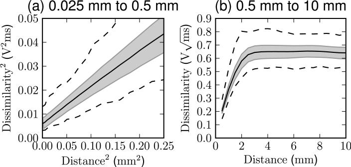
The results of the dissimilarity assessment are plotted in Figure 1. At short distances, below 0.5 mm, the squared dissimilarity is linearly related to the squared distance. At large distances, above 2 mm, the dissimilarity saturates, and becomes constant.
Figure 1.
The dissimilarity measured between all pairs of ultrasound signals separated by a given distance in Experiment A. The center line shows the mean dissimilarity observed at that distance, the shaded region indicates one standard deviation above and below, and the outer lines show the minimum and maximum. Data for nearby points are shown in (a) with quadratically scaled axes, and data for larger distances are shown in (b) with linear scaling.
These behaviors are as expected from a simple model of ultrasound echogenicity, in which the signal changes smoothly on scales smaller than the ultrasound beam width, but becomes uncorrelated at distances larger than the beam width (2.0 mm for this transducer). The offset at zero distance is expected due to factors such as thermal and electrical noise that decrease the similarity of successive measurements even if the location is unchanged.
Importantly, the data suggest that an appropriately chosen dissimilarity threshold may reject all pairs separated by more than 2 mm, and accept all pairs separated by less than 0.5 mm. This is sufficient to enable reliable matching as required by the subsequent experiments.
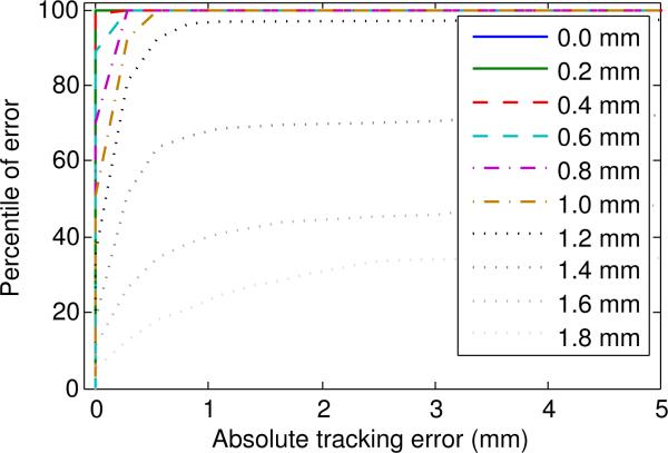
We also acquired data to simulate the effect of a lateral shift on the accuracy of motion tracking. The parameters closely resemble the subsequent experiments, with 256 equally spaced samples in a 70 mm row. We acquired several parallel rows separated by a lateral distance of 0.2 mm. One of these rows was selected as the reference, and the position of each sample was estimated as equal to the position of the most similar echo in the reference row.
The results are shown in Figure 2. The results show that for lateral shifts of up to 1 mm, the simulated tracking error parallel to the reference row was always less than 1 mm. At a lateral shift of 1.2 mm the parallel tracking error was less than 1 mm for 96% of samples, but only 21% of samples were this accurate at a shift of 1.8 mm. These results suggest that, for this phantom, transducer, and geometrical arrangement, lateral shifts of up to 1 mm outside the reference set are unlikely to cause significant tracking errors. This result is consistent with the dissimilarity saturation observed in Figure 1, indicating that the sensitivity to lateral shift is also determined by the shape of the transducer's ultrasound field.
Figure 2.
Cumulative distribution function of tracking error at 10 different lateral shifts. Motion tracking was simulated using a data set acquired using a robotic positioner.
Experiment B: Assessing the accuracy and latency of UL-TRACK
This experiment served to measure the accuracy and latency of ULTRACK's MRI motion compensation by applying the compensation to the navigator itself. If ULTRACK were providing perfectly ideal motion compensation, then the motion-compensated navigator would appear stationary, even though the phantom is moving.
In this experiment, the imaging pulse sequence was Spoiled Gradient-Echo with TE/TR=4.2/8.9 ms, imaging a 22 cm square coronal slice with 10 mm thickness at a resolution of 256 × 256. The frequency encode direction was aligned with the MRI bore. The MRI navigator used for training purposes consisted of the same sequence with phase encoding disabled.
The training period consisted of 104 acquisitions, requiring 89 seconds to complete and covering approximately 9 cycles of the motion phantom. During the training stage, the phantom was set to its larger motion amplitude, akin to asking a patient to breathe deeply during training, in order to ensure that the entire range of motion was observed.
Analyzing the navigator to determine the position of the phantom was trivial because the slice consists of a rigid body moving linearly in air. Once the software had extracted positions from each MRI acquisition, it used this information to select 256 measurements that were evenly spaced in position and spanned the whole observed range of motion.
After training was complete, ULTRACK was configured for motion compensation, and the phantom was changed to its lower motion amplitude. The MRI navigator pulse sequence was run again, this time under prospective compensation from ULTRACK. The positions were extracted again from these data by the same algorithm.
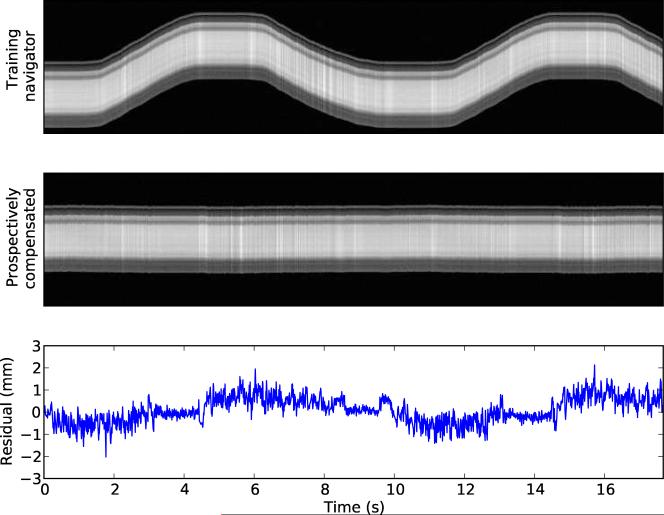
The results of Experiment B are shown in Figure 3. Using prospective motion compensation, ULTRACK reduced the observed standard deviation of position from 25.3 mm to 0.57 mm. This indicates that ULTRACK preserved 97.8% of the MRI navigator's positioning accuracy.
Figure 3.
The top image shows the MRI training data used to compute the mapping table. The middle image shows the result when the same pulse sequence is performed under prospective navigation from this mapping table. The lower plot shows the residual position error in the middle image.
The residual position error in Figure 3 exhibits periodic behavior due to the latency of correction. These data were acquired and reconstructed without predictive filtering, so any delay contributes to the positioning error during prospective compensation. For retrospective motion correction, the delay can easily be removed. By minimizing the observed positioning error, we determined that the total motion compensation delay in this experiment was 27 ms. Retrospectively compensating for this delay reduced the observed standard deviation to 0.35 mm.
Experiment C: Determining the ability of ULTRACK to reduce artifacts in 2D images
This experiment served to determine whether ULTRACK can successfully achieve its goal of reducing motion artifacts in three different types of 2D images: coronal, axial, and oblique. The oblique plane was generated by rotating the coronal slice by approximately 15 degrees from all three cardinal axes (double oblique).
Each image type was tested using the same procedure as in Experiment B, except that phase encoding was enabled during motion compensation. Additionally, a control image set was acquired for each imaging plane with ULTRACK disabled, to determine the effects of motion without compensation.
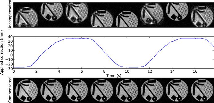
The results indicate that ULTRACK's motion compensation performance is nearly sufficient to eliminate all motion artifacts from the moving object. In the in-plane motion test (Figure 4), the residual artifacts are greatly suppressed, and not easy to see. One source of remaining artifacts is position-dependent geometric distortion due to nonideality of the MRI gradient fields. In static images this distortion is corrected by the gradient warping procedure during reconstruction, but no such correction has been applied here.
Figure 4.
Prospective motion compensation performance for in-plane motion. The top row shows images during uncorrected motion. The bottom row shows images acquired during corrected motion, and the middle row shows the corresponding applied position correction over time. All images are originally 256 × 256, but have been cropped to show the region of interest. The tracking was performed in a homogeneous region of the phantom. Plastic objects were placed behind this region for visualization in MRI.
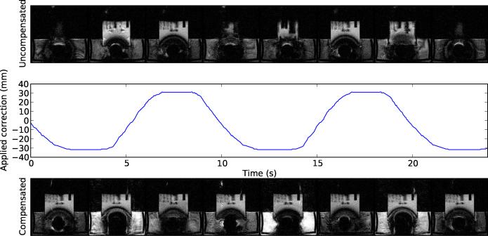
In the through-plane test (Figure 5), the appearance of the moving object is substantially improved compared to the uncorrected images, in which the phantom is often invisible because it has moved out of the imaging plane entirely. Unrelated artifacts are still visible due to turbulence in the water tank and the presence of ferromagnetic material in this ultrasound tranducer.
Figure 5.
Prospective motion compensation performance for through-plane motion, structured as in Figure 4. The dark blooming artifact was caused by ferromagnetic components of the transducer, and the surrounding brightness variation is due to turbulence and saturation effects in the water bath.
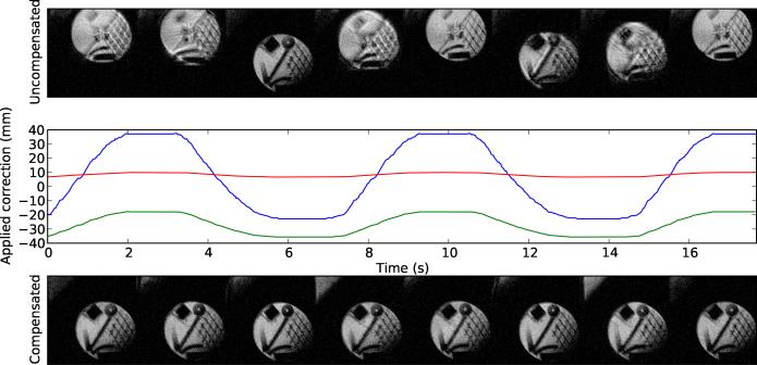
In the oblique test (Figure 6), ULTRACK greatly reduced the appearance of motion artifacts by applying corrections along the phase, read, and slice axes.
Figure 6.
Prospective motion compensation performance for an oblique plane, structured as in Figure 4. In some points along the motion trajectory the oblique imaging plane includes a portion of the water bath, visible in the upper left corner of the compensated images.
Experiment D: Determining whether ULTRACK permits MRI thermometry of a moving phantom
This experiment served to determine whether ULTRACK's motion compensation accuracy is sufficient to enable MRI thermometry of moving objects, using the heating phantom with attached focused ultrasound transducer. The temperature rise was estimated by Proton Resonance Frequency Shift analysis of data from a standard sequence used for this purpose: Spoiled Gradient-Echo (SPGR) with TE/TR=11.7/23.8 ms, and a bandwidth of 3.57 kHz, imaging a 12 cm square coronal slice with a thickness of 3 mm at a resolution of 128 × 128. Compared to Experiment C, motion compensation in this experiment is much more challenging due to this sequence's longer TR and TE, thinner slices, and extreme sensitivity to phase variation.
After waiting for 7 images without heating, 8.3 Watts of electrical power was applied for 60 seconds. This procedure was performed 16 times, while the phantom was alternately stationary or moving with ULTRACK motion compensation. The motion phantom was configured for a period of 18 seconds and a maximum velocity of 1.3 cm/sec.
Temperature changes were computed by referenceless thermometry similar to [23], with a basis consisting of a 5th-order polynomial (the background phase) and a Gaussian spot with variable amplitude and radius (the focal heating). Referenceless thermometry was chosen for its insensitivity to spurious drift and fluctuation [24], to ensure that any systematic temperature error could be detected.
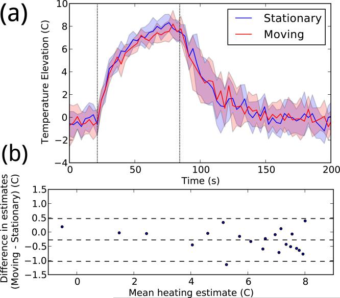
The results indicate that MRI thermometry is possible under ULTRACK guidance. As shown in Figure 7, the temperature curves observed over time are similar. A linear fit between the stationary and moving mean peak temperatures had a slope of 0.92 and a R2 value of 0.96, indicating that any systematic error introduced by motion compensation is small. During heating, the mean standard deviation in peak temperature was 0.83 while stationary and 0.78 while moving, indicating that motion compensation did not introduce significant additional temperature noise.
Figure 7.
(a) Temperature data reconstructed with and without motion. In each color, the central line shows the mean peak temperature timeline for eight experiments, and the shaded area shows one standard deviation above and below. (b) Bland–Altman plot comparing the two sets of temperature measurements. Each point represents a single time during heating (from 21–81 seconds), averaged over all repetitions.
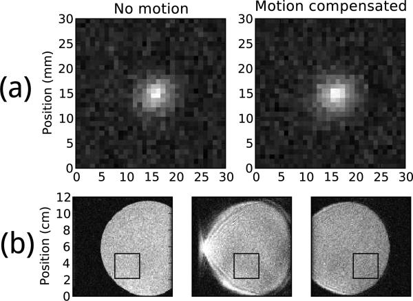
The geometry of the temperature image is also preserved, as seen in Figure 8a, although a slight broadening is evident. Without motion compensation this pulse sequence produces images, shown in Figure 8b, that are corrupted by severe motion artifacts and displacements that would likely preclude any thermometry.
Figure 8.
(a) Average temperature image at 79 seconds (near peak heating) after background phase subtraction. Both images are shown in the same temperature scale. (b) Three consecutive magnitude images of the heating phantom undergoing motion without compensation, using the same pulse sequence as used for temperature images. The black box indicates the image region in which thermometry was performed.
Experiment E: Confirming in vivo feasibility with an animal model
The purpose of this experiment was to confirm whether biometric ultrasound navigation can be accurate and effective in vivo, by analyzing simultaneous ultrasound and MRI data acquired from a freely breathing anesthetized rabbit. For all imaging, the MRI scanner executed a Spoiled Gradient Echo sequence with a resolution of 256×256, 5 mm slice thickness, 31.25 kHz receive bandwidth, and frequency encode along the S/I axis. MRI navigator data were acquired by the same pulse sequence used for imaging, but with phase encoding disabled. The mapping tables contained 256 entries and were computed from a training period lasting 14 seconds.
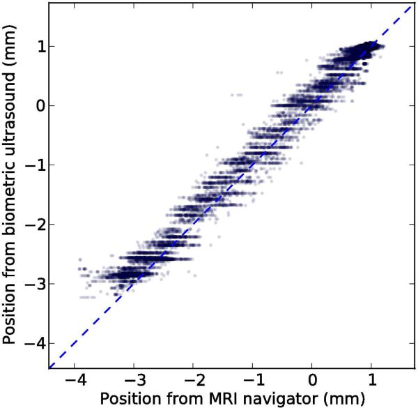
To assess the accuracy of the method in vivo, we acquired 143 seconds of test data consisting of paired navigator and ultrasound acquisitions, similar to the preceding training period. The images represented a coronal slice with a 17 cm square field of view and TE/TR=3.6/7.8 ms. Using the mapping table from the training period, we computed position estimates from the ultrasound data and compared them to the position computed from the navigator, which served as a reference. The paired position measures are plotted in Figure 9.
Figure 9.
Scatter plot showing 17654 paired position measurements acquired in a rabbit during 143 seconds of free breathing. The dashed line represents perfect performance, and the solid line shows the least-squares linear fit.
The standard deviation of the reference position during the test period was 1.41 mm. After subtracting the position estimate from ultrasound, the standard deviation of the residual was 0.16 mm, indicating that the biometric navigator captured 89% of the variation in the MRI navigator. A least-squares linear fit between the two position measures had a slope of 0.95 and a R2 value of 0.98.
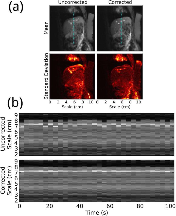
To assess the effectiveness of the method in vivo, we acquired a sagittal image series and training scan with an 11 cm field of view and TE/TR=4.1/11.5 ms. A mapping table was computed from the training scan and used to estimate the displacement at each ultrasound acquisition during the image series. Motion compensation of the MRI images was achieved retrospectively by applying a phase roll to each line of k-space to remove the displacement estimated from ultrasound. This set of MRI data, reconstructed with and without retrospective motion compensation, is visualized in Figure 10, showing a clear improvement in image stability. The correction also greatly reduces the severity of motion artifacts.
Figure 10.
(a) Mean and standard deviation of 32 consecutive images of a freely breathing rabbit, with and without retrospective biometric ultrasound motion compensation. Each image pair is shown in the same contrast. (b) Time series showing a line segment from each image with and without motion compensation, at a location indicated by the dotted lines in (a).
These results show that biometric ultrasound navigation can provide accurate respiratory displacement estimates in vivo, using less than 9% of total imaging time for training. They also demonstrate that the method is effective at producing sharp, stable MRI images during free breathing.
Discussion
Biometric navigation is distinguished from other position measurement methods by its use of a unique identifier derived from the tissue at each location. This identifier does not itself indicate a position, but its biometric uniqueness ensures that once a position is associated with an identifier, the position will not be indicated spuriously. The uniqueness of the identifier representing each location is due to the large entropy of the high-dimensional space from which biometric patterns are randomly drawn.
In the case of ultrasound navigators, entropy is provided by reflections from macroscopic anatomical structures, but also by sound scattered off of countless microstructures. The resulting interference pattern is termed speckle, and is well approximated by a broadband Gaussian random field that does not change with time unless the relevant microstructures are moved or altered [25].
We may estimate the entropy of ultrasound navigators by considering only the speckle and applying the Shannon-Hartley channel capacity theorem for a noisy channel [26]:
| (3) |
In our experiments a typical ultrasound transducer has bandwidth of at least B = 1.5 MHz and signal-to-noise ratio of at least S/N = 3. (Note that although speckle is often regarded as noise, here the time-invariant speckle is signal.) From these parameters we compute a channel capacity of C = 3 Megabits per second, or 4 bits/mm in pulse-echo ultrasound. (For comparison, biometric iris scans exhibit an effective entropy of 3.2 bits/mm2 [27].) A target region 20 mm in size would have an entropy of 80 bits, or a collision probability of 10−24. This strong expectation of uniqueness motivates our study of ultrasound navigators for position tracking.
A related approach [15] has recently been presented, using the signal produced by a respiratory bellows to identify the current liver position. These methods are both indirect: they require a training period to determine the correspondence between the measured quantity and the actual anatomical position. Both methods are therefore constrained by the contents of the training data; they cannot track motion with more accuracy than the navigator used to train them, and they can only estimate positions along axes measured by the navigator. They are distinguished, however, by the dimensionality of the measured quantity. A bellows measures a single one-dimensional value, which therefore is not biometrically unique. Without biometric uniqueness, the system cannot detect when the training data are no longer applicable, which may occur if the patient moves laterally or the organs undergo any unanticipated shift. One-dimensional measurements are also restricted to reciprocal motion models unless strong assumptions are made about the true motion cycle (as in cardiac MRI with ECG gating).
In this method, the unique identifier takes the form of an ultrasound echo transverse to the axis of motion, windowed in depth so that the data correspond to a specific volume of interest. The distinct identifiability of echoes at each position may be provided by macroscopic anatomical structures, or by microscopic tissue structures whose scattering fields interfere to form speckle. The phantoms used in this study have no macroscopic ultrasound structure, only speckle.
The ultrasound properties of human tissues are complex, and neither phantom nor animal experiments mimic them rigorously. When used in humans, ULTRACK may require a more sophisticated dissimilarity function. A suitable function might be derived from the displacement tracking techniques developed for ultrasound elastography and Doppler imaging [28].
This method relies especially on the assumption that the ultrasound properties of a volume of tissue are highly repeatable over the course of an imaging session. To the extent that this assumption holds true, biometric navigation can function during arbitrary repetitive motions, even if the pattern includes nonrigid deformations that alter the speckle pattern (although only the motion components visible in the MRI training data can be reported). However, if the ultrasound appearance of the tissue is not stable over many breath cycles, the method may require such frequent re-training that it cannot offer a significant benefit.
The animal experiments show stable tracking performance over a period 10 times longer than the training period, indicating that the repeatability of ultrasound appearance and breathing patterns may be sufficiently high for this technique to function as desired in vivo. However, human breathing patterns, and the motions they produce, are complex [29]. They may vary from cycle to cycle, or drift over longer timescales, to a greater degree than was observed in our animal experiment. Stimuli experienced during an intervention such as focused ultrasound surgery might cause patients to alter their breathing patterns.
Motions outside of the training data, due to a gross patient shift or other unexpected motion, would result in ultrasound echoes that do not imply any position because they do not resemble any entry in the mapping table, effectively rendering the training invalid. Extensions to ULTRACK, such as occasional retraining when drift is detected, may help to improve performance in real use, but such extensions have not yet been tested.
High sensitivity to lateral or unexpected motions is not appropriate for all imaging applications, but it is a valuable safety feature in focused ultrasound surgery, where it is crucial to detect any unexpected displacement instantly. The transducers used in this study were designed for high sensitivity to lateral shifts, consistent with their focal width of 2 mm. For applications in which lower sensitivity is desirable, we may be able to broaden the focus by changing the transducer's geometry.
The motion of the human liver during breathing is not exactly a linear shift, so motion compensation in the liver may benefit from a position model with more degrees of freedom [30]. There are several possible ways to extend ULTRACK to prospective correction of nonlinear motions, including the use of multi-dimensional navigators, but they have not yet been demonstrated.
Conclusions
Ultrasound biometric navigation appears to be a promising technique for motion compensation of dynamic MRI. Using relatively inexpensive hardware and simple software, we have implemented the technique and demonstrated that it achieves excellent artifact reduction in mechanical and animal models of human respiratory motion. The accuracy is sufficient to enable temperature monitoring in a moving object, modeling the requirements of MRI-guided focused ultrasound surgery during free breathing. The speed and reliability of the technique may also be sufficient to serve as a safety-critical position monitor during image-guided interventions. However, more experiments are needed in order to determine whether the technique will work as desired in human patients.
Supplementary Material
Acknowledgements
This work was supported by NIH grants P01CA067165, P41RR019703, and P41EB015898. RTHawk was provided by Dr. Juan Santos and HeartVista; OpenIGTlink was provided by Dr. Junichi Tokuda. The authors are grateful to Dr. Scott Hoge for his help installing, maintaining, and explaining these systems. The pairwise dissimilarities in Experiment A were computed on the Orchestra cluster supported by the Harvard Medical School Research Information Technology Group. We are especially thankful to Dr. Yong-Zhi Zhang and Dr. Eun-Joo Park for making the animal imaging experiments possible.
Appendix: Optimized Computation of Discretized Dissimilarity
Biometric navigation, when used in real-time applications such as prospective motion compensation, requires fast computation of dissimilarity between newly measured biometric data and entries in the mapping table. For biometric ultrasound, this means a fast method of computing the dissimilarity function described by Equation 2. To find a fast implementation, we first reformulate Equation 2 to expand the quadratic and extract constant terms:
| (4) |
| (5) |
| (6) |
To achieve maximum speed, we choose a simple rectangular window function
| (7) |
and define new windowed ultrasound vectors
| (8) |
| (9) |
This simplifies our formula to
| (10) |
For convenience we define
| (11) |
| (12) |
| (13) |
so that
| (14) |
If computed naively, R will require an independent sum over products at each value of s, requiring Θ(N2) computation time. To perform the computation faster, we first note that R is the cross-correlation vector of x and y:
| (15) |
By the Fourier cross-correlation theorem, Equation 15 is equivalent to
| (16) |
where represents a discrete Fourier transform of length at least 2N − 1. With a Fast Fourier Transform, this allows d2 to be computed in (NlogN) time.
In our implementation, the dissimilarity function is used to compare a newly acquired ultrasound signal v with each vector U from the mapping table. Because all the vectors U are known before real-time computation starts, we may compute and store P and ahead of time. We also only compute Q and once for each new signal, and reuse these values in each of the dissimilarity computations. If there are K entries in the mapping table, then these choices reduce the total number of P and Q computations required for each search from 2K to 2, and the total number of forward and inverse transforms from 3K to K + 1. We use the FFTW package [31] to compute these transforms quickly, and perform the other computations in C++.
Because each of the K computations of d2 is independent, they may be performed in parallel. We use the OpenMP multithreading abstraction to spread these K computations across CPU cores. As expected, we observe near-perfect linear scaling with the number of cores. On an 8-core 2.5 GHz Xeon E3560, with N = 4096 and K = 256, we observed an average table search time of 2.5 ms, i.e. 400 Hz, or 100,000 computations of d2 per second. This is significantly faster than required by our current experiments, indicating that larger mapping tables may be feasible. Some possibilities for future optimization, should it be necessary, include the use of extremely parallel hardware such as GPUs, and excluding unlikely (i.e. distant) reference vectors from consideration.
Contributor Information
Benjamin M. Schwartz, Harvard Biophysics
Dr Nathan J. McDannold, Brigham and Women's Hospital Harvard Medical School.
References
- 1.Wang Y, Rossman PJ, Grimm RC, Riederer SJ, Ehman RL. Navigator-echo-based real-time respiratory gating and triggering for reduction of respiration effects in three-dimensional coronary MR angiography. Radiology. 1996 Jan;198:55–60. doi: 10.1148/radiology.198.1.8539406. [DOI] [PubMed] [Google Scholar]
- 2.Ross JC, Tranquebar R, Shanbhag D. Real-Time liver motion compensation for MRgFUS. In: Metaxas D, Axel L, Fichtinger G, Szkely G, editors. Medical Image Computing and Computer-Assisted Intervention MICCAI 2008. Vol. 5242. Springer Berlin Heidelberg; Berlin, Heidelberg: 2008. pp. 806–813. [DOI] [PubMed] [Google Scholar]
- 3.Ehman RL, Felmlee JP. Adaptive technique for high-definition MR imaging of moving structures. Radiology. 1989 Oct;173:255–263. doi: 10.1148/radiology.173.1.2781017. [DOI] [PubMed] [Google Scholar]
- 4.McConnell MV, Khasgiwala VC, Savord BJ, Chen MH, Chuang ML, Manning WJ, Edelman RR. Prospective adaptive navigator correction for breath-hold MR coronary angiography. Magnetic Resonance in Medicine. 1997 Jan;37:148–152. doi: 10.1002/mrm.1910370121. [DOI] [PubMed] [Google Scholar]
- 5.Scott AD, Keegan J, Firmin DN. Motion in cardiovascular MR imaging1. Radiology. 2009 Feb;250:331–351. doi: 10.1148/radiol.2502071998. [DOI] [PubMed] [Google Scholar]
- 6.Ries M, de Senneville BD, Roujol S, Berber Y, Quesson B, Moonen C. Real-time 3D target tracking in MRI guided focused ultrasound ablations in moving tissues. Magnetic Resonance in Medicine. 2010 Sep;:1704–1712. doi: 10.1002/mrm.22548. [DOI] [PubMed] [Google Scholar]
- 7.Shakespeare SA, Moore RJ, Crowe JA, Gowland PA, Hayes-Gill BR. A method for foetal heart rate monitoring during magnetic resonance imaging using doppler ultrasound. Physiological Measurement. 1999 Nov;20:363–368. doi: 10.1088/0967-3334/20/4/303. [DOI] [PubMed] [Google Scholar]
- 8.Günther M, Feinberg DA. Ultrasound-guided MRI: preliminary results using a motion phantom. Magnetic Resonance in Medicine. 2004;52(1):27–32. doi: 10.1002/mrm.20140. [DOI] [PubMed] [Google Scholar]
- 9.Curiel L, Chopra R, Hynynen K. Progress in multimodality imaging: Truly simultaneous ultrasound and magnetic resonance imaging. IEEE transactions on medical imaging. 2007 Dec;26:1740–1746. doi: 10.1109/tmi.2007.903572. PMID: 18092742 PMCID: 2862902. [DOI] [PMC free article] [PubMed] [Google Scholar]
- 10.Tang AM, Kacher DF, Lam EY, Wong KK, Jolesz FA, Yang ES. Simultaneous ultrasound and MRI system for breast biopsy: Compatibility assessment and demonstration in a dual modality phantom. IEEE Transactions on Medical Imaging. 2008 Feb;27:247–254. doi: 10.1109/TMI.2007.911000. [DOI] [PubMed] [Google Scholar]
- 11.de Oliveira PL, de Senneville BD, Dragonu I, Moonen CTW. Rapid motion correction in MR-guided high-intensity focused ultrasound heating using real-time ultrasound echo information. NMR in Biomedicine. 2010 Nov;23:1103–1108. doi: 10.1002/nbm.1526. [DOI] [PubMed] [Google Scholar]
- 12.Pernot M, Tanter M, Fink M. 3-D real-time motion correction in high-intensity focused ultrasound therapy. Ultrasound in Medicine & Biology. 2004 Sep;30:1239–1249. doi: 10.1016/j.ultrasmedbio.2004.07.021. [DOI] [PubMed] [Google Scholar]
- 13.Feinberg DA, Giese D, Bongers DA, Ramanna S, Zaitsev M, Markl M, Günther M. Hybrid ultrasound MRI for improved cardiac imaging and realtime respiration control. Magnetic Resonance in Medicine. 2010 Feb;63:290–296. doi: 10.1002/mrm.22250. [DOI] [PMC free article] [PubMed] [Google Scholar]
- 14.Bell MAL, Byram BC, Harris EJ, Evans PM, Bamber JC. In vivo liver tracking with a high volume rate 4D ultrasound scanner and a 2D matrix array probe. Physics in Medicine and Biology. 2012 Mar;57:1359–1374. doi: 10.1088/0031-9155/57/5/1359. [DOI] [PubMed] [Google Scholar]
- 15.Pauly KB, Holbrook A, Santos J, Ghanouni P. Program & Abstract Book. Focused Ultrasound Surgery Foundation; Washington, D.C., USA: 2010. Focused ultrasound of the liver during free breathing; p. 95. [Google Scholar]
- 16.Holbrook AB, Dumoulin CL, Santos JM, Medan Y, Pauly KB. Proceedings of the International Society for Magnetic Resonance in Medicine. Vol. 19. International Society for Magnetic Resonance in Medicine; Montreal - Quebec, Canada: May, 2011. Real time respiration based steering for high intensity focused ultrasound in the liver; p. 525. [Google Scholar]
- 17.McDannold N. Quantitative MRI-based temperature mapping based on the proton resonant frequency shift: review of validation studies. International Journal of Hyperthermia: The Official Journal of European Society for Hyperthermic Oncology, North American Hyperthermia Group. 2005 Sep;21:533–546. doi: 10.1080/02656730500096073. PMID: 16147438. [DOI] [PubMed] [Google Scholar]
- 18.Partanen A, Mougenot C, Vaara T. Feasibility of Agar-Silica phantoms in quality assurance of MRgHIFU. AIP Conference Proceedings. 2009 Apr;1113:296–300. [Google Scholar]
- 19.Davies SC, Hill AL, Holmes RB, Halliwell M, Jackson PC. Ultrasound quantitation of respiratory organ motion in the upper abdomen. Br J Radiol. 1994 Nov;67:1096–1102. doi: 10.1259/0007-1285-67-803-1096. [DOI] [PubMed] [Google Scholar]
- 20.Santos J, Wright G, Pauly J. Flexible real-time magnetic resonance imaging framework. Engineering in Medicine and Biology Society, 2004. IEMBS ’04. 26th Annual International Conference of the IEEE. 2004;1:1048–1051. doi: 10.1109/IEMBS.2004.1403343. [DOI] [PubMed] [Google Scholar]
- 21.Tokuda J, Fischer GS, Papademetris X, Yaniv Z, Ibanez L, Cheng P, Liu H, Blevins J, Arata J, Golby AJ, Kapur T, Pieper S, Burdette EC, Fichtinger G, Tempany CM, Hata N. OpenIGTLink: an open network protocol for image-guided therapy environment. The international journal of medical robotics + computer assisted surgery : MRCAS. 2009 Dec;5:423–434. doi: 10.1002/rcs.274. PMID: 19621334 PMCID: 2811069. [DOI] [PMC free article] [PubMed] [Google Scholar]
- 22.Ishihara Y, Calderon A, Watanabe H, Okamoto K, Suzuki Y, Kuroda K, Suzuki Y. A precise and fast temperature mapping using water proton chemical shift. Magnetic Resonance in Medicine. 1995 Dec;34:814–823. doi: 10.1002/mrm.1910340606. [DOI] [PubMed] [Google Scholar]
- 23.Rieke V, Vigen KK, Sommer G, Daniel BL, Pauly JM, Butts K. Referenceless PRF shift thermometry,” Magnetic Resonance in Medicine. 2004 Jun;51:1223–1231. doi: 10.1002/mrm.20090. [DOI] [PubMed] [Google Scholar]
- 24.de Senneville BD, Roujol S, Moonen C, Ries M. Motion correction in MR thermometry of abdominal organs: A comparison of the referenceless vs. the multibaseline approach. Magnetic Resonance in Medicine. 2010 Nov;64:1373–1381. doi: 10.1002/mrm.22514. [DOI] [PubMed] [Google Scholar]
- 25.Abbott JG, Thurstone F. Acoustic speckle: Theory and experimental analysis. Ultrasonic Imaging. 1979 Oct;1:303–324. doi: 10.1177/016173467900100402. [DOI] [PubMed] [Google Scholar]
- 26.Shannon CE. Communication in the presence of noise. Proceedings of the IRE. 1949 Jan;37:10–21. [Google Scholar]
- 27.Daugman J. The importance of being random: statistical principles of iris recognition. Pattern Recognition. 2003 Feb;36:279–291. [Google Scholar]
- 28.Viola F, Walker WF. A comparison of the performance of time-delay estimators in medical ultrasound. IEEE Transactions on Ultrasonics, Ferroelectrics and Frequency Control. 2003 Apr;50:392–401. doi: 10.1109/tuffc.2003.1197962. [DOI] [PubMed] [Google Scholar]
- 29.Blackall JM, Ahmad S, Miquel ME, McClelland JR, Landau DB, Hawkes DJ. MRI-based measurements of respiratory motion variability and assessment of imaging strategies for radiotherapy planning. Physics in Medicine and Biology. 2006 Sep;51:4147–4169. doi: 10.1088/0031-9155/51/17/003. [DOI] [PubMed] [Google Scholar]
- 30.Rohlfing T, Maurer CR, ODell WG, Zhong J. Modeling liver motion and deformation during the respiratory cycle using intensity-based nonrigid registration of gated MR images. Medical Physics. 2004;31:427. doi: 10.1118/1.1644513. [DOI] [PubMed] [Google Scholar]
- 31.Frigo M, Johnson S. The design and implementation of FFTW3. Proceedings of the IEEE. 2005;93(2):216–231. [Google Scholar]
Associated Data
This section collects any data citations, data availability statements, or supplementary materials included in this article.


