Abstract
Controlled three-dimensional (3D) rotation of arbitrarily shaped objects in the observation space of optical microscopes is essential for realizing tomographic microscope imaging and offers great flexibility as a noncontact micromanipulation tool for biomedical applications. Herein, we present 3D rotational control of inhomogeneous biological samples using 3D optical multiple-force clamps based on time-shared scanning with a fast focus-tunable lens. For inhomogeneous samples with shape and optical anisotropy, we choose diatoms and their fragments, and demonstrate interactive and controlled 3D rotation about arbitrary axes in 3D Cartesian coordinates. We also outline the hardware setup and 3D rotation method for our demonstrations.
OCIS codes: (350.4855) Optical tweezers or optical manipulation, (140.7010) Laser trapping, (170.4520) Optical confinement and manipulation, (170.0170) Medical optics and biotechnology
1. Introduction
Precise optical controlled manipulation of non-spherical micro-objects, especially synthetic microstructures [1] and biological samples such as diatoms [2, 3], is of widespread importance but is a challenging task. Such manipulations must occur in a three-dimensional (3D) microscopic working space, where their motion generally has six degrees-of-freedom (6DOF), that is, 3D translation and 3D rotation. In particular, since the 3D rotation of single cells can provide two-dimensional (2D) views of their subcellular structures from different directions [4–7], the precise control techniques of 3D rotation can be used for the realization of computer tomographic (CT) microscope imaging [8].
However, until now, the precise rotation of microscopic samples for 3D tomographic imaging has required an intricate setup of electric motors [9, 10], because non-mechanical methods using optical forces have not yet established owing to several limitations. First, in the case of using single-beam scanning optical tweezers [5, 6], the control parameters (for example, scanning pattern, and laser power) with regard to the tilt angles (namely, rotation angles around an arbitrary axis perpendicular to the optical axis of an objective lens) strongly depend on the shape and optical properties of samples. This is because their stable posture is a result of a delicate balance between the optical force acting on the broad area by scanning and other forces such as gravity and buoyancy [6]. Therefore, aside from simple shapes such as rod-shaped bacterium [5], it may be impossible to precisely control complicated samples without an intelligent visual-feedback approach. Secondly, although counter-propagating divergent beam traps with either optical fibers [4] or the GPC method [11] could well perform the 3D rotation of inhomogeneous samples under objective lenses with low magnifications, custom-made devices for generating counter-propagating beams and the precise alignment of their opposing beams are essential for these methods. The visual-feedback approach is also required [12], because their axial performances are governed by the wave propagation of opposing beams. Thirdly, in the case of using holographic optical tweezers, the precise 3D rotation of non-spherical micro-objects has not yet been demonstrated to the best of our knowledge, apart from known-shaped sphere-connected structures [13]. This is because the real-time generation of multiple traps with uniform trapping forces at each specified 3D coordinate has not been established, and is a challenging task.
In this paper, we present the 3D rotational control of inhomogeneous biological samples using 3D optical multiple-force clamps based on time-shared scanning with a fast focus-tunable lens. For inhomogeneous samples with shape and optical anisotropy, we choose diatoms and their fragments, and demonstrate interactive and controlled 3D rotation about arbitrary axes in 3D Cartesian coordinates. We also outline the hardware setup and the 3D rotation method for our demonstrations.
2. Optical multiple-force clamps with 3D-T3S optical tweezers
Optical multiple-force clamps are based on multiple-beam optical tweezers, in which some beams irradiate different parts of a single object, maintaining the relative positions of the traps. Time-shared synchronized scanning (T3S) is a suitable method for real-time independent control of multiple traps, as it is simple to generate and change trapping positions, saving computation time in complicated control algorithms based on intelligent control techniques [14]. In addition, for enhancing precision-based biomedical applications such as tomographic cell imaging and cell stretching [15], T3S optical tweezers based on single-beam gradient-force optical traps using a single objective lens are a practical and low-cost technique, because they can use a commercially available standard microscope and do not require a spatial light modulator (SLM). Furthermore, the T3S method operates not under diffractive optics but under geometrical optics, and therefore the positions of generated traps experience no obscurity, such as the ghost traps emerging in the dynamic hologram using SLMs. Recently, based on the above-mentioned superior features of the T3S approach, we have presented a 3D multiple optical tweezers system with a fast focus-tunable lens [16]. Thus, in this work, we choose the same 3D-T3S optical tweezers technique for the physical method of applying a 3D optical multiple-force clamps technique.
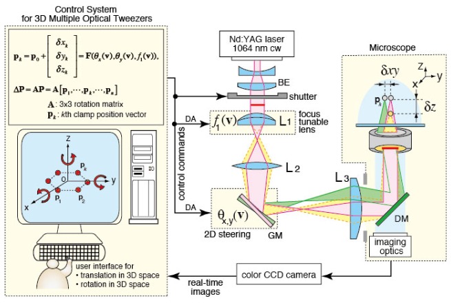
Figure 1 illustrates the optical and control system configuration of the 3D-T3S optical tweezers for the multiple-force clamps, where L1, L2, L3, and GM denote the electrically focus-tunable lens (Optotune, EL-10-30-NIR-LD), the relay lenses, and the electrically controlled 2-axis gimbal-mirror (Newport, FSM-300), respectively. The 3D position of the kth trap, pk = [xk, yk, zk]T (where superscript T denotes the transpose of a matrix), generated by the time-shared scanning can be directly specified by a function of the GM’s tilt angles in the x and y directions and the L1’s focal length, pk = F(θx, θy, f1). Hence, each pk is continuously and independently controlled in 3D Cartesian coordinates by digital–analog (DA) voltages v corresponding to the GM’s tilt angles, θx(v) and θy(v), and the L1’s focal length, f1(v). Using a 3 × 3 rotation matrix A, the 3D rotation, ΔP, of the traps, which comprise the multiple-force clamps in 3D Cartesian coordinates, can be expressed as ΔP = A[p1,…,pn]. Consequently, the 3D rotation of the multiple-force clamps can be also controlled directly by the DA voltages. Further details of the optical design and the control methods for the 3D multiple traps can be found in our previous paper [16].
Fig. 1.
Optical and control system configurations for controlled rotation of biological cells based on the optical multiple-force clamps technique.
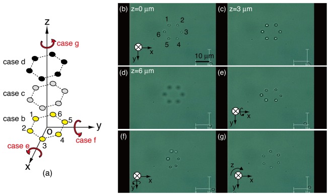
To verify the performance of the 3D optical multiple-force clamps using our 3D-T3S optical tweezers system, we made a preliminary demonstration of the 3D-controlled movements of multiple traps, where a single microbead (Duke Scientific, borosilicate, 2.5 μm) was trapped at each trap position, maintaining their relative distances to each other. Figure 2 (Media 1 (3.3MB, MOV) ) shows the snapshots captured with a CCD camera and presents the results of the controlled movements of six beads that are dynamically trapped to form a hexagon in 3D Cartesian coordinates. The positions of the six beads are indicated in Fig. 2(a) by the numbers corresponding to the hexagon’s corners. First, these were trapped at their initial positions (that is, the hexagon’s corners) on an xy-plane (Fig. 2(b)). Second, the six beads forming the hexagon were translated along the z-axis to other xy-planes with different z-coordinates (Figs. 2(c) and 2(d)). Third, the six beads were returned to the initial xy-plane and subsequently rotated about the x-axis (Fig. 2(e)), y-axis (Fig. 2(f)), and z-axis (Fig. 2(g)) in 3D Cartesian coordinates. As shown in Figs. 2(e) and 2(f), the multiple trap positions, which were generated on an initial xy-plane, can be simply rotated about the x- and y-axes as well as about the z-axis while maintaining their 3D relative distances to each other. Thus, in the next section, we demonstrate interactive and controlled 3D rotation of non-spherical samples using this technique.
Fig. 2.

(Media 1 (3.3MB, MOV) ) (a) Controlled movements of six micro-beads forming a hexagon. (b–d) Translation along the z-axis. Rotation about the (e) x-axis, (f) y-axis, and (g) z-axis. The accompanying movie is in real-time, not accelerated.
3. Demonstrations
3.1 Samples
Diatoms, which have silica cell walls consisting of two interlocking valves, are non-spherical, unicellular microscopic algae. The study of diatoms is important for fields such as ecology, palaeoecology, and forensic science [17]; some diatoms are also useful for force probing of micro objects [3]. Many diatoms nearly always offer a repeatable 2D view in images provided by a conventional microscopic observation, because their valves are sufficiently flat that they can lie stably on the microscope slide. Accordingly, we chose diatoms and their fragments as non-spherical samples for our demonstrations. The diatoms were collected from a creek in the Kagawa prefecture of Japan and cleaned in an acid solution to remove organic matter in the samples. We selected diatoms and their fragments ranging in size from 20 to 30 μm long from the viewpoint of acting clamp forces and the visual observation area of their 3D orientation by a color CCD camera with a × 100 objective lens.
3.2 Controlled 3D rotations of diatoms
Here we demonstrate the interactive and controlled 3D rotations of diatoms and their fragments in water using the optical two-, three-, and four-point clamp techniques. The laser power at the entrance pupil of the objective lens (Olympus, UPlanSApo × 100, 1.40 NA, IR) was 300 mW, and the dwell time for scanning each clamp position was 15 ms. In the demonstrations, all the initial clamp points were located on an xy-plane, and subsequent 3D rotations of the clamped samples about arbitrary axes were performed using the 3 × 3 rotation matrices:
| (1) |
| (2) |
and:
| (3) |
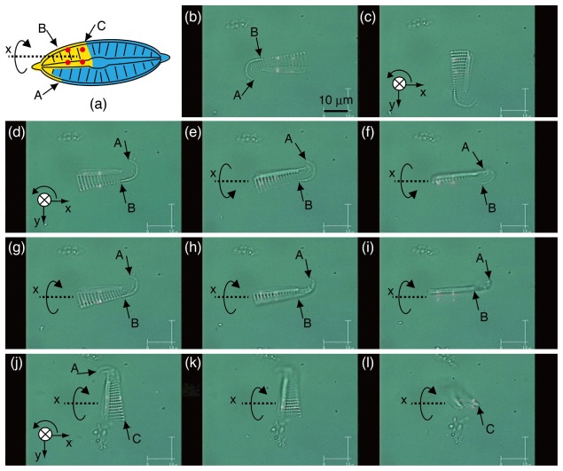
Figure 3 (Media 2 (4.1MB, MOV) ) shows snapshots of the interactive and controlled 3D rotation of the fragment of a single diatom using the optical four-point clamps. In Fig. 3(a), the clamped fragment is colored yellow in the restoration of the diatom, and the points indicated by letters A, B, and C correspond to the points indicated by the same letters in Figs. 3(b)–3(l). The square-clamp points (that is, four-point clamps) illustrated by the red circles in Fig. 3(a) can be identified by the red light spots in Figs. 3(b)–3(l), which appear when the coaxial He-Ne laser beams are introduced for visualizing the clamp positions. First, the fragment was clamped stably by four trap points and subsequently rotated to the desired angle θz about the z-axis interactively, by applying the rotation matrix of Eq. (3) (Figs. 3(b)–3(d)). Second, by applying the rotation matrix of Eq. (1), the fragment could be rotated by angle θx about the x-axis within an approximate range varying from −60° to 60° degrees (Figs. 3(e)–3(h)). However, this fragment turned 90° autonomously if the commanded angle was θx > 60° or θx < −60°, which was due to the undesired release of two of the four clamps (Fig. 3(i)). Third, Figs. 3(j)–3(l) show a video frame sequence of another controlled 3D rotation of the same fragment; the fragment was rotated about its shorter axis, which was parallel to the x-axis in the 3D Cartesian coordinates. The 2D views of these postures cannot be observed without controlled rotation using three-point clamps at least. Thus, we were able to control the fragment in the 3D working space to obtain 2D views of different postures.
Fig. 3.
Interactive and controlled 3D rotation of the fragment of a diatom. (a) Illustration of the fragment (colored yellow) and optical square-clamp points (shown as red circles). (b–l) (Media 2 (4.1MB, MOV) ) Video frame sequence of the controlled rotations of the fragment in the 3D working space. The accompanying movie is in real-time, not accelerated.
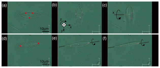
In another two demonstrations, shown in Fig. 4, a complete diatom body was rotated in a 3D working space using two different optical multiple-force clamps. In the case of using three-point clamps (Figs. 4(a)–4(c), Media 3 (2.3MB, MOV) ), a diatom was clamped stably at its valve edges using the triangle-clamp points, which are indicated by the red circles in Fig. 4(a), on an xy-plane. After a controlled rotation of θz = 90° about the z-axis (Fig. 4(b)), the diatom was controlled interactively to rotate about the x-axis (Fig. 4(c)). Consequently, the diatom’s longer axis gradually became parallel to the z-axis in 3D Cartesian coordinates. On the other hand, in the case of using two-point clamps (Figs. 4(d)–4(f), Media 4 (721.7KB, MOV) ), a similar-shaped diatom was clamped at its raphe sternum (that is, the central area of the diatom) using two trap points. Unlike the three-point clamps method, which can rigidly clamp a non-spherical object, the two-point clamps method cannot clamp it rigidly, because the non-spherical object in a 3D working space has 3DOF of rotation, and a non-controllable 1DOF remains in the clamped object. The axial extent of a two-point clamp is considerably longer than the lateral extent, and diatoms prefer to align themselves along the z-axis if possible [2, 6]. Therefore, the diatom trapped at its raphe sternum using the two-point clamps autonomously turned 90° about its longer axis (Figs. 4(e)–4(f)).
Fig. 4.

Video frame sequences of 3D rotations of diatoms using two different optical multiple-force clamps (shown as red circles). (a–c) (Media 3 (2.3MB, MOV) ) Controlled rotation of the diatom using the optical triangle-clamp points. (d–f) (Media 4 (721.7KB, MOV) ) Autonomous rotation of the diatom using the optical two-point clamps. The accompanying movies are in real-time, not accelerated.
3.3 Discussion
For 6DOF control (that is, 3D translation and 3D rotation) of a rigid body without symmetry, a necessary and sufficient condition is a triangle-clamp on the body and 3D control of the clamp positions while maintaining their relative distances. Our 3D-T3S tweezers system, based on geometrical optics, can simply perform the 6DOF control under this condition, because each clamp position in 3D Cartesian coordinates can be strictly specified by the DA voltages that have a one-to-one correspondence with the 3D Cartesian coordinates. Therefore, the four-point clamps (or clamps of more than four points) on the diatom fragment, as shown in Fig. 3, are redundant for the 6DOF control of a non-spherical object. However, the 6DOF-controlled manipulation can be performed better using the redundant clamps (that is, the square-clamp points) than by using the triangle-clamp points, because the accidental release of some traps or the unavoidable obscuring of clamped positions behind the rotating object often occurs in practical demonstrations.
In many applications that require the 3D rotation of cells, the selection of clamp positions is important both for stable clamps and for no undesired-release of clamps. The margin of the relative distance between clamps is also important for 3D rotation using the 3D-T3S method. This is because the z-axial positions of a clamped object change with rotation around an arbitrary axis perpendicular to z-axis, resulting the settlement of its clamp positions with different z-coordinates has delay owing to the response time of a focus-tunable lens. In our demonstration for diatoms, the most effective clamp positions were their edge (namely, the inner boundary between a cell and ambient water), which can be automatically chosen for the given diatoms using image processing techniques when necessary [2].
For the realization of single-cell CT imaging, the current accuracy of the 3D rotations demonstrated here may be insufficient, owing to the delayed response and distortion of the electrically focus-tunable lens [18]. However, the accuracy will be improved if the system is installed with a vision-feedback scheme based on the measurement [12] or estimation [19] of the z-axial positions of a clamped object, as well as the precise calibration in z-axis coordinates.
4. Conclusion
We have demonstrated the feasibility of controlled 3D rotation of inhomogeneous biological samples based on an optical multiple-force clamps technique using our 3D-T3S optical tweezers system. This approach easily enabled us to observe the different 2D views of the 3D structure of diatoms and their fragments with natural shapes and optical properties, via interactive and controlled rotation about arbitrary axes in 3D Cartesian coordinates. Although the demonstrations performed here were only controlled 3D rotations, the multiple-force clamps, especially the four-point clamps, based on the 3D-T3S technique can simply provide 6DOF control of a micro-object. This technique can be introduced to applications such as the probing of 3D microstructures [11, 20], under a commercially available standard microscope. Furthermore, the technique of optical multiple-force clamps can also be expanded to exciting application tools such as 3D noncontact mechanotransduction for live cells [21].
Acknowledgment
This work was partly supported by JSPS KAKENHI Grant No. 24560318.
References and links
- 1.Palima D., Glückstad J., “Gearing up for optical microrobotics: micromanipulation and actuation of synthetic microstructures by optical forces,” Laser Photonics Rev. 7(4), 478–494 (2013). 10.1002/lpor.201200030 [DOI] [Google Scholar]
- 2.Tanaka Y., Kawada H., Hirano K., Ishikawa M., Kitajima H., “Automated manipulation of non-spherical micro-objects using optical tweezers combined with image processing techniques,” Opt. Express 16(19), 15115–15122 (2008). 10.1364/OE.16.015115 [DOI] [PubMed] [Google Scholar]
- 3.Phillips D. B., Simpson S. H., Grieve J. A., Gibson G. M., Bowman R., Padgett M. J., Miles M. J., Carberry D. M., “Position clamping of optically trapped microscopic non-spherical probes,” Opt. Express 19(21), 20622–20627 (2011). 10.1364/OE.19.020622 [DOI] [PubMed] [Google Scholar]
- 4.Kreysing M. K., Kiessling T., Fritsch A., Dietrich C., Guck J. R., Käs J. A., “The optical cell rotator,” Opt. Express 16(21), 16984–16992 (2008). 10.1364/OE.16.016984 [DOI] [PubMed] [Google Scholar]
- 5.Carmon G., Feingold M., “Rotation of single bacterial cells relative to the optical axis using optical tweezers,” Opt. Lett. 36(1), 40–42 (2011). 10.1364/OL.36.000040 [DOI] [PubMed] [Google Scholar]
- 6.Tanaka Y., Hirano K., Nagata H., Ishikawa M., “Real-time three-dimensional orientation control of non-spherical micro-objects using laser trapping,” Electron. Lett. 43(7), 412–414 (2007). 10.1049/el:20073687 [DOI] [Google Scholar]
- 7.Hörner F., Woerdemann M., Müller S., Maier B., Denz C., “Full 3D translational and rotational optical control of multiple rod-shaped bacteria,” J. Biophotonics 3(7), 468–475 (2010). 10.1002/jbio.201000033 [DOI] [PubMed] [Google Scholar]
- 8.Swoger J., Verveer P., Greger K., Huisken J., Stelzer E. H. K., “Multi-view image fusion improves resolution in three-dimensional microscopy,” Opt. Express 15(13), 8029–8042 (2007). 10.1364/OE.15.008029 [DOI] [PubMed] [Google Scholar]
- 9.Shaw P. J., Agard D. A., Hiraoka Y., Sedat J. W., “Tilted view reconstruction in optical microscopy. Three-dimensional reconstruction of Drosophila melanogaster embryo nuclei,” Biophys. J. 55(1), 101–110 (1989). 10.1016/S0006-3495(89)82783-3 [DOI] [PMC free article] [PubMed] [Google Scholar]
- 10.Fauver M., Seibel E. J., Rahn J. R., Meyer M. G., Patten F. W., Neumann T., Nelson A. C., “Three-dimensional imaging of single isolated cell nuclei using optical projection tomography,” Opt. Express 13(11), 4210–4223 (2005). 10.1364/OPEX.13.004210 [DOI] [PubMed] [Google Scholar]
- 11.Palima D., Bañas A. R., Vizsnyiczai G., Kelemen L., Ormos P., Glückstad J., “Wave-guided optical waveguides,” Opt. Express 20(3), 2004–2014 (2012). 10.1364/OE.20.002004 [DOI] [PubMed] [Google Scholar]
- 12.Tauro S., Bañas A., Palima D., Glückstad J., “Dynamic axial stabilization of counter-propagating beam-traps with feedback control,” Opt. Express 18(17), 18217–18222 (2010). 10.1364/OE.18.018217 [DOI] [PubMed] [Google Scholar]
- 13.Bingelyte V., Leach J., Courtial J., Padgett M. J., “Optically controlled three-dimensional rotation of microscopic objects,” Appl. Phys. Lett. 82(5), 829–831 (2003). 10.1063/1.1544067 [DOI] [Google Scholar]
- 14.Tanaka Y., Kawada H., Tsutsui S., Ishikawa M., Kitajima H., “Dynamic micro-bead arrays using optical tweezers combined with intelligent control techniques,” Opt. Express 17(26), 24102–24111 (2009). 10.1364/OE.17.024102 [DOI] [PubMed] [Google Scholar]
- 15.Bronkhorst P. J. H., Streekstra G. J., Grimbergen J., Nijhof E. J., Sixma J. J., Brakenhoff G. J., “A new method to study shape recovery of red blood cells using multiple optical trapping,” Biophys. J. 69(5), 1666–1673 (1995). 10.1016/S0006-3495(95)80084-6 [DOI] [PMC free article] [PubMed] [Google Scholar]
- 16.Tanaka Y., “3D multiple optical tweezers based on time-shared scanning with a fast focus tunable lens,” J. Opt. 15(2), 025708 (2013). 10.1088/2040-8978/15/2/025708 [DOI] [Google Scholar]
- 17.Hicks Y. A., Marshall D., Rosin P. L., Martin R. R., Mann D. G., Droop S. J. M., “A model of diatom shape and texture for analysis, synthesis and identification,” Mach. Vis. Appl. 17(5), 297–307 (2006). 10.1007/s00138-006-0035-1 [DOI] [Google Scholar]
- 18.Fahrbach F. O., Voigt F. F., Schmid B., Helmchen F., Huisken J., “Rapid 3D light-sheet microscopy with a tunable lens,” Opt. Express 21(18), 21010–21026 (2013). 10.1364/OE.21.021010 [DOI] [PubMed] [Google Scholar]
- 19.Oku H., Ishikawa M., Theodorus T., Hashimoto K., “High-speed autofocusing of a cell using diffraction patterns,” Opt. Express 14(9), 3952–3960 (2006). 10.1364/OE.14.003952 [DOI] [Google Scholar]
- 20.Phillips D. B., Gibson G. M., Bowman R., Padgett M. J., Hanna S., Carberry D. M., Miles M. J., Simpson S. H., “An optically actuated surface scanning probe,” Opt. Express 20(28), 29679–29693 (2012). 10.1364/OE.20.029679 [DOI] [PubMed] [Google Scholar]
- 21.Trepat X., Deng L., An S. S., Navajas D., Tschumperlin D. J., Gerthoffer W. T., Butler J. P., Fredberg J. J., “Universal physical responses to stretch in the living cell,” Nature 447(7144), 592–595 (2007). 10.1038/nature05824 [DOI] [PMC free article] [PubMed] [Google Scholar]


