Abstract
It has long been known that articular cartilage exhibits a surface microtexture with shallow indentations. By contrast, prosthetic joints consist of ultra-smooth bearing surfaces, the longevity of which does not reach that of natural cartilage. We show that adding a microtexture to the smooth femoral component of a prosthetic knee joint reduces friction by increasing the lubricant film thickness between the bearing surfaces of the knee. We have implemented an elastohydrodynamic lubrication model to optimize the geometry of the microtexture, while taking into account the deformation of the polyethylene tibial insert. We have manufactured several microtexture designs on a surrogate femoral component, and experimentally demonstrate that the microtexture reduces friction between the surrogate femoral component and tibial insert.
Keywords: prosthetic knee joint, surface microtexture, articular cartilage
1. Introduction
Articular cartilage covers the articular surfaces of skeletal joints, which are lubricated by synovial fluid to provide smooth joint motion and resistance to wear [1]. In large joints such as knees and hips, the cartilage sustains high loads and great cumulative sliding distances as a result of everyday activity, yet the tissue is extremely durable, and for most people it lasts a lifetime. Figure 1 schematically depicts a natural knee joint. Although articular cartilage is nominally quite smooth, it has long been known that its surface exhibits a microtexture consisting of shallow spherical indentations [2-7]. For instance, Longmore and Gardner [6] quantify the dimensions of the indentations on natural articular cartilage as 20-50 μm in diameter and 0.5-2.0 μm deep, which is distinctly different from surface roughness features (1-4 μm in diameter, 130-275 nm deep), and waviness (wavelength of 100-500 μm). The effect of the indentations, particularly in light of lubrication and longevity, is not fully understood.
Figure 1.
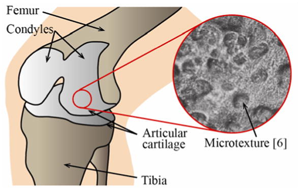
Schematic of a natural knee joint showing the articular cartilage on the condyles of the femur, articulating with the articular cartilage on the tibia. A magnified view of the surface of the articular cartilage depicts many indentations and microtexture features. The magnified view inset, obtained with a scanning electron microscope at a 220× magnification, is reproduced from Longmore and Gardner [6].
By contrast, state-of-the-art prosthetic knee joints, as introduced by Gunston in the 1960s [8, 9], consist of ultra-smooth bearing surfaces. A prosthetic knee bearing comprises a metal femoral component typically made of Cobalt-Chromium (CoCr), attached to the femur, articulating with a polyethylene tibial insert that is constrained on a tibial plateau, which is anchored in the tibia. The most common failure mechanisms of prosthetic knee joints include mechanical loosening and instability, often resulting from osteolysis (“weakening of the bone”), which is driven by a biological response to polyethylene wear particles that causes bone resorption [10]. Manufacturers of prosthetic knee joints combat implant wear by attempting to improve the mechanical properties of the polyethylene tibial insert [11] and by increasing the smoothness of the bearing surfaces, witnessed by the increased interest in ceramic prosthetic knee joints [12-14]. However, the longevity of these man-made bearing surfaces still does not replicate, or even approach that of natural articular cartilage [15]. Prosthetic knee joint designs that mimic properties of natural articular cartilage, such as the cushioned knee design proposed by Auger and Dowson [16, 17] have been attempted, but no bio-inspired design approach has been successfully implemented in a commercial product.
It is well-known that adding a specifically designed patterned microtexture to otherwise smooth bearing surfaces can increase the load-carrying capacity and lubricant film thickness between these bearing surfaces and, thus, reduce friction and wear [18, 19]. On the basis that surface microtexture improves performance of other man-made bearings and also inspired by the microtexture existing on natural articular cartilage, we hypothesize that a patterned microtexture optimized for a prosthetic knee bearing will reduce friction and wear by means of improved lubrication.
2. Theoretical model
2.1 Texture geometry and density optimization
We have implemented an elastohydrodynamic lubrication model to simulate a simplified prosthetic knee bearing. In this model, we account for axial loading and flexion/extension, which are the most important loading and kinematic components during gait. Figure 2 depicts a schematic of the model, showing a smooth, deformable surface representing the tibial insert, and a rigid microtextured surface with an array of N-by-N indentations, representing a small section of the femoral component. Each indentation is a spherical cap, i.e., a segment of a sphere (referred to as “spherical indentation” in the paper). The radius of curvature of the femoral component is several orders of magnitude larger than the size of the indentations on the microtextured surface. Thus, we can approximate the joint in the contact region as two parallel sliding surfaces in relative motion, separated by a thin layer of incompressible joint fluid of minimum thickness c. Neglecting the wedge-shaped channel between the femoral component and the tibial insert allows focusing entirely on the effect of the microtexture pattern on the lubricant film thickness. An array of 64 (N = 8) indentations is representative of the entire femoral component, because boundary effects decay quickly. While joint fluid is shear-thinning, the shear rate dependence of the viscosity decreases considerably in prosthetic joints compared to natural joints [20]. Additionally, bovine serum, which is used as an analog for joint fluid in laboratory experiments, displays Newtonian viscosity [20]. Hence, we use a constant dynamic viscosity μ = 1.0 Pa·s. The large value of μ is to ensure stability of the numerical simulation. However, the viscosity is believed to have little influence on relative performance of different microtexture designs [21]. A knee gait cycle consists of time-dependent loading, motion and lubricant film thickness [22]. We optimize the microtexture geometry for constant loading and a constant sliding velocity (U = 0.10 m/s) between the femoral component and the tibial insert. First, the optimal microtexture geometry and pattern is almost independent of the bearing sliding velocity [21], similar to the effect of lubricant viscosity. Second, in our experiments (see section 3) we impose a reciprocating motion with constant load and sliding velocity between a surrogate femoral component and tibial insert. Figure 2 shows that each spherical indentation has a radius rp and depth hp and is centered in a unit cell of width 2r1. The texture aspect ratio ε is defined as the ratio of indentation depth and diameter, and the texture density Sp is defined as the ratio of the area covered by indentations and the total bearing area. The elastic modulus of CoCr and polyethylene is ECoCr = 230 GPa and Epoly = 1 GPa, respectively [23]. The Poisson's ratio of polyethylene vpoly = 0.4 [23]. Hence, in our model we assume a rigid metal femoral component, but a polyethylene tibial insert that is subject to deformation as a result of the bearing pressure. The load-carrying capacity of the lubricant film per unit area, W, is computed as the average bearing pressure in the solution domain Ω with area A, i.e.,
Figure 2.
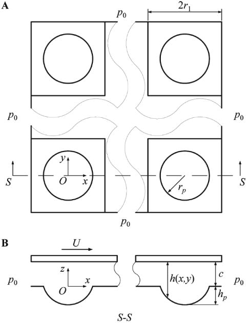
Model of a microtextured bearing with spherical indentations, (A) top view of solution domain Ω, and (B) cross-section showing the geometry of the microtexture.
| (1) |
The steady-state incompressible Reynolds equation relates the local bearing pressure p(x,y) to the local lubricant film thickness h(x,y) for given operating conditions (U, μ, W) and microtexture geometry (ε = hp/2rp and Sp = π(rp/2r1)2) [18].
| (2) |
Here,
within the local coordinate system of one unit cell. d(x,y) is the polyethylene deformation, computed from the local pressure p(x′,y′) of all (x′,y′) in the solution domain Ω.
| (3) |
Ambient pressure, p0, is maintained on all the four edges of the solution domain, as indicated in Fig. 2. The Reynolds cavitation boundary condition is enforced, which dictates that the pressure cannot drop below the ambient pressure in the cavitation region, and the pressure gradient is zero at the boundary of the cavitation region [24].
We have used a finite difference formulation in combination with the Effective Influence Newton (EIN) method [25] and the Multi-Level Multi-Integration (MLMI) method [26], to simultaneously solve Eqs. (1), (2), and (3). A uniform grid with 129 by 129 nodes per unit cell is selected based on a mesh convergence study.
2.2 Simulation results
Using this lubrication model, we have computed the geometry and density of the indentations to maximize the thickness of the lubrication film between the bearing surfaces in relative motion under a constant bearing load. Maximizing the lubricant film thickness minimizes contact between the bearing surfaces. We find that a sparse pattern of extremely shallow indentations yields optimal results. Figure 3 shows the minimum lubricant film thickness of the bearing for fixed operating conditions (μ = 1.0 Pa⋅s, U = 0.10 m/s, W = 0.5 MPa), which represent realistic in-vivo conditions, as a function of the texture aspect ratio ε and the texture density Sp. The largest minimum lubricant film thickness in the bearing occurs for 0.20 ≤ Sp ≤ 0.40 and ε ≈ 0.025. We observe that the minimum lubricant film thickness is more sensitive to the texture aspect ratio than to the texture density. Figure 3 also indicates three microtexture designs with solid white dots, which we have implemented and evaluated in experiments.
Figure 3.
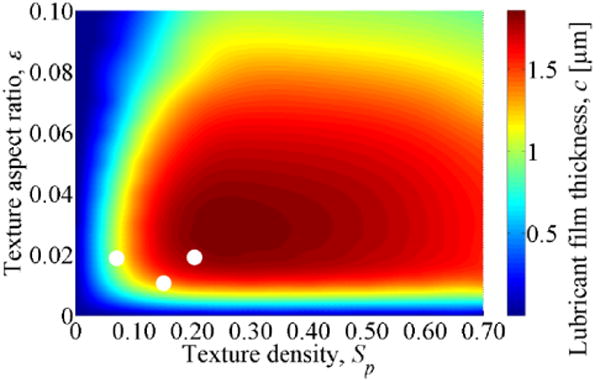
Simulated minimum lubricant film thickness of the bearing as a function of texture aspect ratio ε = hp/2rp and texture density Sp = π(rp/2r1)2, for μ = 1.0 Pa·s, U = 0.1 m/s, W = 0.5 MPa. The microtexture designs used in the experiments (section 3) are marked with solid dots.
3. Experiments
3.1 Methodology and specimens
We have implemented three different spherical microtexture designs, selected based on the simulation results (geometry indicated as solid white dots in Fig. 3), on 25 mm radius convex CoCr cylinders (ASTM 1537-F) polished to Ra = 50 nm surface roughness. The 25 mm radius of the cylinder represents the main radius of curvature of the femoral component of an average sized prosthetic knee joint. Each spherical microtexture feature has a radius rp = 50 μm and is manufactured with laser surface texturing [18]. We have verified with white light interferometry that the laser manufacturing does not alter the surface roughness of the CoCr cylinder outside the texture features. The CoCr cylinder is mated with a flat ultra-high molecular weight polyethylene (UHMWPE) specimen with a surface roughness of Ra = 500 nm. The surface finish of both bearing surfaces is similar to that of commercial prosthetic knee joints. Both specimens are shown in Fig. 4. The convex-on-flat contact in the surrogate bearing is a simplification of the complex three-dimensional convex-on-concave contact that occurs in a commercial prosthetic knee joint. Convex-on-concave contact would result in a larger contact area than convex on flat (our experiment), reducing the contact pressure. It is also noted that while with the steady-state lubrication model identical results would be obtained when placing the microtexture on the CoCr or UHMWPE specimen, in practice it is advisable to texture the CoCr specimen, since the UHMWPE is subject to wear, which could alter the microtexture geometry.
Figure 4.
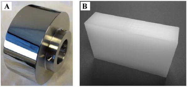
(A) CoCr cylindrical specimen, and (B) UHMWPE specimen.
Figure 5 (A) shows a schematic of the friction experiment. A CoCr cylinder rotates reciprocally according to a prescribed 1 Hz kinematic cycle over a span of θ = 90°, while pressed against a flat UHMWPE specimen with load F. This simulates the flexion/extension motion and axial loading of the knee joint, which are the primary motion and load components, respectively. Figure 5 (B) shows both specimens in contact. The contact pressure (5.6 – 11.1 MPa) between the CoCr and UHMWPE specimens is calculated using Hertz theory and falls within the range of in-vivo values [27]. The bearing surfaces are submerged in bovine serum (HyClone - 20 mg/ml protein concentration). The friction coefficient is computed from torque T and normal load F measurements, and it is compared to the friction coefficient obtained with a smooth bearing, which uses an identical UHMWPE specimen, and a CoCr cylinder without microtexture. The inset of Fig. 5 (B) shows an optical micrograph of the microtexture (rp = 50 μm). Details of the experimental apparatus are given elsewhere [28].
Figure 5.
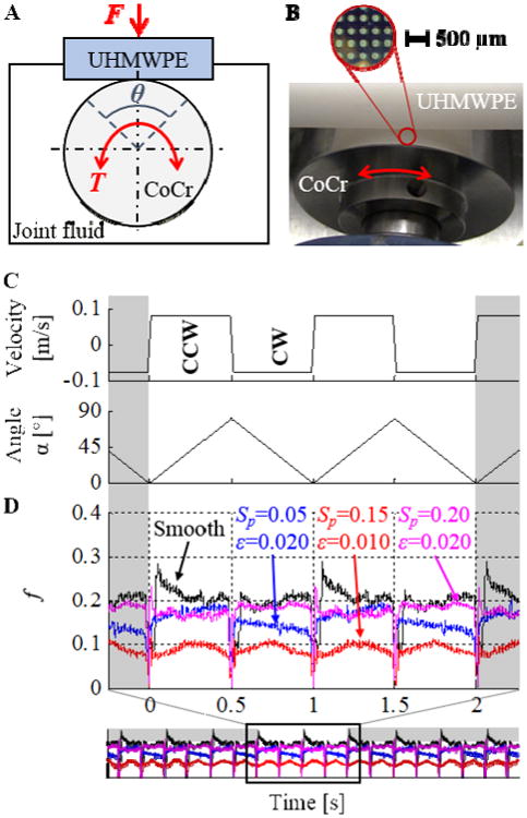
(A) Schematic of the experiment, (B) contact of the two bearing surfaces, with a magnified view (optical microscope) showing the pattern of spherical indentations (light grey circles) on the CoCr cylinder. (C) Kinematic cycle applied to the CoCr cylinder, and (D) friction coefficient f between the CoCr and UHMWPE specimens as a function of time, showing that the microtextured bearing surface outperforms the smooth bearing surface over most of the kinematic cycle. The data is extracted from a long duration test and the normal load N creates a contact pressure of 11.1 MPa.
3.2 Experimental results
Figure 5 (C) shows the kinematic cycle imposed on the CoCr specimen articulating against the stationary UHMWPE specimen, and Fig. 5 (D) depicts the resulting friction coefficient f as a function of time, for the three different microtexture designs. The two seconds of data shown are extracted from an extended-duration experiment, and illustrate the effect of the patterned microtexture on the friction coefficient. These results do not change as a function of time during the span of the experiment. In this typical experiment the contact pressure between the specimens is 11.1 MPa. We observe that the friction coefficient varies dynamically and is periodic with reversals between counter-clockwise (CCW) and clockwise (CW) rotation. Moreover, the magnitude variation during each period can be interpreted to identify the different phases of the kinematic cycle (Fig. 5 (C)). For example, f is maximum at the end and beginning, and it is minimum in the middle of each cycle, where there is constant-speed rotation and sliding (U = 0.10 m/s). For all three microtexture designs, the friction coefficient is lower than the smooth bearing pair. For the microtexture with Sp = 0.15 and ε = 0.010, the friction coefficient is approximately 50% lower than for the smooth bearing pair. This indicates that the microtexture increases the lubricant film thickness between the bearing surfaces compared to the smooth bearing pair, and that an increased portion of the bearing load is carried by the lubricant film, thereby reducing contact and, thus, friction. In addition, we observe from Fig. 5 (D) that at each reversal of sliding direction in the kinematic cycle, the friction coefficient of the microtextured bearing decreases almost instantaneously to its steady-state value, whereas that of the smooth one decreases more slowly. This shows that the microtexture enables a faster increase in the lubricant film thickness and, correspondingly, the portion of the bearing load carried by the lubricant film. Because the spacing between the CoCr and UHMWPE bearing surfaces is smallest around the start and end portions of a kinematic cycle, microtextured prosthetic knee joints yield their greatest benefit at precisely these instances, emphasizing the benefit of the microtexture during boundary lubrication. The slight increase in the friction coefficient in the middle of the kinematic cycle is likely the result of manufacturing tolerances on the shape and roundness of the specimens.
Table 1 quantifies the portion of the kinematic cycle during which each of the microtextured CoCr specimens displays a lower friction coefficient than the smooth CoCr specimen, to evaluate and compare the performance of the three microtexture geometry designs relative to each other. The results are shown for three different values of the contact pressure. In all cases, we find that the microtextured surrogate prosthetic knee joint outperforms the smooth one, providing a lower friction coefficient over approximately 73% – 100% of the kinematic cycle, depending on design and contact pressure. During the remaining part of the kinematic cycle the microtextured and smooth bearing have approximately the same friction coefficient, i.e., the smooth bearing never outperforms the microtextured one in our experiments (see also Fig. 5 (D)).
Table 1.
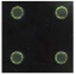
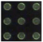
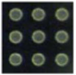
Percentage of the 1 Hz kinematic cycle during which the microtexture design outperforms the smooth bearing, for different microtexture geometries, and for different values of constant bearing contact pressure. During the remainder of the kinematic cycle, both bearings perform equally.
| Texture design | Texture parameters | Contact pressure [MPa] | ||
|---|---|---|---|---|
|
|
Sp, ε | 5.6 | 8.9 | 11.1 |
|
Sp = 0.05, ε = 0.020 | 94% | 91% | 92% |
|
Sp = 0.15, ε = 0.010 | 96% | 98% | 100% |
|
Sp = 0.20, ε = 0.020 | 91% | 73% | 85% |
3.3 Discussion
The model we have used includes several simplifying assumptions. We neglect the time-varying sliding velocity and bearing spacing experienced in prosthetic knee joints during gait, because the optimum microtexture geometry is believed to be almost independent of the bearing operating conditions. Thus, we have performed the optimization for a constant velocity and bearing load-carrying capacity, which allows using a steady-state simulation. Good agreement between the performance of the different microtexture designs in the experiments and the simulations is observed. The discrepancy between the experiments and the model prediction could originate from imperfections in the experimental environment, such as minor misalignment of the apparatus and manufacturing tolerances of the specimens and the patterned microtexture. Figure 5 (C) shows that the friction coefficient for the microtexture with Sp = 0.05 and ε = 0.020 and the microtexture with Sp = 0.20 and ε = 0.020 are almost identical in the CCW rotation but less similar in the CW rotation, which indicates slight misalignment in the experimental apparatus. This is unlikely to alter the high percentage of the kinematic cycle during which the microtextured bearings outperform the smooth bearings, but might affect the relative performance of different microtexture designs. The elastohydrodynamic lubrication model can be improved by solving the bearing pressure and spacing for the entire contact region of the prosthetic knee joint. This would improve the accuracy of the polyethylene deformation, which is dependent on the local pressure throughout the entire bearing. This would, however, result in excessive computational cost. In addition, the experimental results indicate that mixed lubrication occurs rather than full fluid lubrication, i.e., the bearing load is carried in part by the lubricant film and in part by solid-on-solid contact between the bearing surfaces. Thus, the model could also be improved by considering contact between the CoCr and UHMWPE bearing surfaces.
Several patents exist [29, 30, 31] that describe different forms of textured prosthetic joints. However, the critical difference between these patents and our work is that we attempt to use microtexture to increase the lubricant film thickness between the femoral component and the tibial insert and, thus, reduce friction. As shown in the results in Fig. 3, very shallow microtexture features are needed to accomplish this. In contrast [29, 30, 31] describe texture features meant to serve as lubricant reservoirs and wear particle traps, with a texture aspect ratio that is an order of magnitude larger than the texture features we have designed.
We have experimentally demonstrated that an engineered patterned microtexture on the surface of the femoral component can reduce friction in surrogate prosthetic knee bearings. The microtexture increases the lubricant film thickness and, thus, an increased portion of the bearing load is carried by the lubricant film, resulting in reduced contact and friction. Eventually, when applied to commercial prosthetic knee joints, the microtexture could improve longevity, which would enable younger patients to qualify for a total knee replacement surgery and, additionally, would reduce the number of revision surgeries. Contrary to the current paradigm of maximizing smoothness of prosthetic knee bearings, this insight may provide inspiration for the design of future microtextured prosthetic knee joints with increased longevity compared to the state-of-the-art.
Highlights.
We aim to use surface microtexture to reduce friction in prosthetic knee joints
A lubrication model is used to optimize the patterned microtexture
The optimum microtexture is similar to the texture of natural articular cartilage
Experiments demonstrate that microtexture reduces friction in a prosthetic joint
Acknowledgments
This work was partially funded through NSF award #1227869, NIH award #1R41AR064095-01 and a University of Utah Technology Commercialization grant. AC also acknowledges partial funding through an Undergraduate Research Opportunity (UROP) award from the University of Utah, and through the Society of Tribologists and Lubrication Engineers (STLE) E.R. Booser Presidential Award. We thank J. Speltz and Dr. R. Jacobsen from Mound Laser and Photonics Center in Kettering, OH (USA) for fabricating the microtexture on the CoCr cylinders, and Profs. J.J. Abbott and S.J. Roundy (University of Utah) for fruitful discussions.
Footnotes
Publisher's Disclaimer: This is a PDF file of an unedited manuscript that has been accepted for publication. As a service to our customers we are providing this early version of the manuscript. The manuscript will undergo copyediting, typesetting, and review of the resulting proof before it is published in its final citable form. Please note that during the production process errors may be discovered which could affect the content, and all legal disclaimers that apply to the journal pertain.
References
- 1.Ateshian GA. The role of interstitial fluid pressurization in articular cartilage lubrication. J Biomech. 2009;42(9):1163–76. doi: 10.1016/j.jbiomech.2009.04.040. [DOI] [PMC free article] [PubMed] [Google Scholar]
- 2.Bullough P, Goodfellow J. The significance of the fine structure of articular cartilage. J Bone Joint Surg B. 1968;50(4):852–7. [PubMed] [Google Scholar]
- 3.Liverpool GM, Roy S. Surface ultrastructure of mature adult human articular cartilage. J Bone Joint Surg B. 1969;51(3):529–39. [PubMed] [Google Scholar]
- 4.Clarke IC. Articular cartilage: A review and scanning electron microscope study. 1. The interterritorial fibrillar architecture. J Bone Joint Surg B. 1971;53(4):732–50. [PubMed] [Google Scholar]
- 5.Clarke IC, Schurman DJ, Amstutz HC. In vivo and in vitro comparative studies of animal articular surfaces. Ann Biomed Eng. 1975;3(1):100–10. doi: 10.1007/BF02584491. [DOI] [PubMed] [Google Scholar]
- 6.Longmore RB, Gardner DL. The surface structure of ageing human articular cartilage: a study by reflected light interference microscopy (RLIM) J Anat. 1978;126(2):353–65. [PMC free article] [PubMed] [Google Scholar]
- 7.Crockett R, Roos S, Rossbach P, Dora C, Bor W. Imaging of the surface of humand and bovine articular cartilage with ESEM and AFM. Tribol Lett. 2005;19(4):311–7. [Google Scholar]
- 8.Gunston FH. Polycentric knee arthroplasty. Prosthetic simulation of normal knee movement. J Bone Joint Surg B. 1971;53(2):272–7. [PubMed] [Google Scholar]
- 9.Gunston FH. Polycentric knee arthroplasty. Prosthetic simulation of normal knee movement: interim report. Clin Orthop Rel Res. 1973;94:128–35. [PubMed] [Google Scholar]
- 10.Bozic KJ, Kurtz SM, Lau E, Ong E, Chiu V, Vail TP, Rubash HE, Berry DJ. The epidemiology of revision total knee arthroplasty in the United States. Clin Orthop Rel Res. 2010;468(1):45–51. doi: 10.1007/s11999-009-0945-0. [DOI] [PMC free article] [PubMed] [Google Scholar]
- 11.Haider H, Weisenburger JN, Kurtz SM, Rimnac CM, Freedman J, Schroeder DW, Garvin KL. Does vitamin E-stabilized ultrahigh-molecular-weight polyethylene address concerns of cross-linked polyethylene in total knee arthroplasty. J Arthroplasty. 2012;27(3):461–469. doi: 10.1016/j.arth.2011.03.024. [DOI] [PubMed] [Google Scholar]
- 12.Hernigou P, Nogier A, Manicom O, Poignard A, De Abreu L, Filippini P. Alternative femoral bearing surface options for knee replacement in young patients. Knee. 2004;11(3):169–72. doi: 10.1016/j.knee.2004.04.001. [DOI] [PubMed] [Google Scholar]
- 13.Bal BS, Greenberg DD, Buhrmester L, Aleto TJ. Primary TKA with a zirconia ceramic femoral component. J Knee Surg. 2006;19(2):89–93. doi: 10.1055/s-0030-1248085. [DOI] [PubMed] [Google Scholar]
- 14.Oonishi H, Ueno M, Kim SC, Oonishi H, Iwamoto M, Kyomoto M. Ceramic versus cobalt-chrome femoral components; wear of polyethylene insert in total knee prosthesis. J Arthroplasty. 2009;24(3):374–82. doi: 10.1016/j.arth.2007.10.021. [DOI] [PubMed] [Google Scholar]
- 15.Kurtz SM, Ong K, Lau E, Mowat F, Halpern M. Projections of primary and revision hip and knee arthroplasty in the United States from 2005 to 2030. J Bone Joint Surg B. 2007;89(4):780–5. doi: 10.2106/JBJS.F.00222. [DOI] [PubMed] [Google Scholar]
- 16.Auger DD, Dowson D, Fisher J. Cushion form bearings for total knee joint replacement Part 1: design, friction and lubrication. Proc Inst Mech Eng H. 1995;209(2):73–81. doi: 10.1243/PIME_PROC_1995_209_323_02. [DOI] [PubMed] [Google Scholar]
- 17.Auger DD, Dowson D, Fisher J. Cushion form bearings for total knee joint replacement Part 2: wear and durability. Proc Inst Mech Eng H. 1995;209(2):83–91. doi: 10.1243/PIME_PROC_1995_209_324_02. [DOI] [PubMed] [Google Scholar]
- 18.Etsion I. State of the art in laser surface texturing. J Trib T ASME. 2005;127(1):248–53. [Google Scholar]
- 19.Qiu M, Minson BR, Raeymaekers B. The effect of texture shape on the friction coefficient and stiffness of gas lubricated parallel slider bearing. Tribol Int. 2013;67:278–288. [Google Scholar]
- 20.Mazzucco D, McKinley G, Scott RD, Spector M. Rheology of joint fluid in total knee arthroplasty patients. J Orthop Res. 2002;20(6):1157–63. doi: 10.1016/S0736-0266(02)00050-5. [DOI] [PubMed] [Google Scholar]
- 21.Shinkarenko A, Kligerman Y, Etsion I. The effect of surface texturing in soft elastohydrodynamic lubrication. Tribol Int. 2009;42(2):284–92. [Google Scholar]
- 22.ISO standard 14243-1:2009 Implants for surgery - Wear of total knee-joint prostheses, Part 1: Loading and displacement parameters for wear-testing machines with load control and corresponding environmental conditions for test.
- 23.Mattei L, Di Puccio F, Piccigallo B, Gulli E. Lubrication and wear modelling of artificial hip joints: A review. Tribol Int. 2011;44(5):532–49. [Google Scholar]
- 24.Pinkus O, Sternlicht B. Theory of hydrodynamic lubrication. McGraw-Hill; New York: 1961. [Google Scholar]
- 25.Jagatia M, Jin ZM. Elastohydrodynamic lubrication analysis of metal-on-metal hip prostheses under steady state entraining motion. P I Mech Eng H. 2001;215(6):531–41. doi: 10.1243/0954411011536136. [DOI] [PubMed] [Google Scholar]
- 26.Brandt A, Lubrecht AA. Multilevel matrix multiplication and fast solution of integral equations. J Comput Phys. 1990;90(2):348–70. [Google Scholar]
- 27.Szivek JA, Anderson PL, Benjamin JB. Average and peak contact stress distribution evaluation of total knee arthroplasties. J Arthroplasty. 1996;11(8):952–63. doi: 10.1016/s0883-5403(96)80137-9. [DOI] [PubMed] [Google Scholar]
- 28.Chyr A, Sanders AP, Raeymaekers B. A hybrid apparatus for friction and accelerated wear testing of total knee replacement bearing materials. Wear. 2013;308(1):54–60. [Google Scholar]
- 29.U.S. Patent 6,045,581. Implantable prosthesis having textured bearing surfaces. 2000 Apr 4;
- 30.U.S. Patent 6,425,921. Sliding partners for artificial joint implants. 2002 Jul 30;
- 31.U.S. Patent 8,323,349. Textured surface for orthopedic implants. 2012 Dec 4;


