Abstract
Access to the cochlea requires drilling in close proximity to bone-embedded nerves, blood vessels, and other structures, the violation of which can result in complications for the patient. It has recently been shown that microstereotactic frames can enable an image-guided percutaneous approach, removing reliance on human experience and hand–eye coordination, and reducing trauma. However, constructing current microstereotactic frames disrupts the clinical workflow, requiring multiday intrasurgical manufacturing delays, or an on-call machine shop in or near the hospital. In this paper, we describe a new kind of microsterotactic frame that obviates these delay and infrastructure issues by being repositionable. Inspired by the prior success of bone-attached parallel robots in knee and spinal procedures, we present an automated image-guided microstereotactic frame. Experiments demonstrate a mean accuracy at the cochlea of 0.20 ± 0.07 mm in phantom testing with trajectories taken from a human clinical dataset. We also describe a cadaver experiment evaluating the entire image-guided surgery pipeline, where we achieved an accuracy of 0.38 mm at the cochlea.
Keywords: Bone-attached robot, cochlear implant, Gough–Stewart platform, microtable, minimally invasive surgery (MIS), parallel robot
I. Introduction
Cochlear implants are electronic devices that can restore hearing to individuals who have severe or total hearing loss. In a cochlear implant system, an external microphone and sound/speech processing unit transmit signals through the skin to a subcutaneous receiver, which applies electrical impulses to an electrode array implanted inside the cochlea. This array stimulates intracochlear nerves, resulting in sound perception.
The current surgical procedure for cochlear implantation (CI) requires mastoidectomy, in which an open cavity approximately 35 mm deep is created in the temporal bone behind the ear using a hand-held surgical drill. During the procedure several sensitive structures embedded in the bone must be identified and preserved, while the surgical drill passes within a few tenths of a millimeter of them. These include the facial nerve, damage to which results in ipsilateral facial paralysis, and the chorda tympani, damage to which results in ipsilateral loss of taste in the tongue. These two nerves are separated by approximately 2 mm at the facial recess, through which the drill and electrode array must pass. To prevent injury, the surgeon must relate a 3-D mental map of critical subsurface features to anatomical landmarks exposed during drilling. To accomplish this he/she must rely on hand–eye coordination and memory to avoid accidentally damaging these nerves or encroaching on the ear canal, which can lead to chronic infection. To potentially enhance patient safety and reduce trauma, it is desirable to automate this procedure, removing reliance on human hand–eye coordination, spatial reasoning, and memory. Percutaneous CI (PCI) is a new surgical procedure designed to achieve this using image guidance, but the procedure relies on the availability of a microstereotactic frame custom made for each patient to guide the drill along a linear trajectory from the lateral skull to the cochlea [1], [2].
Microstereotactic frames such as the STarFix (FHC, Inc., Bowdoin, ME) offer the prospect of submillimetric accuracy. They are rigid fixtures that are specifically manufactured for each patient and each clinical target, which are anchored directly to the bone using bone screws. The STarFix has achieved accuracies of 0.42 ± 0.15 mm deep in the brain [3]. However, the drawback of using the STarFix is a disruption of clinical workflow. The procedure for obtaining a STarFix is to implant anchors into the skull of the patent, scan the patent [e.g., using computed tomography (CT)], send the image data to the manufacturer, and wait 2–4 days while the device is manufactured and transported to the hospital. Only then can the surgery take place.
To address this time delay, an alternate type of microstereotactic frame, known as a microtable, has been developed by Labadie et al. at Vanderbilt University, Nashville, TN [4]. This frame can be manufactured in less than 5 min using a standard computer numeric control (CNC) machine, followed by autoclave sterilization. However, it also requires a machine shop and machinist close to the operating room and on call at all times when a PCI surgery may occur.
PCI begins with placement of three self-tapping metal anchors with spherical heads into the temporal bone. A CT scan of the temporal bone region, including the anchors, is then acquired. Custom planning software is used to automatically segment the structures of the inner ear [5], [6], determine an optimal trajectory to the cochlea [7], and localize the centers of the spherical heads in image space. Next, a customized microtable is automatically designed by a custom software program, using the locations of the spheres and desired target as inputs.
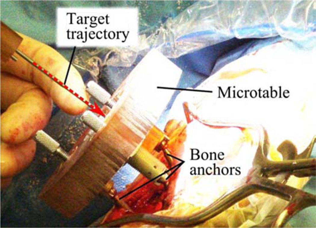
The microtable itself consists of a flat slab of Ultem supported by three legs that attach to the bone-implanted anchors. The microtable is manufactured using a CNC milling machine, and then is sterilized and attached to the bone anchors as shown in Fig. 1. A mechanical coupling allows for secure attachment of a drill [4] and then a robotic [8] or manual [9] implant insertion tool, each of which access the skull through a hole machined in the Ultem. A targeting accuracy of 0.37 ± 0.18 mm [4] has been demonstrated with the microtable. PCI has also been validated on human cadaver temporal bone specimens [10]. Though PCI has not yet been used for full cochlear implant surgery in a live patient, it is currently being clinically evaluated in human cases [1], and trajectories from these human cases comprise the clinical dataset we use in this paper. We hypothesize that PCI will reduce invasiveness, enhance patient safety, and have the added advantage of reducing operating time from a current average of 170 min [11] to a duration consistently below 60 min.
Fig. 1.
Microtable, a microstereotactic frame, mounted on a patient during the clinical validation of PCI, which is a minimally invasive technique for CI. Though a skin incision was required for the clinical validation protocol pictured, in clinical practice the drill is intended to pass through a small puncture in the skin, with no incision required.
While experimental results for PCI are promising and it may be feasible to install miniature machine shops in some hospitals, it would be ideal to remove the need for the machine shop and a machinist altogether. This is the purpose of the automated image-guided microseterotactic (AIM) frame that is the subject of this paper. The AIM frame is a bone-attached miniature parallel robot. It was inspired by prior examples of bone-attached robots in medicine, particularly the pioneering work of Shoham et al. [12], who introduced a bone-attached parallel robot for orthopedic and spinal procedures. The device was later commercialized as the Mazor SpineAssist robot [13]. While neurosurgery has been attempted with this robot [14], [15], sufficient submillimetric accuracy and precision for PCI surgery has not yet been achieved. Subsequent to Shoham et al.’s work, bone-attached parallel robots have been developed for knee arthroplasty by Plaskos et al. [16], Song et al. [17], and Wolf et al. [18]. Parallel robots have been favored for bone-attached surgery due to their stiffness, high payload-to-weight ratio, and potential for high positioning accuracy.
II. Surgical workflow
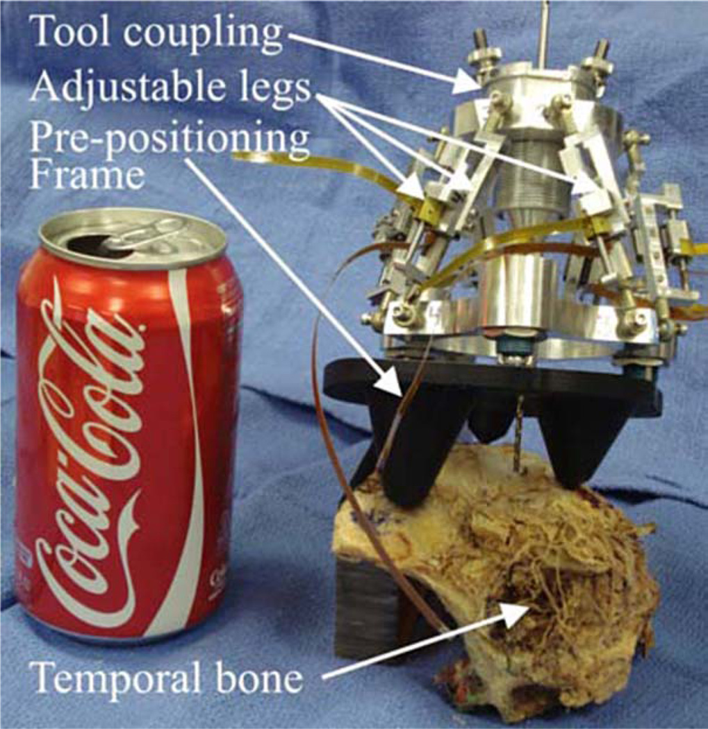
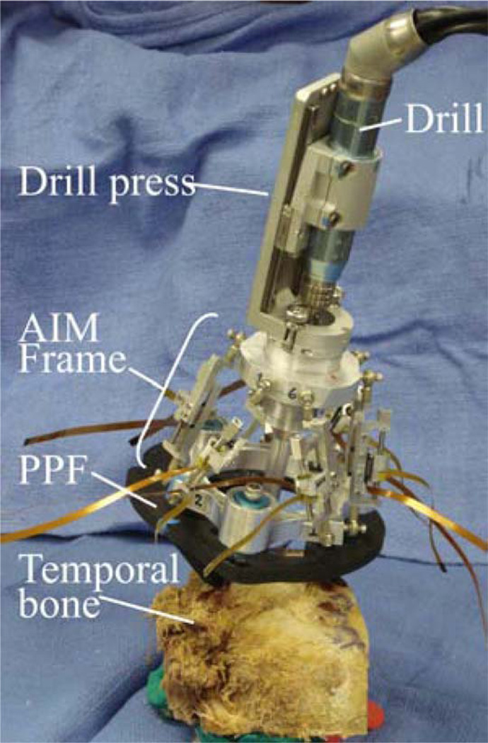
Our current AIM Frame prototype, shown in Fig. 2, consists of a robot that attaches to a rigid mounting platform that we call a prepositioning frame (PPF). The PPF attaches directly to the skull with bone anchoring screws. Electronic control circuitry is housed in an separate enclosure that is connected to the robot with detachable cables.
Fig. 2.
AIM frame prototype attached to a human cadaver temporal bone specimen.
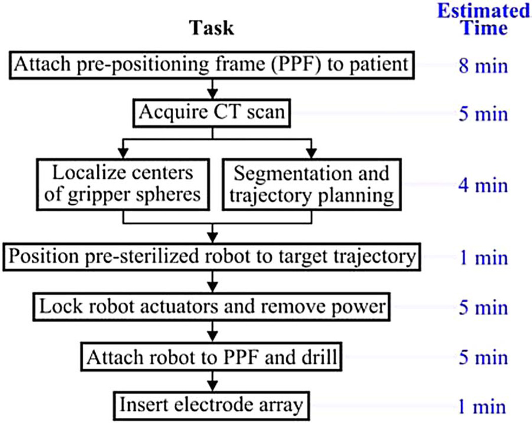
The surgical workflow for PCI with an AIM Frame is summarized in Fig. 3. First, the PPF is attached to the skull using bone screws. Next, a CT scan is acquired that enables identification of both patient anatomy and the three metal spheres on the top of the PPF. Software previously developed for PCI path planning (discussed in Section I) is then used to segment relevant anatomy, localize the centers of the spheres, and plan a safe trajectory to the cochlea relative to the sphere locations. The AIM frame (which is not yet attached to the PPF) is then configured using its actuators so that a tool attached to its top platform will be aligned with the desired trajectory. The robot’s actuators are then locked and the robot disconnected from its power and control electronics. The robot is then attached securely to the spheres on top of the PPF, as shown in Fig. 2. The assembled system functions as a customized, rigid microstereotactic frame, and a surgical drill and implant insertion tool are attached to it to perform the surgery.
Fig. 3.
Surgical workflow for PCI using the AIM frame.
III. AIM Frame Robot Design
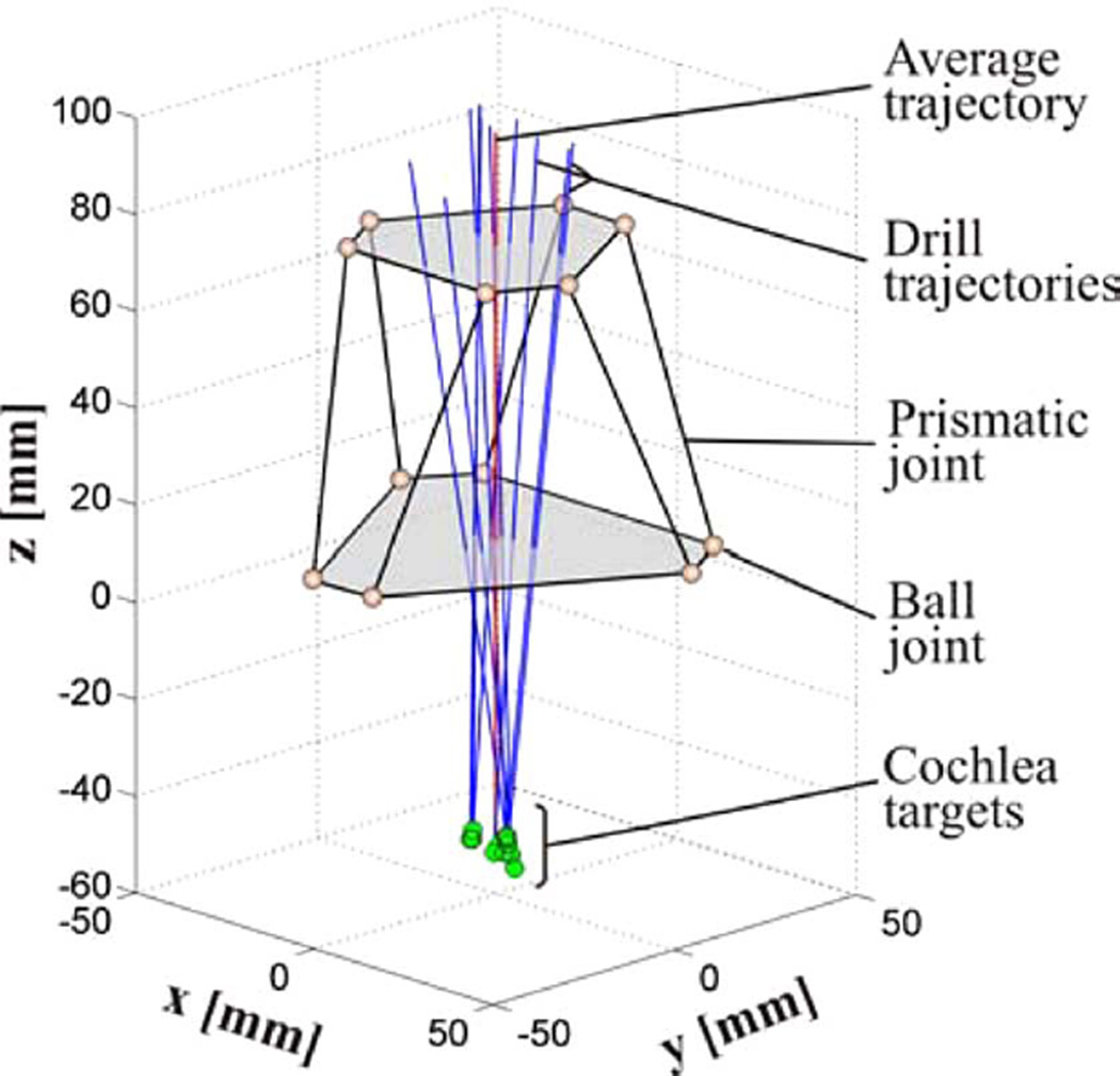
We began design of the AIM frame by selecting the Gough–Stewart parallel robot architecture. This architecture was selected primarily for ease of implementation, since it is a standard type of parallel robot. Our prototype consists of two aluminum platforms connected by six actuated prismatic joints as shown in Fig. 2. The ends of each prismatic joint are passive ball joints, arranged to form the vertices of a hexagon on each platform. To design the AIM Frame, i.e., choose robot dimensions and PPF geometry, we first obtained a clinical dataset consisting of ten patient CT scans from prior PCI clinical validation studies [1], described in Section I. The total material cost for the AIM frame prototype (not including the control PC) was approximately $4 500.
A. Clinical Dataset Processing: Obtaining Drill Trajectories
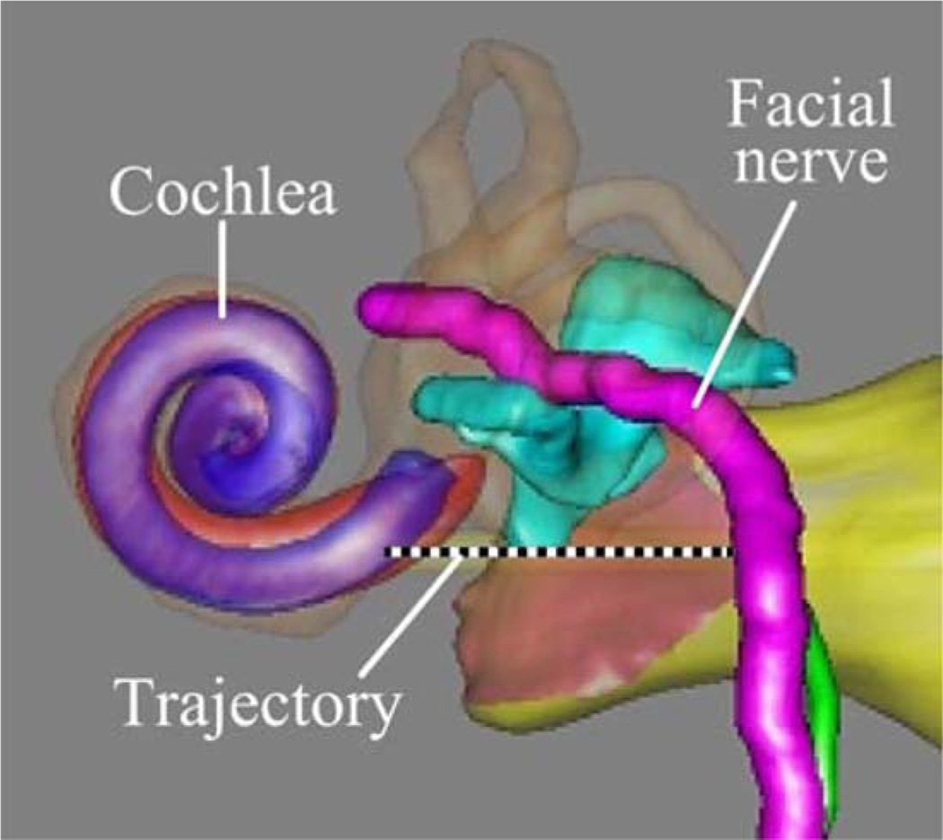
The clinical data consisted of CT scans of ten patients that were collected after the spherical bone anchors had been attached. Each patient CT scan was processed using an atlas-based approach to automatically segment the structures of the ear and identify a safe trajectory for PCI [5]–[7]. An example computer rendering of the results of this segmentation and the planned trajectory is shown in Fig. 4.
Fig. 4.
Patient CT scans are processed by custom software that automatically segments critical structures and calculates an optimally safe trajectory to the cochlea. The output of the segmentation is shown here.
All the ten trajectories were transformed to a common coordinate system defined by the atlas, in order to define the necessary workspace of the AIM frame. This transformation was achieved by means of two rigid registrations, both accomplished using the standard mutual information method [19]. The first roughly aligned the head in the patient CT scan with the head in the atlas. The ear region was then cropped in the two CT scans and a second rigid registration was performed to refine the alignment of this cropped region of interest. The result of this process was a collection of clinical trajectories in the same coordinate frame, which can be used to determine the PPF design and the AIM frame workspace (see Fig. 5).
Fig. 5.
Schematic diagram of the AIM frame with ten PCI trajectories from prior microtable clinical trials. The robot is oriented by a PPF (not shown), so that that its nominal trajectory is centrally located with respect to the clinical trajectories.
B. PPF
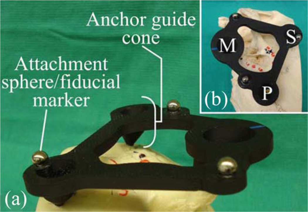
The geometry of the PPF is selected to align the nominal robot trajectory (i.e., the trajectory when all AIM Frame legs are equal lengths and located at the middle of their travel ranges), with the average trajectory in the clinical dataset. The prototype PPF used in the initial experiments described in this paper is shown in Fig. 6. It was fabricated from acrylonitrile butadiene styrene, though in a future clinical version we intend to replace this material with a sterilizable, radiolucent material such as Ultem. The robot can be attached to the spheres on top of the PPF using the gripping mechanism described in [4]. The same spheres also serve as fiducial markers for performing a point-based rigid registration of the CT image space to the robot’s coordinate frame.
Fig. 6.
(a) Oblique and (b) top view of a PPF prototype attached to the left ear region of a skull, showing the mastoid M, superior S, and posterior P bone screw locations. The PPF is used to orient the attached robot for efficient utilization of its workspace.
C. Size of Robot Versus Number of PPFs
There is a tradeoff to be considered between the size of the robot and the number of different PPFs one chooses to design. It would be ideal to have just one PPF, but it would also be ideal to have a very small and lightweight robot—both make the system easier to use for the clinical team. However, for a given robot design and desired workspace, these two goals may not be simultaneously achievable. If multiple PPFs are included in the system, we believe that a small number (e.g., 3–5) will be possible to include without significant detriment to ease of use. All would be presterilized and available in the operating room. They could be color coded, and the correct one selected by planning software.
We require more clinical data before we can conclusively characterize the spread of necessary clinical trajectories and determine the optimal size of robot versus number of PPFs. In our initial prototype, described in this paper, we began by designing a compact robot, and proceeded by determining how many PPFs would be necessary to fully cover our clinical dataset. For our prototype, the number of necessary PPFs was three. This was due largely to leg encoder length limits as discussed in the following section. In future prototypes, we intend to devise alternate encoding methods to allow larger leg displacements, which may make it possible to use a single PPF without requiring a large robot.
D. Actuators and Encoders
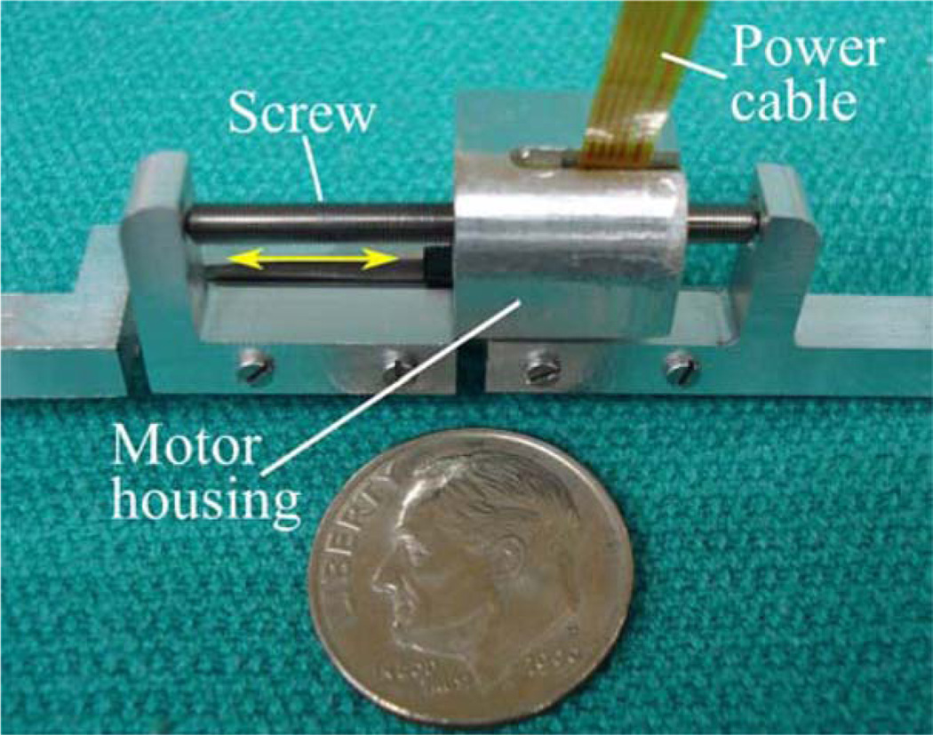
The robot is actuated by six Squiggle SQL 3.4 linear piezoelectric motors (New Scale Technologies, Victor, NY) [20]. These motors were chosen for their high power-to-weight ratio, small size, and high resolution. Each motor weighs 1.2 g and can generate bidirectional motion with 2-N maximum output force. The stator package is approximately 3.4 mm × 3.4 mm × 10 mm. The motors can extend and retract at 4 mm/s while exerting 1 N. We estimate that the required positioning time for PCI trajectories will be under 5 s.
Each motor is enclosed in an aluminum fixture forming a prismatic joint that may be extended and retracted by the motor, as shown in Fig. 7. The fixture also houses a TRACKER Position Sensor (New Scale Technologies, Victor, NY) to measure leg displacement. The TRACKER is a hall effect-based linear encoder with a minimum resolution of 0.5 µm. We custom manufactured magnets for each TRACKER sensor to measure displacements up to 13.3 mm.
Fig. 7.
One of six motor-actuated prismatic joints, shown next to a U.S. dime. Screw rotation causes linear translation of the motor housing, which is attached to a ball joint on the robot’s top platform.
The suitability of these motors for direct exposure to repeated sterilization is not known, though we have subjected one motor to a standard autoclave sterilization cycle (270.0 °F, 4-min sterilization time, 1 h, 13-min total cycle time), and another to ethylene oxide gas sterilization (130 °F, total cycle time of 14 h, 59 min). Qualitatively, we did not observe any degradation of performance for either motor following sterilization.
E. Control System
Custom-written control software programmed in MATLAB (Mathworks, Natick, MA) calculates a target pose for the robot’s top platform using trajectory data obtained using the planning software described in Section I. The control software then plans a path from the robot’s home pose to the target pose, and corresponding trajectories for each leg are calculated using an inverse kinematic model [21]. The user enters the leg trajectory data into New Scale Pathway software (New Scale Technologies, Victor, NY) that drives the motors. Each motor is powered by a MC-1100 motor controller (New Scale Technologies, Victor, NY). The motor controllers are contained in an electronics enclosure and connected via USB cables to a PC. The robot may be detached from the control electronics for sterilization (it is not necessary to sterilize the electronics enclosure, since it is sufficiently remote from the patient and can be covered in a sterile plastic bag in the operating room).
F. Attachment of Surgical Tools
The top platform of the robot includes a mechanical coupling that enables rapid tool changes with accurate mating. During PCI surgery two tools will be attached: a drill press [2] and a cochlear implant insertion tool [9]. Thumbscrews allow the drill press and insertion tool to be firmly coupled to the mating fixture on the top plate of the AIM frame. Attached to the bottom of this plate is a bushing that supports the drill bit up to the skull entry point, preventing drill bit wander during drilling. The AIM frame with surgical drill attached is shown in Fig. 8.
Fig. 8.
AIM Frame with attached drill press.
IV. Experimental Results
A. Free-Space Accuracy Experiment
To evaluate the targeting accuracy of the AIM frame robot, we used the virtual target method introduced by Balachandran et al. [3], in which targets are represented as points in space relative to a coordinate frame defined by fiducial markers embedded on a phantom. The ten trajectories obtained from the clinical dataset were used as targets, as partitioned for use with the three PPF’s as described in Section III-C.
The phantom, shown in Fig. 9, was milled from an acrylic block with overall dimensions of 6 in × 6 in × 1.5 in. Three 0.25 in diameter steel spheres were embedded on the phantom to represent the PPF spheres and 19 steel spheres of 3-mm diameter were embedded on the phantom to act as fiducial markers. The locations of the centers of all the steel spheres were measured using a FARO GagePlus Measurement System (FARO Technologies Inc., Lake Mary, FL). The ten target trajectories were then defined relative to a coordinate frame established by the locations of the fiducial markers in the FARO space.
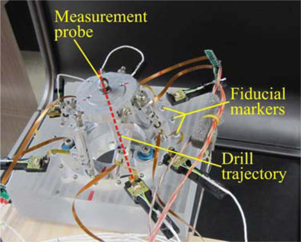
Fig. 9.
Phantom used for measuring the accuracy of the AIM frame in free space. Fiducial markers were embedded in the phantom to define the virtual targets and facilitate accurate registration.
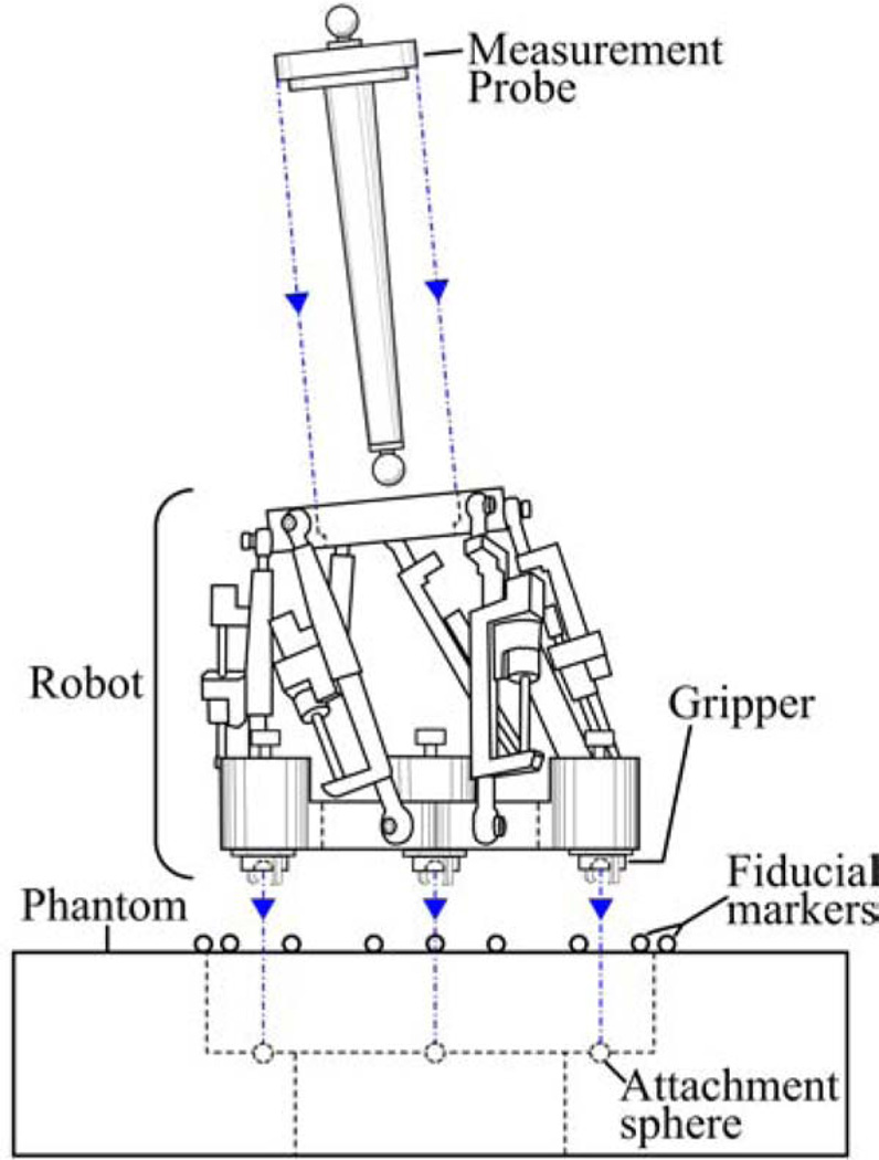
The AIM frame was attached to the phantom, and a measurement probe consisting of a rod with spherical steel ends was affixed to the top platform, as shown in Fig. 10. This probe was used to represent the drill axis, and the bottom sphere was located 76 mm along the drill trajectory, as measured from the center of the top platform. Using the locations of the spheres, as measured by the FARO, the drill axis can be defined, and the final position of the drill bit at the cochlea (at the planned depth) in CT space can be extrapolated.
Fig. 10.
Schematic detail of experimental apparatus used to measure the accuracy of the AIM frame in free space.
Each trial began with the robot in a neutral pose. The robot was then positioned to a target trajectory, and then returned to the same neutral pose in preparation for the subsequent trial. A CT scan of the phantom with attached robot was acquired at each target and neutral pose using an xCAT ENT CT scanner (Xoran Technologies, Ann Arbor, MI), which provides scans with an isotropic voxel volume of 0.4 mm3. Each target position was repeated three times, to obtain a total of 30 scans.
To measure the accuracy of the robot, the fiducial spheres on the phantom and the spheres on the probe were first localized in each CT scan. Fiducial locations in the CT space and FARO space were then registered using a rigid, point-based registration method [22]. The extrapolated drill tip location in the CT space was then transformed to the FARO space, and the targeting error was computed as the distance between this transformed point and the desired target defined in the FARO space.
The targeting error, also known as target registration error, was measured for each trial as described earlier, and the mean targeting error due to the AIM frame robot was found to be 0.20 mm, with a standard deviation of 0.07 mm.
B. Cadaver Drilling Experiment
To validate the performance of the entire AIM frame system, we performed a drilling experiment on a cadaveric temporal bone specimen. First, a PPF was fabricated for the specimen and then attached to the bone. The lengths of the PPF legs, measured perpendicularly to the plane described by the centroids of the fiducial spheres, were 31.6 mm (mastoid), 40.9 mm (superior), and 18.8 mm (posterior). Using the xCAT scanner, the bone with the PPF attached was then scanned. The scan was then segmented, the fiducials located, and the drill trajectory selected by the segmentation/planning software described in Section I. The AIM frame legs were then adjusted to the corresponding lengths, the legs locked using set screws, and the AIM frame detached from the control circuitry, the surgical drill attached to the AIM Frame, and AIM frame and mounted to the PPF. Fig. 8 shows the AIM frame with the drill press attached to the bone.
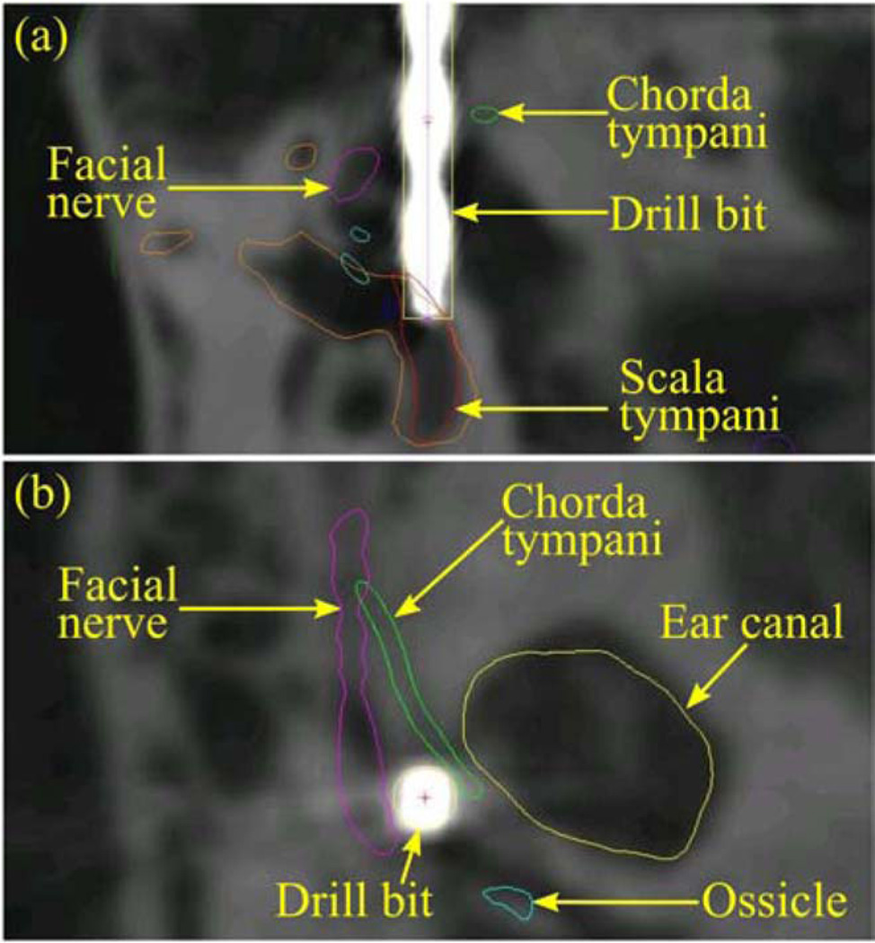
The trajectory length of 148 mm determined by the control/ planning software was then used to set a mechanical stop on the drill press. A 5/64 in diameter twist drill bit with a 118° point angle was locked into a surgical drill (Anspach Corporation, Palm Beach Gardens, FL). Drilling was performed at approximately 30,000 revolutions per minute, and was completed in 1 min, 26 s. A final CT scan was acquired of the bone with the PPF still attached and with the drill bit in the drilled hole to evaluate the drilling performed, as shown in Fig. 11. In this postdrill CT, the spheres on the PPF were automatically localized and the drill tip was manually identified. The sphere locations were used to register the predrill CT to this postdrill CT via point-based registration [22]. The planned trajectory in the predrill CT was transformed to the postdrill CT using this registration. The targeting error, which is the distance between the planned cochlear target and the drill tip, was determined to be 0.38 mm.
Fig. 11.
Two views of the postdrill CT scan, with the drill bit representing the path achieved by the AIM frame.
V. Conclusion and Future Work
In this paper, we investigated robot-assisted cochlear implant surgery. This surgery can also be approached using serial industrial robots [23], [24], but targeting errors are not yet low enough for clinical deployment [24]. Advantages of bone-attached parallel robots are that they are less obtrusive in the operating room, do not require head fixation or optical tracking, and parallel robots are known for their high stiffness and accuracy.
We have presented a bone-attached parallel robot that has an accuracy similar to microstereotactic frames, while retaining the adjustability of traditional stereotactic frames. The device simplifies the workflow of microstereotactic surgery (and specifically PCI surgery), by eliminating the need for a machine shop in the hospital or alternatively a 2–4 day delay between bone-implanted fiducial placement and surgery to have the fixture fabricated off-site. We believe this elimination of delay and infrastructure will be a key advancement for widespread deployment of the PCI technique in the future.
However, some additional work is needed before this can happen. We plan to investigate longer linear encoders to increase the travel lengths of each leg. We are currently accruing additional clinical trajectories as human microtable cases are conducted, and we intend to use these to evaluate the necessary workspace of the AIM Frame together with the optimal number of PPFs. We will evaluate these on a statistical basis such that we can be confident that the AIM frame will account for patient to patient variability in target and anchor locations. After accomplishing this, we intend to perform a clinical evaluation of the AIM frame, using methods similar to those presently being used in PCI clinical trials.
More generally, we believe that the AIM frame concept will be advantageous for other intracranial procedures requiring high positional accuracy. Examples include petrous apex drainage, mastoidectomy, and deep brain simulation. Some of these (e.g., petrous apex drainage) will be similar to PCI in that they will involve access to a specific point in image space via a straight-line drill trajectory, and in these an AIM frame would work in a conceptually similar way to what we have described in this paper for PCI. However, some future procedures (e.g., mastoidectomy and deep brain stimulation) may require that the AIM frame be actively moved during surgery to machine bone or realign a surgical tool based on intraoperative feedback. These examples indicate the potential of the AIM frame concept to assist with diverse future clinical tasks in intracranial surgery. Thus, we view the initial feasibility study for PCI presented in this paper to be a first step toward a family of highly accurate, yet adjustable, AIM frame guidance fixtures for a variety of intracranial image-guided surgical procedures.
Acknowledgments
The work was supported by the National Institute On Deafness and Other Communication Disorders under Award R01DC008408 and Award R01DC010184. The content is solely the responsibility of the authors and does not necessarily represent the official views of the National Institute On Deafness and Other Communication Disorders or the National Institutes of Health.
Biographies

Louis B. Kratchman (S’09) received the B.S. degree in mechanical engineering in 2009 and the B.A. degree in psychology in 1998 both from the University of Michigan, Ann Arbor, MI. He joined the Medical and Electromechanical Design Laboratory at Vanderbilt University, Nashville, TN, in 2009, where he is currently working toward the Ph.D. degree in mechanical engineering.
His research interests include medical robotics, parallel robots, and image-guided surgery.

Grégoire S. Blachon received a Licence Profesionelle in composite products engineering from the University of the Mediterranean Aix-Marseille II, Marseille, France, in 2009.
Since March 2009, he has been with the Computer-Assisted Otologic Surgery Laboratory, Vanderbilt University, Nashville, TN, designing and developing several tools for minimally invasive cochlear implant surgery. His interests include the computer-aided design and experimental validation of surgical tools.

Thomas J. Withrow received the S.B. degree in engineering science with a concentration in biomedical engineering from Harvard University, Cambridge, MA, in 2000. He completed the M.S.E. degree in biomedical engineering in 2001 and the M.S.E. in mechanical engineering in 2002, and the Ph.D. degree in biomedical engineering in 2005 all from the University of Michigan, Ann Arbor, MI.
He is currently an Assistant Professor of the Practice of Mechanical Engineering, Vanderbilt University, Nashville, TN. His current research involves surgical robotics and image-guided surgery—especially with neurological targets. His research interests also include mechatronic and robotic design and development, injury biomechanics, and the biomechanics of injury prevention.

Ramya Balachandran (M’09) received the B.E. degree in computer science from the University of Madras, Chennai, India, in 2001, and the M.S. and Ph.D. degrees in computer science from Vanderbilt University, Nashville, TN, in 2003 and 2008, respectively.
She is currently a Research Assistant Professor in the Department of Otolaryngology, Vanderbilt University School of Medicine, Nashville. Her research interests include development and validation of image-guided systems for otologic surgery and neurosurgery, point-based rigid registration, image-guided surgery, and robotic surgery.
Dr. Balachandran is a member of the IEEE Women in Engineering, and the SPIE.

Robert F. Labadie received the B.S. degree in mechanical engineering from the University of Notre Dame, Notre Dame, IN, in 1988, the Ph.D. degree in bioengineering and the M.D. degree from the University of Pittsburgh, Pittsburgh, PA in 1995 and 1996, respectively.
He is currently an Associate Professor in the Department of Otolaryngology/Head and Neck Surgery, Vanderbilt University Medical Center, Nashville, TN. He has a joint appointment in the Department of Biomedical Engineering, Vanderbilt University. His clinical specialty is otology, with emphasis on surgical rehabilitation of the hearing impaired, including cochlear implantation. He is the author of more than 75 peer-reviewed papers, has presented his research nationally and internationally, and has ongoing National Institutes of Health grant support to study image-guided otologic surgery, including cochlear implantation.
Dr. Labadie is a Member of the American Academy of Otolarynogology-Head and Neck Surgery, the American Otological Society, American Neurotology Society, and the Triological Society.

Robert J. Webster III (S’97–M’08) received the B.S. degree in electrical engineering from Clemson University, Clemson, SC, in 2002 and the M.S. and Ph.D. degrees in mechanical engineering from the Johns Hopkins University, Baltimore, MD, in 2004 and 2007, respectively.
In 2008, he joined the Faculty of Vanderbilt University, Nashville, TN, as an Assistant Professor of mechanical engineering, where he currently directs the Medical and Electromechanical Design Laboratory. His current research interests include medical robotics, image-guided surgery, and continuum robotics.
Dr. Webster is a recipient of the IEEE Volz award for Ph.D. thesis impact, and the NSF CAREER Award in 2011.
Footnotes
Color versions of one or more of the figures in this paper are available online at http://ieeexplore.ieee.org.
Contributor Information
Louis B. Kratchman, Email: lou.kratchman@vanderbilt.edu, Department of Mechanical Engineering, Vanderbilt University, Nashville, TN 37235 USA.
Grégoire S. Blachon, Email: gregoire.s.blachon@vanderbilt.edu, Department of Otolaryngology, Vanderbilt University Medical Center, Nashville, TN 37232 USA.
Thomas J. Withrow, Email: thomas.j.withrow@vanderbilt.edu, Department of Mechanical Engineering, Vanderbilt University, Nashville, TN 37235 USA.
Ramya Balachandran, Email: ramya.balachandran@vanderbilt.edu, Department of Otolaryngology, Vanderbilt University Medical Center, Nashville, TN 37232 USA.
Robert F. Labadie, Email: robert.labadie@vanderbilt.edu, Department of Otolaryngology, Vanderbilt University Medical Center, Nashville, TN 37232 USA.
Robert J. Webster, III, Email: robert.webster@vanderbilt.edu, Department of Mechanical Engineering, Vanderbilt University, Nashville, TN 37235 USA, and also with with the Department of Otolaryngology, Vanderbilt University Medical Center, Nashville, TN 37232 USA.
References
- 1.Labadie RF, Balchandran R, Mitchell JE, Noble JH, Majdani O, Haynes DS, Bennett ML, Dawant BM, Fitzpatrick JM. Clinical validation study of percutaneous cochlear access using patient-customized microstereotactic frames. Otol. Neurotol. 2010;31(no. 1):94–99. doi: 10.1097/MAO.0b013e3181c2f81a. [DOI] [PMC free article] [PubMed] [Google Scholar]
- 2.Balachandran R, Mitchell JE, Blachon GS, Noble JH, Dawant BM, Fitzpatrick JM, Labadie RF. Percutaneous cochlear implant drilling via customized frames: An in vitro study. Otolaryngol.-Head Neck Surg. 2010;142(no. 3):421–426. doi: 10.1016/j.otohns.2009.11.029. [DOI] [PMC free article] [PubMed] [Google Scholar]
- 3.Balachandran R, Mitchell JE, Dawant BM, Fitzpatrick JM. Accuracy evaluation of microTargeting platforms for deep-brain stimulation using virtual targets. IEEE Trans. Biomed. Eng. 2009 Jan;56(no. 1):37–44. doi: 10.1109/TBME.2008.2002110. [DOI] [PMC free article] [PubMed] [Google Scholar]
- 4.Labadie RF, Mitchell JE, Balachandran R, Fitzpatrick JM. Customized, rapid-production microstereotactic table for surgical targeting: Description of concept and in vitro validation. Int. J. Comput. Assist. Radiol. Surg. 2009;4(no. 3):273–280. doi: 10.1007/s11548-009-0292-3. [DOI] [PMC free article] [PubMed] [Google Scholar]
- 5.Noble JH, Dawant BM, Warren FM, Labadie RF. Automatic identification and 3D rendering of temporal bone anatomy. Otol. Neurotol. 2009;30(no. 4):436–442. doi: 10.1097/MAO.0b013e31819e61ed. [DOI] [PMC free article] [PubMed] [Google Scholar]
- 6.Noble JH, Warren FM, Labadie RF, Dawant BM. Automatic segmentation of the facial nerve and chorda tympani in CT images using spatially dependent feature values. Med. Phys. 2008;35(no. 12):5375–5384. doi: 10.1118/1.3005479. [DOI] [PMC free article] [PubMed] [Google Scholar]
- 7.Noble JH, Warren FM, Labadie RF, Dawant B, Fitzpatrick JM. Determination of drill paths for percutaneous cochlear access accounting for target positioning error. Proc. SPIE. 2007;6509:251–263. [Google Scholar]
- 8.Schurzig D, Labadie RF, Hussong A, Rau TS, Webster RJ., III Design of a tool integrating force sensing with automated insertion in cochlear implantation. IEEE/ASME Trans. Mechatronics. 2011;PP(no. 99):1–9. doi: 10.1109/TMECH.2011.2106795. [DOI] [PMC free article] [PubMed] [Google Scholar]
- 9.Schurzig D, Smith Z, Labadie R, Webster R., III A manual insertion mechanism for percutaneous cochlear implantation; Proc. Design Med. Devices Conf; 2010. p. 3901. [Google Scholar]
- 10.Balachandran R, Mitchell J, Noble J, Schurzig D, Blachon G, McRackan T, Webster RJ, III, Dawant B, Fitz-patrick J, Labadie R. Insertion of electrode array using percutaneous cochlear implantation technique: a cadaveric study. Proc. SPIE. 2011;7964:79641E. [Google Scholar]
- 11.Majdani O, Schuman TA, Haynes DS, Dietrich MS, Leinung M, Lenarz T, Labadie RF. Time of cochlear implant surgery in academic settings. Otolaryngol.—Head Neck Surg. 2010;142(no. 2):254–259. doi: 10.1016/j.otohns.2009.10.025. [DOI] [PMC free article] [PubMed] [Google Scholar]
- 12.Shoham M, Burman M, Zehavi E, Joskowicz L, Batkilin E, Kunicher Y. Bone-mounted miniature robot for surgical procedures: Concept and clinical applications. IEEE Trans. Robot. Autom. 2003;19(no. 5):893–901. [Google Scholar]
- 13.Sukovich W, Brink-Danan S, Hardenbrook M. Miniature robotic guidance for pedicle screw placement in posterior spinal fusion: Early clinical experience with the SpineAssist®. Int. J. Med. Robot. Comput. Assist. Surg. 2006;2(no. 2):114–122. doi: 10.1002/rcs.86. [DOI] [PubMed] [Google Scholar]
- 14.Joskowicz L, Shamir M, Freiman M, Shoham R, Zehavi F, Umansky E, Shoshan Y. Image-guided system with miniature robot for precise positioning and targeting in keyhole neurosurgery. Comput. Aided Surg. 2006;11(no. 4):181–193. doi: 10.3109/10929080600909351. [DOI] [PubMed] [Google Scholar]
- 15.Shamir R, Israel Z, Shoham M, Joskowicz L, Shohan Y. Renaissance robotic system for keyhole cranial neurosurgery: In vitro accuracy study. Int. J. Comput. Assist. Radiol. Surg. 2011;6:82–89. [Google Scholar]
- 16.Plaskos C, Cinquin P, Lavallee S, Hodgson AJ. Praxiteles: A miniature bone-mounted robot for minimal access total knee arthroplasty. Int. J. Med. Robot. Comput. Assist. Surg. 2005;1(no. 4):67–79. doi: 10.1002/rcs.59. [DOI] [PubMed] [Google Scholar]
- 17.Song S, Mor A, Jaramaz B. HyBAR: Hybrid bone-attached robot for joint arthroplasty. Int. J. Med. Robot. Comput. Assist. Surg. 2009;5(no. 2):223–231. doi: 10.1002/rcs.254. [DOI] [PMC free article] [PubMed] [Google Scholar]
- 18.Wolf A, Jaramaz B, Lisien B, DiGioia AM. MBARS: Mini bone-attached robotic system for joint arthroplasty. Int. J. Med. Robot. Comput. Assist. Surg. 2005;1(no. 2):101–121. doi: 10.1002/rcs.20. [DOI] [PubMed] [Google Scholar]
- 19.Maes F, Collignon A, Vandermeulen D, Marchal G, Suetens P. Multimodality image registration by maximization of mutual information. IEEE Trans. Med. Imag. 1997 Apr.16(no. 2):187–198. doi: 10.1109/42.563664. [DOI] [PubMed] [Google Scholar]
- 20.Henderson D. Proc. 10th Int. Conf. New Actuators. Germany: Bremen; 2006. Simple ceramic motor … inspiring smaller products; pp. 1–4. [Google Scholar]
- 21.Tsai L. Robot Analysis: The Mechanics of Serial and Parallel Manipulators. New York: Wiley-Interscience; 1999. [Google Scholar]
- 22.Fitzpatrick JM, Hill DLG, Maurer CR. Image registration. In: Sonka M, Fitzpatrick J, editors. Handbook of Medical Imaging. ch. 8. Vol. 2. Bellingham, WA: SPIE; 2000. pp. 447–513. [Google Scholar]
- 23.Majdani O, Rau TS, Baron S, Eilers H, Baier C, Heimann B, Ortmaier T, Bartling S, Lenarz T, Leinung M. A robot-guided minimally invasive approach for cochlear implant surgery: preliminary results of a temporal bone study. Int. J. Comput. Assist. Radiol. Surg. 2009;4(no. 5):475–486. doi: 10.1007/s11548-009-0360-8. [DOI] [PubMed] [Google Scholar]
- 24.Baron S, Eilers H, Munske B, Toennies JL, Balachandran R, Labadie RF, Ortmaier T, Webster RJ., III Percutaneous inner-ear access via an image-guided industrial robot system. Proc. Institut. Mech. Eng., Part H: J. Eng. Med. 2010;224(no. 5):633–649. doi: 10.1243/09544119JEIM781. [DOI] [PMC free article] [PubMed] [Google Scholar]


