Abstract
Purpose:
Microbeam radiation therapy (MRT) uses narrow planes of high dose radiation beams to treat cancerous tumors. This experimental therapy method based on synchrotron radiation has been shown to spare normal tissue at up to 1000 Gy of peak entrance dose while still being effective in tumor eradication and extending the lifetime of tumor-bearing small animal models. Motion during treatment can lead to significant movement of microbeam positions resulting in broader beam width and lower peak to valley dose ratio (PVDR), which reduces the effectiveness of MRT. Recently, the authors have demonstrated the feasibility of generating microbeam radiation for small animal treatment using a carbon nanotube (CNT) x-ray source array. The purpose of this study is to incorporate physiological gating to the CNT microbeam irradiator to minimize motion-induced microbeam blurring.
Methods:
The CNT field emission x-ray source array with a narrow line focal track was operated at 160 kVp. The x-ray radiation was collimated to a single 280 μm wide microbeam at entrance. The microbeam beam pattern was recorded using EBT2 Gafchromic© films. For the feasibility study, a strip of EBT2 film was attached to an oscillating mechanical phantom mimicking mouse chest respiratory motion. The servo arm was put against a pressure sensor to monitor the motion. The film was irradiated with three microbeams under gated and nongated conditions and the full width at half maximums and PVDRs were compared. An in vivo study was also performed with adult male athymic mice. The liver was chosen as the target organ for proof of concept due to its large motion during respiration compared to other organs. The mouse was immobilized in a specialized mouse bed and anesthetized using isoflurane. A pressure sensor was attached to a mouse's chest to monitor its respiration. The output signal triggered the electron extraction voltage of the field emission source such that x-ray was generated only during a portion of the mouse respiratory cycle when there was minimum motion. Parallel planes of microbeams with 12.4 Gy/plane dose and 900 μm pitch were delivered. The microbeam profiles with and without gating were analyzed using γ-H2Ax immunofluorescence staining.
Results:
The phantom study showed that the respiratory motion caused a 50% drop in PVDR from 11.5 when there is no motion to 5.4, whereas there was only a 5.5% decrease in PVDR for gated irradiation compared to the no motion case. In thein vivo study, the histology result showed gating increased PVDR by a factor of 2.4 compared to the nongated case, similar to the result from the phantom study. The full width at tenth maximum of the microbeam decreased by 40% in gating in vivo and close to 38% with phantom studies.
Conclusions:
The CNT field emission x-ray source array can be synchronized to physiological signals for gated delivery of x-ray radiation to minimize motion-induced beam blurring. Gated MRT reduces valley dose between lines during long-time radiation of a moving object. The technique allows for more precise MRT treatments and makes the CNT MRT device practical for extended treatment.
Keywords: microbeam radiation therapy, compact MRT system, physiological gating, field emission, carbon nanotube x-ray
I. INTRODUCTION
I.A. Microbeam radiation therapy (MRT)
MRT is an experimental therapy method that uses arrays of microscopically thin planar x-ray radiation for the treatment of various radio-resistant and deep seated tumors.1 Experimentally discovered at the Brookhaven National Laboratory2 and soon afterwards studied at the European Synchrotron Radiation Facilities3,4 it was shown to have the extraordinary ability of ablating brain tumors while sparing normal tissue in a variety of animals.5 The absorbed dose threshold for tissue damage using micrometer-width beams was on the order of 103 Gy, orders of magnitude higher than that for broad beam radiation.4–7 Synchrotron microbeams are generally 25–75 μm in width and spaced 100–200 μm center to center.6 Studies have shown normal tissue sparing effect is preserved at up to ∼700 μm beam width8 as long as the valley doses are kept under the threshold values. An experimental irradiation of the spinal cords, using 680 μm wide beams at 400 Gy, showed that three of the four rats tested had no paralysis or behavioral changes.8 Both in vitro and in vivo studies have shown evidence of tumor death and lifespan increase from MRT treatments.9,10
One of the factors in determining the effectiveness of MRT treatment is the measurement of the valley dose—the dose between the microbeams. The peak to valley dose ratio (PVDR) in synchrotron studies ranges from 10 to 100 s depending on the procedure. Though the actual biology behind the treatment is not fully understood, a possible explanation is the increased vascular damage from loss of endothelial cells in the tumor versus healthy tissue after MRT beam exposure.11 One of the theories behind MRT is based on a valley dose below the threshold value for normal tissue damage in the normal tissue region.8,12 Other groups have postulated bystander effects and cellular communication mechanisms resulting in the tumor cell death from MRT treatment.
Although the concept has been around for decades,13 it has only been successfully implemented so far only at a few synchrotron light sources around the world.14,15 The ultra-high dose rates (>100 Gy/s) allow for the instantaneous delivery of the high dose in tens of milliseconds, thus maintaining the microbeam profile despite the physiological motion which is on the order of hundreds of micrometers and the time scale of 100 s of milliseconds. Another reason that so far the method could not be implemented with sources other than synchrotron is that the near parallel beam and high dose rate make it easier to collimate the beam into parallel microplanar beams. However, being limited to a synchrotron facility for beam generation poses problems for clinical studies.
I.B. Compact image guided MRT system for small animal treatment
Taking advantage of the unique capabilities of the carbon nanotube (CNT) x-ray source array technology,16,17 we have recently demonstrated the feasibility of compact image-guided MRT system for treatment of small animal tumor models.18,19 The device utilizes a specially designed CNT x-ray source array made of individual units with long and narrow focal tracks to deliver the radiation simultaneously from different directions, instead of from a single point, to the region of interest.18 An external collimator is used to collimate the radiation into a microbeam of adjustable beam width. A higher dose rate is achieved by distributing the electron energy over the long focal tracks with increased heat capacity when compared to conventional microfocus x-ray tubes. The microbeam irradiator is integrated with a homemade micro-CT scanner for image guidance. A microbeam peak dose rate of 2 Gy/s and average dose rate of 1.4 Gy/min are measured in the first generation CNT microbeam irradiator.18 The average dose rate is expected to be increased to 20 Gy/min in the second generation device, currently under construction, with improved anode thermal management. Targeted delivery of the microbeam to the brain tumor site in mouse has been demonstrated using a combined MRI and onboard x-ray projection imaging procedure.20
Using the compact microbeam irradiator with an inevitably lower dose rate compared to what is used in synchrotron MRT experiments, it is necessary to minimize physiological motion induced microbeam blurring. MRT research so far is mainly focused on the brain tumors. The largest intracranial pulsation in humans occurs in the optic chiasm with peak displacement of 240 μm, with the brain stem, midbrain, and medulla displaced by 200 μm.21 Brain movement is correlated with the cardiac cycle.21 This motion during the exposure time will broaden the width of the radiation track and potentially reduce the effectiveness of the microbeam radiation. Motion blur will become more prevalent in the abdomen due to breathing. Unlike traditional thermionic x-ray sources and, in this matter, the synchrotron sources, field emission x rays can be modulated electronically by an arbitrary signal such as respiration and cardiac signals.22,23 Respiration and cardiac gating has already been applied in vivo with small animal CT imaging with better than 100 μm accuracy.23,24
The goal of the study is to implement physiological gating of our CNT x-ray source array based MRT system to minimize motion blurring and to increase the PVDR by eliminating radiation during mouse motion. The effectiveness of gating was first evaluated using a mechanical phantom with simulated respiratory motion and then using a mouse model. The liver was chosen as the target due to its large size, its motion inside the body directly resulting from respiration, and its ease of γ-H2Ax staining to determine the irradiation pattern.
II. METHODS
II.A. Desktop MRT system
The image guided MRT system is shown in Fig. 1. The CNT microbeam irradiator is integrated with a homemade micro-CT scanner,25,26 a precision mouse-positioning device, a gas anesthesia unit, and physiological monitoring capability. To increase the throughput, two mice can be irradiated at the same time with independent anesthesia and physiological monitoring capacity.
FIG. 1.
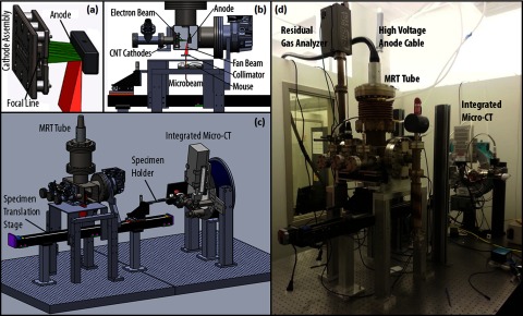
(a) Isolated view of the cathode assembly showing the five cathodes producing a focal line on the anode. (b) Side cutaway view of the MRT tube showing the electron beam from the cathodes hitting the anode and producing the fan beam which is then collimated to a microbeam. (c) 3D model of the MRT and micro-CT image guided therapy system. (d) Picture of the desktop MRT system with integrated micro-CT mounted on the optical table.
The specially designed linear CNT x-ray source array, as described in previous publications,18 consists of a linear CNT cathode which emits electrons under a bias extraction field, a gating electrode, an electrostatic focusing lens to focus the electron beam, and an opposing stationary tungsten anode. The electron beam is focused down to a narrow 0.145 × 160 mm focal track on the anode. The x-ray source array is operated at 160 kVp anode voltage and a tube current of 30 mA. The mean energy is 60 keV and the HVL was determined to be 7.5 mm Al.18 The intrinsically divergent radiation is collimated into microbeam using a motorized microbeam collimator placed between the x-ray window and the object, 65.2 mm below the focal spot on the anode. In the present system, parallel planes of microbeams are delivered by translating the object in the direction perpendicular to the microbeam plane in a step and shoot fashion. A PVDR of 16 was obtained at 4:1 pitch/width ratio and 280 mm beam width, measured 124 mm below the focal spot or 58.8 mm below the collimator. The beam spread angle was calculated to be 0.15°.20
The gate mesh, which is directly above the CNT substrates on the cathodes, is grounded, the anode is set to 160 kVp, and the cathodes are pulsed from ground to a negative voltage using a pulse generator to produce x rays at scheduled intervals. In regular experiments where gating is not used, the tube is operated at an 8% duty cycle using 500 μs width pulses. The pulse diagram for the gated system can be seen below in Fig. 4. The beam delivers an average dose rate of approximately 1.4 Gy/min at entrance. The dose is measured using EBT2 Gafchromic© dosimetry film. The dosimetry film is calibrated by comparing the average of the red, green, and blue channels of the film to ion chamber measurements.18
FIG. 4.
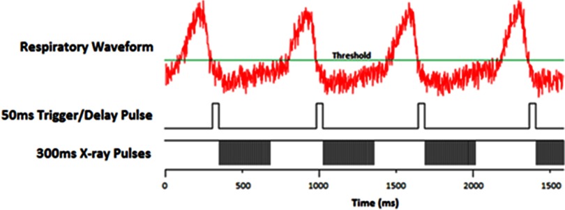
X-ray exposure pulse diagram. The top is the BioVetc output of the respiratory motion from the pressure sensor attached to the mouse. The threshold is set by the operator as low as possible but still having the “motionless” state below it. The second pulse sequence shows the delay pulses that start the irradiation on a high-to-low trigger. The last sequence shows the cathode pulses that generate the x-rays. The cathodes are negatively pulsed at 500 μs pulse widths with an 8% duty cycle.
II.B. Physiological motion monitoring
A physiological monitoring and triggering system (BioVet©, Spin Systems, South Brisbane, Australia) is used to monitor the respiratory motion. The respiration signal is obtained from a sensor pad placed on the surface of the animal under the abdomen to monitor chest cavity motion.23,24,26 The respiration sensor is a foam pad encased in a rubber shell attached to thin tubing running into the sensor processor. The signal measures the pressure change in the tubing caused by the compression of the foam.
II.C. Mechanical phantom
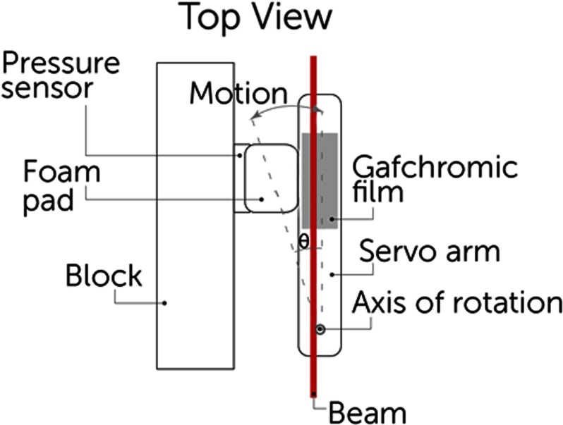
We designed a phantom to simulate mouse chest respiratory motion using a servo motor. A 50 mm long plastic arm attached to the servo was equipped with a Gafchromic film strip and set in contact with a pressure sensor. The arm was set to rotate 1° with a period of 800 ms and a 25% duty cycle, equating to a motion of about 1 mm which mimics actual mouse breathing motion of the abdomen.27 The setup is shown in Fig. 2.
FIG. 2.
Schematic of phantom using servo motor arm simulating mouse abdominal motion during breathing. The arm is always in contact with the foam pad and the pressure sensor and oscillates in the direction shown.
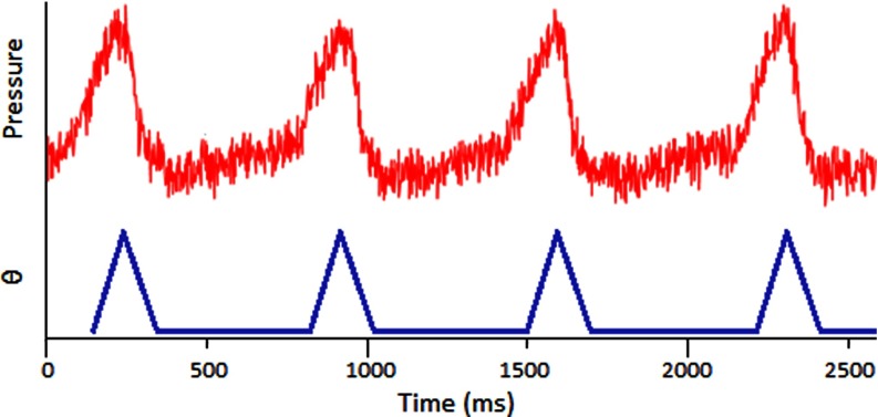
Previous gating experiments23 have shown that the respiration signal is nonsinusoidal and causes major motion 25% of the time and a relaxed period between breaths 75% of the time. A sample respiratory signal is shown in Fig. 3. The vertical axis is a differential pressure measurement which is correlated to the chest displacement. The angular displacement of the servo is shown as a function of time and closely matches an actual respiration signal.
FIG. 3.
BioVet© differential pressure measurement, correlated to chest displacement, compared to the phantom angular displacement.
II.D. Mouse model and handling
For the in vivo MRT studies, adult male athymic mice are used. The mouse is placed in a mouse holder 3D printed using fused deposition modeling. The mouse is first sedated in an induction chamber and quickly moved onto the mouse stage. The stage holds an anesthesia tube that pumps 1.5%–2% isofluorane and oxygen mixture directly to the mouse's nose. For body irradiations, the mouse is positioned on its side and taped down with medical tape to immobilize it. Experimental procedures carried out in this study were approved by the Institutional Animal Care and Use Committee at our institution.
II.E. Respiratory gated irradiation
Figure 3 shows a typical respiratory signal from anesthetized mouse. As it is shown here, there is a periodically short period of time between two inhalations where the chest is not moving as much. Using this respiratory signal, the constant radiation can be broken up into pulses to irradiate only triggered at the end of the inhalation and last during these “motionless” states. The gating program on the MRT control system runs as follows. The settings are based on individual mice and after the mouse is positioned, the operator waits for its breathing to stabilize while adjusting the anesthesia dose as necessary. During this time, the program reads in several breaths to help the operator get a general idea of the signal. A minimum threshold is set such that the “motionless” baseline is completely underneath it, shown in Fig. 4, which sets up the triggers. The operator then determines the “on” time of irradiation by setting a 10% and 20% buffer at the beginning and end of the pulses, respectively. In the sample respiratory waveform from Fig. 3, the “motionless” state is 500 ms long. This requires a 50 ms delay buffer at the beginning and a 100 ms buffer at the end, making the “on” time 350 ms. The pulse diagram is summarized in Fig. 4.
The operator then sets a minimum period allowed, generally within 10% of the current period, which shuts off the pulses if crossed and indicates that the mouse is breathing faster and waking up. Because it is normal for the mouse to involuntarily twitch at times and breathe faster for a few breaths, the program reads in and averages the last six triggers to determine whether or not to turn off the irradiation. After the mouse is stabilized, the program can be turned back on to resume the treatment.
II.F. Irradiation protocols
II.F.1. Mechanical phantom
Two types of experiments were run. The first was a single line irradiation at 160 kVp delivering 1.4 Gy/min for 5 min. The second was a three line irradiation, separated by 900 μm with the same irradiation conditions for each line. We recorded the dose profile by irradiating EBT2 Gafchromic© dosimetry film and scanning and processing the resulting lines.
II.F.2. Mouse study
We ran an in vivo gated irradiation experiment with three microbeam lines. The liver was chosen as the target organ for a proof of concept study due to its large motion during respiration compared to other organs. The liver location was confirmed through a single 2D projection x-ray using the integrated micro-CT imaging system. The beams are marked in relation to the location of the liver. Each line was separated by 900 μm center-to-center and was delivered 12.4 Gy, which was calculated to be 106 600 pulses
The first two lines were delivered without gating as a control and the third line was gated to the respiration motion. The irradiation times for each line were 11, 11, and 33 min, respectively.
II.G. Histology
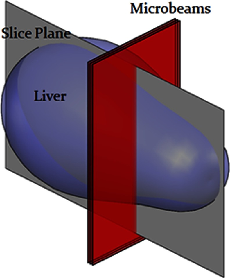
To confirm the beam placement, γ-H2AX immunofluorescence staining is used as a quantitative biomarker of radiation-induced DNA double-strand breaks.28 The mouse was euthanized 1 h after treatment and its body still in the bed was fixed in formalin for 24 h to preserve the liver orientation during transport from the radiation site to the tissue facility. The formalin allowed the body and all internal organs to remain on the mouse bed exactly how it was during irradiation. The liver was then carefully removed, noting the orientation, and the tissue was embedded in paraffin and sectioned into 5 μm slices in the plane perpendicular to and following the microbeams, shown in Fig. 5.
FIG. 5.
Diagram of histology section plane.
The staining protocol was as follows: The tissue slice was hydrated and underwent antigen retrieval process by incubated with citrate buffer. The sample was then incubated with the primary antibody (Phosphohistone H2AX Rabbit antimouse antibody, Cell Signaling Technology, Inc.) for 60 min, followed by incubation with secondary antibody with Cy5 Tyramide and DAPI counterstaining on the nuclei. The section was then scanned using a fluorescence slide scanner system (Scanscope FL scanner, Aperio, Inc., Vista, CA) to obtain γ-H2Ax stained images.
III. RESULTS
III.A. Film results from phantom study
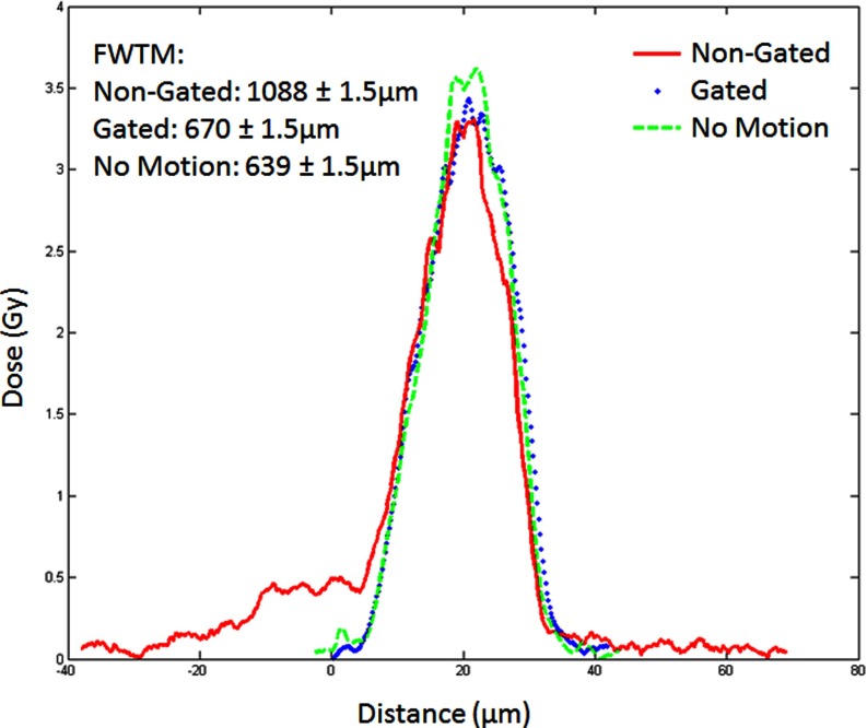
In the single beam case, the film was scanned and analyzed using Film QA Pro© from Ashland Advanced Material Group. The program determines the shape of the dose pattern along with the dose delivered. Figure 6 shows an example of dose profiles for a single microbeam in three cases: no motion, motion without gating, and motion with gating.
FIG. 6.
Single beam dose curves for three 5 min irradiations at 160 kVp.
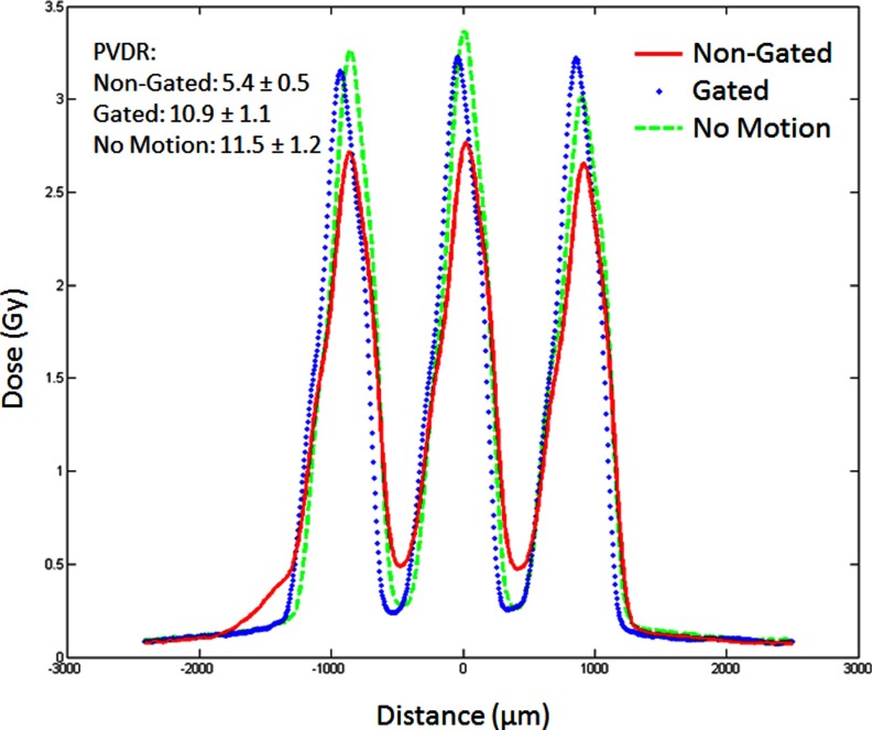
A more important quantity for the effectiveness of the MRT is the PVDR for the multiple line case. Figure 7 shows the beam profiles for three-line irradiations. Here, we see how that shelf in the single line affects the PVDR of the multiline set. The motion causes a 50% drop in PVDR from 11.5 to 5.4 but by effective gating, one can almost recover the PVDR value. There is only 5.5% decrease in PVDR in the case of motion with gating compared to the no motion case. There is also small drop in the peak dose from 3.4 to 3.2 Gy.
FIG. 7.
Three beam dose curves for three 5 min/line irradiations at 160 kVp.
III.B. Histology results from mouse study
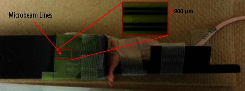
Figure 8 shows the mouse post-treatment with the beam lines shown on the Gafchromic film attached to the edge of the mouse bed.
FIG. 8.
Mouse in the mouse bed post-treatment with MRT beam lines shown on EBT2 Gafchromic© dosimetry film taped to bed.
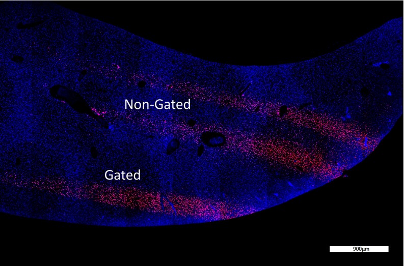
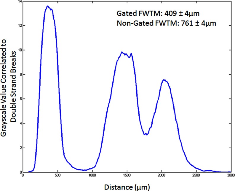
Figure 9 shows the γ-H2Ax stained liver sample that highlights double stranded breaks in the DNA from radiation damage to the tissue. The microbeams are clearly seen and their plot profiles are shown in Fig. 10. The gated PVDR increased by a factor of 2.4 as compared to the nongated lines. This is close to the 2.0 factor increase in the phantom study. The full width at tenth maximum (FWTM) decreased by 40% by gating. This is also close to the 38% decrease seen in the phantom study.
FIG. 9.
γ-H2Ax staining of a liver cross section showing gated and nongated lines. The stained points show DNA double strand breaks which is proportional to the dose delivered.
FIG. 10.
Double strand break profile of the γ-H2Ax stain in Fig. 9.
IV. DISCUSSION AND CONCLUSION
In this paper, we have shown that physiologically gated MRT is possible using our CNT based field emission microbeam irradiator. We have demonstrated that motion gating reduced valley dose and enhanced PVDR between the lines during long-time irradiation.
From the phantom study, when there is no motion, the full width at half maximum (FWHM) of the dose profile is approximately 440 μm, which is expected from geometrical consideration of the beam spread versus the height. The 280 μm beam width is obtained 1 cm below the collimator during mouse irradiations but as the phantom was much larger, it had to be placed about 13 cm below which broadened the beam to 440 μm. When the phantom motion is turned on, the broadening of the dose profile due to motion is clearly seen in the motion control as a side tail.
The FWHM of all curves is the same because the motion was not sinusoidal. Had it been, the peak would have truly “broadened” but since the motion was driven by a 25% duty cycle pulse, the movement contribution is seen as the 0.5 Gy shelf to the left. A more accurate measurement would be to look at the FWTM. FWTM increases from 638 to 1088 μm when the motion is turned on. By applying gating the FWTM is reduced back to 669 μm, almost the same as that without motion.
The irradiation time during gating notably increased from 11 to 33 min to deliver the same dose. This is because of the off-time enforced during the respiratory motion of the animal. Our tube is run at an 8% duty cycle of 500 μs pulses to prevent overheating, but during gating, the effective duty cycle was dropped to 2.7% due to the stops (). Assuming the animal's breathing remains mostly constant during the procedure, we can recover this extra treatment time simply by increasing the duty cycle of the pulses by the factor , or in our case .
We further demonstrated its therapy capability of free-breathing mice under their natural position without forced ventilation. With free-breathing, there is no need to do intubation for forced ventilation, thus reducing any damage due to the intubation procedure. Free-breathing also eliminates possible ventilation problems due to changes of tidal volume during treatment, reducing anesthesia caused mortality in forced ventilation.
The technique presented here showed a proof-of-concept method of gated radiation treatment. The liver was chosen due to its increased motion during breathing and the ease of radiation detection using γ-H2AX staining. This technique can be expanded to other areas of the body and can be gated to other physiological signals, such as the cardiac cycle.
ACKNOWLEDGMENTS
This work is supported by the National Cancer Institute (NCI) funded Carolina Center for Cancer Nanotechnology Excellence (U54-CA151652). The authors would also like to thank Jon Frank from UNC BRIC for helping with animal handling.
REFERENCES
- 1.Slatkin D., Spanne P., Dilmanian F., and Sandborg M., “Microbeam radiation therapy,” Med. Phys. 19, 1395–1400 (1992). 10.1118/1.596771 [DOI] [PubMed] [Google Scholar]
- 2.Slatkin D. N., Spanne P., Dilmanian F. A., Gebbers J. O., and Laissue J. A., “Subacute neuropathological effects of microplanar beams of x-rays from a synchrotron wiggler,” Proc. Natl. Acad. Sci. U.S.A. 92, 8783–8787 (1995). 10.1073/pnas.92.19.8783 [DOI] [PMC free article] [PubMed] [Google Scholar]
- 3.Thomlinson W., Berkvens P., Berruyer G., Bertrand B., Blattmann H., Brauer-Krisch E., Brochard T., Charvet A. M., Corde S., Dimichiel M., Elleaume H., Esteve F., Fiedler S., Laissue J. A., Le Bas J. E., Le Duc G., Lyubimova N., Nemoz C., Renier M., Slatkin D. N., Spanne P., and Suortti P., “Research at the European Synchrotron Radiation Facility medical beamline,” Cell. Mol. Biol. (Noisy-le-grand) 46, 1053–1063 (2000). [PubMed] [Google Scholar]
- 4.Laissue J. A., Lyubimova N., Wagner H., Archer D. W., Slatkin D. N., Di Michiel M., Nemoz C., Renier M., Brauer E., and Spanne P. O., “Microbeam radiation therapy,” In SPIE’s International Symposium on Optical Science, Engineering, and Instrumentation, pp. 38–45 International Society for Optics and Photonics, 1999. [Google Scholar]
- 5.Serduc R., Bouchet A., Bräuer-Krisch E., Laissue J. A., Spiga J., Sarun S., Bravin A., Fonta C., Renaud L., and Boutonnat J., “Synchrotron microbeam radiation therapy for rat brain tumor palliation—influence of the microbeam width at constant valley dose,” Phys. Med. Biol. 54, 6711–6724 (2009). 10.1088/0031-9155/54/21/017 [DOI] [PubMed] [Google Scholar]
- 6.Dilmanian F. A., Morris G. M., Zhong N., Bacarian T., Hainfeld J. F., Kalef-Ezra J., Brewington L. J., Tammam J., and Rosen E. M., “Murine EMT-6 carcinoma: High therapeutic efficacy of microbeam radiation therapy,” Radiat. Res. 159, 632–641 (2003). 10.1667/0033-7587(2003)159[0632:MECHTE]2.0.CO;2 [DOI] [PubMed] [Google Scholar]
- 7.Miura M., Blattmann H., Bräuer-Krisch E., Bravin A., Hanson A., Nawrocky M., Micca P., Slatkin D., and Laissue J., “Radiosurgical palliation of aggressive murine SCCVII squamous cell carcinomas using synchrotron-generated X-ray microbeams,” British Institute of Radiology 79, 71–75 (2006). 10.1259/bjr/50464795 [DOI] [PubMed] [Google Scholar]
- 8.Dilmanian F. A., Zhong Z., Bacarian T., Benveniste H., Romanelli P., Wang R., Welwart J., Yuasa T., Rosen E. M., and Anschel D. J., “Interlaced x-ray microplanar beams: A radiosurgery approach with clinical potential,” Proc. Natl. Acad. Sci. U.S.A. 103, 9709–9714 (2006). 10.1073/pnas.0603567103 [DOI] [PMC free article] [PubMed] [Google Scholar]
- 9.Gil S., Sarun S., Biete A., Prezado Y., and Sabes M., “Survival analysis of F98 glioma rat cells following minibeam or broad-beam synchrotron radiation therapy,” Radiat. Oncol. 6, 37 (2011). 10.1186/1748-717X-6-37 [DOI] [PMC free article] [PubMed] [Google Scholar]
- 10.Prezado Y., Sarun S., Gil S., Deman P., Bouchet A., and Le Duc G., “Increase of lifespan for glioma-bearing rats by using minibeam radiation therapy,” J. Synchrotron Radiat. 19, 60–65 (2011). 10.1107/S0909049511047042 [DOI] [PubMed] [Google Scholar]
- 11.Bouchet A., Lemasson B., Le Duc G., Maisin C., Bräuer-Krisch E., Siegbahn E. A., Renaud L., Khalil E., Rémy C., and Poillot C., “Preferential effect of synchrotron microbeam radiation therapy on intracerebral 9L gliosarcoma vascular networks,” Int. J. Radiat. Oncol., Biol., Phys. 78, 1503–1512 (2010). 10.1016/j.ijrobp.2010.06.021 [DOI] [PubMed] [Google Scholar]
- 12.Dilmanian F., Qu Y., Liu S., Cool C., Gilbert J., Hainfeld J., Kruse C., Laterra J., Lenihan D., and Nawrocky M., “X-ray microbeams: Tumor therapy and central nervous system research,” Nucl. Instrum. Methods Phys. Res. A 548, 30–37 (2005). 10.1016/j.nima.2005.03.062 [DOI] [PMC free article] [PubMed] [Google Scholar]
- 13.Zeman W., Curtis H., and Baker C., “Histopathologic effect of high-energy-particle microbeams on the visual cortex of the mouse brain,” Radiat. Res. 15, 496–514 (1961). 10.2307/3571293 [DOI] [PubMed] [Google Scholar]
- 14.Renier M., Brochard T., Nemoz C., Requardt H., Bräuer E., Esteve F., Balosso J., Suortti P., Baruchel J., and Elleaume H., “The radiotherapy clinical trials projects at the ESRF: Technical aspects,” Eur. J. Radiol. 68, S147–S150 (2008). 10.1016/j.ejrad.2008.04.057 [DOI] [PubMed] [Google Scholar]
- 15.Ohno Y., Torikoshi M., Suzuki M., Umetani K., Imai Y., Uesugi K., and Yagi N., “Dose distribution of a 125 keV mean energy microplanar x-ray beam for basic studies on microbeam radiotherapy,” Med. Phys. 35, 3252–3258 (2008). 10.1118/1.2940157 [DOI] [PubMed] [Google Scholar]
- 16.Cheng Y. and Zhou O., “Electron field emission from carbon nanotubes,” C. R. Phys. 4, 1021–1033 (2003). 10.1016/S1631-0705(03)00103-8 [DOI] [Google Scholar]
- 17.Zhang J., Yang G., Cheng Y., Gao B., Qiu Q., Lee Y., Lu J., and Zhou O., “Stationary scanning x-ray source based on carbon nanotube field emitters,” Appl. Phys. Lett. 86, 184104 (2005). 10.1063/1.1923750 [DOI] [Google Scholar]
- 18.Hadsell M., Zhang J., Laganis P., Sprenger F., Shan J., Zhang L., Burk L., Yuan H., Chang S., and Lu J., “A first generation compact microbeam radiation therapy system based on carbon nanotube X-ray technology,” Appl. Phys. Lett. 103, 183505 (2013). 10.1063/1.4826587 [DOI] [PMC free article] [PubMed] [Google Scholar]
- 19.Zhou O. Z. and Chang S. X., “Compact microbeam radiation therapy systems and methods for cancer treatment and research,” U.S. patent application 12/688,425 (Jan 15, 2010).
- 20.Zhang L., Yuan H., Burk L. M., Inscoe C. R., Hadsell M. J., Chtcheprov P., Lee Y. Z., Lu J., Chang S., and Zhou O., “Image-guided microbeam irradiation to brain tumour bearing mice using a carbon nanotube x-ray source array,” Phys. Med. Biol. 59, 1283–1303 (2014). 10.1088/0031-9155/59/5/1283 [DOI] [PMC free article] [PubMed] [Google Scholar]
- 21.Zhong X., Meyer C. H., Schlesinger D. J., Sheehan J. P., Epstein F. H., Larner J. M., Benedict S. H., Read P. W., Sheng K., and Cai J., “Tracking brain motion during the cardiac cycle using spiral cine-DENSE MRI,” Med. Phys. 36, 3413–3419 (2009). 10.1118/1.3157109 [DOI] [PMC free article] [PubMed] [Google Scholar]
- 22.Zhang J., Cheng Y., Lee Y., Gao B., Qiu Q., Lin W., Lalush D., Lu J., and Zhou O., “A nanotube-based field emission x-ray source for microcomputed tomography,” Rev. Sci. Instrum. 76, 094301 (2005). 10.1063/1.2041589 [DOI] [Google Scholar]
- 23.Cao G., Burk L. M., Lee Y. Z., Calderon-Colon X., Sultana S., Lu J., and Zhou O., “Prospective-gated cardiac micro-CT imaging of free-breathing mice using carbon nanotube field emission x-ray,” Med. Phys. 37, 5306–5312 (2010). 10.1118/1.3491806 [DOI] [PMC free article] [PubMed] [Google Scholar]
- 24.Lee Y. Z., Burk L. M., Wang K., Cao G., Volmer J., Lu J., and Zhou O., “Prospective respiratory gated carbon nanotube micro computed tomography,” Acad. Radiol. 18, 588–593 (2011). 10.1016/j.acra.2010.11.022 [DOI] [PMC free article] [PubMed] [Google Scholar]
- 25.Lee Y. Z., Burk L., Wang K., Cao G., Lu J., and Zhou O., “Carbon nanotube based X-ray sources: Applications in pre-clinical and medical imaging,” Nucl. Instrum. Methods Phys. Res. A 648, S281–S283 (2011). 10.1016/j.nima.2010.11.053 [DOI] [PMC free article] [PubMed] [Google Scholar]
- 26.Cao G., Lee Y., Peng R., Liu Z., Rajaram R., Calderon-Colon X., An L., Wang P., Phan T., and Sultana S., “A dynamic micro-CT scanner based on a carbon nanotube field emission x-ray source,” Phys. Med. Biol. 54, 2323–2340 (2009). 10.1088/0031-9155/54/8/005 [DOI] [PubMed] [Google Scholar]
- 27.Yang Y., Rendig S., Siegel S., Newport D. F., and Cherry S. R., “Cardiac PET imaging in mice with simultaneous cardiac and respiratory gating,” Phys. Med. Biol. 50, 2979–2989 (2005). 10.1088/0031-9155/50/13/001 [DOI] [PubMed] [Google Scholar]
- 28.Kuo L. J. and Yang L. X., “Gamma-H2AX: A novel biomarker for DNA double-strand breaks,” In Vivo 22, 305–309 (2008). [PubMed] [Google Scholar]


