Abstract
We are developing a cardiac pacemaker that is designed to be implanted percutaneously into a fetus to treat complete heart block and consequent hydrops fetalis, which is otherwise fatal. One of the most significant considerations for this device is the technical challenges presented by the battery and charging system. The size of the device is limited to about 3 mm in diameter; batteries on this scale have very small charge capacities. The smaller capacity means that the device needs to be designed so that it uses as little current as possible and so that its battery can be recharged wirelessly. We determined the pacing thresholds for a simple relaxation oscillator that can be assembled from discrete, surface mount components and analyzed the power consumption of the device given different electrode configurations and stimulus parameters. An inductive recharging system will be required for some patients; it is feasible within the package constraints and under development.
I. INTRODUCTION
Complete heart block in the fetus is a life-threatening emergency with no effective treatment options beyond watchful waiting [1, 2]. Fetal bradycardia due to heart block can progress in utero, and for more than a quarter of these fetuses may result in hydrops fetalis [3, 4]. Once hydrops fetalis develops, if the fetus cannot be delivered due to prematurity or other clinical concerns, fetal demise is nearly inevitable [2]. Pharmacological and immunological therapies delivered systemically via the mother have not been effective in clinical trials [5-7].
When a newborn, child or adult presents with symptomatic complete heart block, treatment usually consists of implantation of a pacemaker to ensure an adequate heart rate. With appropriate pacing, these patients are usually asymptomatic with an excellent prognosis. Similar benefits would be expected from pacing a fetus with complete heart block, theoretically allowing resolution of hydrops in 1-2 weeks and permitting an otherwise normal gestation. A conventional pacemaker would then be implanted at delivery. Over the last two decades, several investigators have attempted to place pacemakers in a fetus [8-10]. To date, however, there have been no survivors of fetal pacing. Previous approaches have relied on the placement of a pacing wire on the fetal heart with an extra-uterine pulse generator implanted in the mother. This has inevitably failed because of lead dislodgement due to fetal movement.
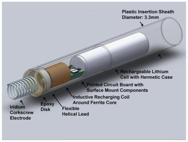
We have designed a single-chamber pacing system that is self-contained and can be completely implanted in the fetus without leads, thereby permitting subsequent fetal movement without risk of dislodgement of the electrodes (Fig. 1) [11]. Such a design is now possible because of significant developments in medical device miniaturization and advances in fetal surgical intervention, allowing the pacing system to be percutaneously deployed through the maternal abdomen under ultrasound guidance.
Figure 1.
Solidworks model of the rechargeable micropacemaker within plastic insertion sheath. The corkscrew electrode at the left is made from pure iridium that has been activated to achieve a low interface impedance with tissue by growing a layer of iridium oxide on its surface. For details, see Zhou et al., this conference [11].
II. DEVICE DESIGN
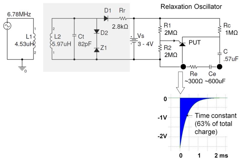
The fetal pacemaker is designed to be a simple, compact, low-power device that generates brief electrical stimuli that initiate ventricular contractions at a physiological rate. Relaxation oscillators have high reliability and draw little power while they are operating, making them well suited for this application. The relaxation oscillator for this device uses a programmable unijunction transistor (PUT, Fig. 2), paired with a capacitor and a battery. The battery charges the capacitor while the PUT remains off. Once the capacitor exceeds a gate voltage on the PUT, the PUT turns on and creates a current path that discharges the capacitor through the heart tissue. Once the current in that path drops to a certain level, the PUT reverts back to a high resistance state and the capacitor can begin charging again. The gate voltage for the PUT is set by biasing resistors R1 & R2. The stimulus charge depends on the product of capacitor C and the gate voltage. The stimulus rate depends on the time constant of capacitor C and charging resistor Rc. All of these component values must be optimized to achieve the desired combination of reliable pacing and long battery life. Once it is finalized, the system can be built on a printed circuit with surface-mounted components, making the profile as slim as possible.
Figure 2.
Schematic diagram of relaxation oscillator (right top) with typical output pulse (insert below), with optional recharging circuitry (light grey box at left) for inductive recharging from external coil L1, including tuning capacitor Ct, voltage limiting zener diode Z1 and charge current limiting resistor Rr. Insert below shows typical exponential cathodal pulse from corkscrew Ir electrode (open arrow) with typical values for Ce after activation and Re in myocardium.
The battery to be used (actually a single, rechargeable lithium cell) was chosen for its size, about 3mm in diameter, and its hermetic packaging. It is manufactured by Quallion and has a nominal capacity of 3mAh. The mean discharge rate and operating temperature for this application are well within normal operating range for this cell, so it is expected that it will perform according to the nominal specifications from the manufacturer.
III. METHODS
To understand better the pacing threshold of a fetal heart, we paced three anesthetized adult rabbits whose beating hearts were exposed via thoracotomy and then sacrificed with a barbiturate overdose. The electrodes were screwed into the myocardium at various locations while monitoring the surface ECG. Pacing threshold was measured over varying pulse durations to produce a strength-duration curve for one electrode placement in one rabbit. Pacing threshold was defined as the minimal value that produced ventricular myocardial capture (demonstrated by the presence of premature ventricular contractions on the ECG). Stimulation pulses were generated by a conventional clinical analyzer for pacemaker leads (Merlin Interrogator from St. Jude Medical, Sylmar, CA) that allowed independent control of square wave voltage and duration to determine threshold for capture. The stimulus charge was estimated from the measured electrode impedance (charge = duration × voltage/impedance). We also used a custom-built instrument that contained the PUT and associated circuitry for our fetal micropacemaker but with the ability to systematically vary C, Rc and Vs to determine thresholds for its exponential output pulse.
After animal studies were completed, a power budget was developed with the goal of minimizing the amount of energy being used by the system for any purpose other than directly stimulating the heart. The budget was compared to previous benchtop tests of battery lifetime to verify the device was acting predictably.
The analysis of battery life was performed by summing the average amount of current (Coulombs per second) through each pathway from the battery to the tissue or ground. There are three paths for current to flow. First, there are the passive elements of the relaxation oscillator, the gate voltage divider of R1 and R2. The current through this part of the pacemaker is constant and does not contribute to the output stimuli. The second path is through Rc and C during the charging phase, the current of which was found by taking the time average of the amount of charge over each cycle. Lastly, the current through Rc during the discharge phase when the PUT grounds this resistor was found and averaged over the time when the PUT is closed.
Battery voltage was set to 3.6V (it will actually vary between 4.0 and 3.0 depending on charging status) and pulse rate set to 130 beats per minute. All other parameters were varied.
IV. TEST RESULTS
A. Pacing Threshold Measurement
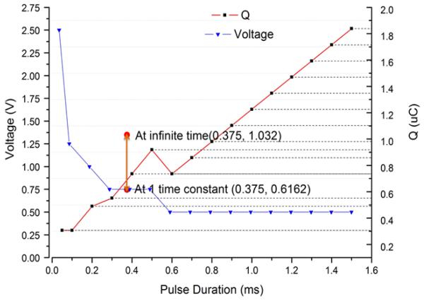
The strength-duration curve for one insertion of a 1.2mm diameter corkscrew electrode into rabbit myocardium and stimulating with a conventional square-pulse generator (Merlin Interrogator) is plotted in Figure 3. The relaxation oscillator produces an exponentially declining stimulus (insert in Figure 2) that does not provide explicit control of current or duration but does provide precise control of the pacing charge (and hence power consumption) by varying capacitor C. Therefore, threshold charge in the animal could only be measured with one pulse duration with the relaxation oscillator (Figure 3, orange dots). Importantly, the charge required to pace was comparable to that of the square wave; see bracketed red line in Figure 3 for one placement of a 1.2mm coil electrode. The chronaxie for a conventional square-wave stimulus is approximately 0.5ms and its threshold charge lies between the total charge of the exponential pulse at infinity and the charge delivered at one time constant (τ=0.375ms). Note that only relatively coarse steps (factors of 2) were used for C, corresponding to the limited range of medical grade capacitors available in the 0402 surface mount package required for the implant.
Figure 3.
Measured pacing threshold voltage (blue line; left ordinate) and threshold charge (red line; right ordinate) vs. pulse duration determined experimentally in a rabbit using a square stimulus at the Left Ventricular Apex. Threshold charge was also measured for exponential pulses delivered at the Left Ventricular Apex from the designed relaxation oscillator (vertical bar at time constant = 0.375ms).
B. Power Budget
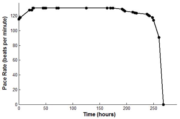
Trial 1 was modeled after a test performed on battery life on the benchtop. The mean current delivered by the pulsing system is about 10μC/second. The charge of one pulse is about 4.7μC. The pulse rate is about 130 beats per minute; the pulse duration, from the peak of the pulse to 33% of the peak, is 0.6msec. These parameters with a 3mAh capacity battery predict that the battery will last 9 days (Table 1). A physical trial of the battery life was done with identical parameters. The battery voltage varies from approximately 3.0 to 4.0V depending on the state of charge, which causes a small but readily detectable change in the output pulse rate when the device is nearing full discharge (Fig. 4). The pacemaker was fully charged and then allowed to completely discharge while rate was observed, and showed a lifetime of about 10 days.
TABLE I.
POWER BUDGET OVER DIFFERENT CONDITIONS
| Charge delivered over time (C/s = A) | |||
|---|---|---|---|
|
|
|||
|
Trial 1:
Benchtop test configuration |
Trial 2: Higher
resistance through passive element |
Trial 3:
Variability among PUTs |
|
| R1 and R2 | 2.81μA | 0.9μA | 5.19μA |
| Exponential decay pulse |
10.1μA | 1.58μA | 2.22μA |
| Rc | 0.026μA | 0.002μA | 0.003μA |
| Total Discharge Current |
12.9μA | 2.48μA | 7.41μA |
| Days | 9.66 days | 50.4 days | 16.9 days |
Figure 4.
Stimulus rate (beats per minute) vs. hours of continuous pacing output for a high output design (6.38μC @ 2.9Vcompliance, 130bpm at full charge). The initial rate increase is a conditioning effect in the UJTwhen its threshold is set near Vs; it does not recur when recharged during continuous output.
Animal tests demonstrated that much smaller charge pulses than those used during initial development could usually stimulate the heart. As we reduce the amount of current drawn by the active pacing part of the device, the current drawn by the passive part of the device starts to have more influence on the battery life. The actual values of R1 & R2 are limited by instability in the PUT that occurs when the threshold is near the available power supply voltage, so reducing the stimulus charge by reducing the voltage excursion on C (which is equal to the threshold voltage on the PUT) provides an opportunity to reduce passive power consumption disproportionately. The animal tests suggested that a pulse of 0.73μC would provide an adequate safety margin to assure reliable pacing for most electrode placements in the ventricular myocardium. Trial 2 of the power budget shows that raising values for R1 and R2 has a dramatic effect on the predicted battery lifetime, in addition to the smaller charge required for the actual stimulus pulses. With these changes, the predicted lifetime of the device is 50 days, which would mean some patients will not require recharging.
One limitation to raising the values for R1 and R2 is that there was considerable variability among samples of the programmable unijunction transistors. Therefore, the next budget (Trial 3) was calculated to achieve an average lifetime given variability in PUTs. In order to keep the same gate voltage for the three tested PUTs, lower values for R1 were used, yielding a higher gate voltage (1.80V instead of 1.28V) for this trial. The average PUT would give a substantial reduction in battery life. When we triple the discharge current in Trial 3, we get a third of the battery life as compared to Trial 2. This shows that the values for the resistors R1 and R2 still have a significant effect on the power consumption, and steps should be taken to find PUTs that are less variable with more optimal characteristics.
V. DISCUSSION
The data from the animal experiments and bench-testing of the component values will be combined into a final design for fabrication and testing. The capacitor and the gate voltage dictate how much charge is delivered to the tissue for each pulse. The thresholds that we obtained in the adult rabbit hearts were similar to those obtained in a hydropic human fetus before the lead was dislodged [9]. We are aiming for a charge of about two times the average threshold. Such a safety factor is necessary because the stimulus parameters cannot be adjusted after implantation. Fortunately, pacing capture can be confirmed while the pacemaker is still attached to its insertion sheath, permitting the electrode to be relocated in the myocardium if necessary before release of the device into the chest of the fetus.
We estimate that the final design will require a mean battery current of about 4μA, so the 3mAh lithium cell should last about 31 days on a single charge. The cell can be kept charged until the time of implantation by applying a recharging current through an inductive recharging circuit, as shown schematically in Figure 1. Fetuses that develop hydrops early or cannot be delivered prematurely will require more than 3 to 4 weeks of pacing, and the inductive link will serve to recharge the device transcutaneously. Future work will involve designing a primary coil and class E RF oscillator for transcutaneous charging.
ACKNOWLEDGMENTS
This research was funded by the Southern California Clinical and Translational Science Institute and by the Robert E. and May R. Wright Foundation. The authors thank consultant Glen Griffith for feasibility analysis of the inductive recharging scheme.
Contributor Information
Adriana Nicholson, Medical Device Development Facility, Department of Biomedical Engineering, Viterbi School of Engineering, University of Southern California, Los Angeles, CA 90089.
Ramen Chmait, Maternal Fetal Medicine in the Keck School of Medicine, University of Southern California, Los Angeles, CA, 90089 USA.
Yaniv Bar-Cohen, Pediatric Cardiology at Children’s Hospital Los Angeles, Los Angeles, CA, 90027 USA.
Kaihui Zheng, Medical Device Development Facility, Department of Biomedical Engineering, Viterbi School of Engineering, University of Southern California, Los Angeles, CA 90089.
Gerald E. Loeb, Medical Device Development Facility, Department of Biomedical Engineering, Viterbi School of Engineering, University of Southern California, Los Angeles, CA 90089.
REFERENCES
- [1].Groves AM, Allan LD, Rosenthal E. Outcome of isolated congenital complete heart block diagnosed in utero. Heart. 1996;75:190–194. doi: 10.1136/hrt.75.2.190. [DOI] [PMC free article] [PubMed] [Google Scholar]
- [2].Schmidt KG, Ulmer HE, Silverman NH, Kleinman CS, Copel JA. Perinatal outcome of fetal complete atrioventricular block: A multicenter experience. Journal of the American College of Cardiology. 1991;17:1360–1366. doi: 10.1016/s0735-1097(10)80148-2. [DOI] [PubMed] [Google Scholar]
- [3].Friedman DM, Kim MY, Copel JA, Davis C, Phoon CKL, Glickstein JS, Buyon JP, f. t. P. Investigators Utility of Cardiac Monitoring in Fetuses at Risk for Congenital Heart Block. Circulation. 2008;117:485–493. doi: 10.1161/CIRCULATIONAHA.107.707661. [DOI] [PubMed] [Google Scholar]
- [4].Groves AM, Allan LD, Rosenthal E. Therapeutic Trial of Sympathomimetics in Three Cases of Complete Heart Block in the Fetus. Circulation. 1995;92:3394–3396. doi: 10.1161/01.cir.92.12.3394. [DOI] [PubMed] [Google Scholar]
- [5].Friedman DM, Llanos C, Izmirly PM, Brock B, Byron J, Copel J, Cummiskey K, Dooley MA, Foley J, Graves C, Hendershott C, Kates R, Komissarova EV, Miller M, Paré E, Phoon CKL, Prosen T, Reisner D, Ruderman E, Samuels P, Yu JK, Kim MY, Buyon JP. Evaluation of fetuses in a study of intravenous immunoglobulin as preventive therapy for congenital heart block: Results of a multicenter, prospective, open-label clinical trial. Arthritis & Rheumatism. 2010;62:1138–1146. doi: 10.1002/art.27308. [DOI] [PMC free article] [PubMed] [Google Scholar]
- [6].Pisoni CN, Brucato A, Ruffatti A, Espinosa G, Cervera R, Belmonte-Serrano M, Sánchez-Román J, García-Hernández FG, Tincani A, Bertero MT, Doria A, Hughes GRV, Khamashta MA. Failure of intravenous immunoglobulin to prevent congenital heart block: Findings of a multicenter, prospective, observational study. Arthritis & Rheumatism. 2010;62:1147–1152. doi: 10.1002/art.27350. [DOI] [PubMed] [Google Scholar]
- [7].Robinson BV, Ettedgui JA, Sherman FS. Use of terbutaline in the treatment of complete heart block in the fetus. Cardiol Young. 2001;11:683–686. doi: 10.1017/s1047951101001123. [DOI] [PubMed] [Google Scholar]
- [8].Walkinshaw SA, Welch CR, McCormack J, Walsh K. In utero Pacing for Fetal Congenital Heart Block. Fetal Diagnosis and Therapy. 1994;9:183–185. doi: 10.1159/000263929. [DOI] [PubMed] [Google Scholar]
- [9].Assad RS, Zielinsky P, Kalil R, Lima G, Aramayo A, Santos A, Costa R, Marcial MB, Oliveira SA. New lead for in utero pacing for fetal congenital heart block. The Journal of Thoracic and Cardiovascular Surgery. 2003;126:300–302. doi: 10.1016/s0022-5223(03)00220-4. [DOI] [PubMed] [Google Scholar]
- [10].Carpenter RJ, Jr, Strasburger JF, Garson A, Jr, Smith RT, Deter RL, Tristan Engelhardt H., Jr Fetal ventricular pacing for hydrops secondary to complete atrioventricular block. Journal of the American College of Cardiology. 1986;8:1434–1436. doi: 10.1016/s0735-1097(86)80319-9. [DOI] [PubMed] [Google Scholar]
- [11].Zhou L, Chmait R, Bar-Cohen Y, Peck R, Loeb GE. Percutaneously Injectable Fetal Pacemaker: Electrodes, Mechanical Design and Implantation. doi: 10.1109/EMBC.2012.6347507. to be published at this conference. [DOI] [PMC free article] [PubMed] [Google Scholar]


