Abstract
Hemofiltration (HF) is used extensively for continuous renal replacement therapy, but long-term treatment is limited by thrombosis leading to fiber clogging. Maximum filter life is typically less than 20 hours. We have achieved for the first time continuous and consistent hemofiltration for more than 100 hours using outside-in hemofiltration with the blood flow into the inter-fiber space (IFS). Although thrombi do deposit in the IFS, they have minimal affect on the blood flow and filtrate flux due to the three-dimensional system of interconnected hydrodynamic flow channels in the IFS. Microscopic examination of sections of the fiber bundle showed that deposited thrombi have dimensions about the size of the gaps between the hollow fibers and remain isolated from each other. A simple mathematical model is developed to describe the effect of thrombus deposition on the fluid flow that accounts for the enhanced performance arising from the interconnected flow. The hydrodynamic advantage of outside-in HF decreases at low anticoagulant concentration due to the instability in the blood and the very high volume fraction of thrombi that deposit in the entrance zone of the filter. These results clearly demonstrate the significant potential advantages of using outside-in hemofiltration for long-term renal replacement therapy.
Keywords: Hemofiltration, Thrombosis, Outside-In Filtration, Clogging, Filter Life
1. Introduction
Hollow fiber membranes are employed in numerous applications due to their high membrane packing density (membrane area per unit device volume) and low manufacturing costs. However, fiber clogging can be a major limitation in some systems. The impact of fiber clogging becomes particularly significant when the feed contains a high volume fraction of dispersed particles that can aggregate and adhere to the lumen of the hollow fibers.
Fiber clogging is a particular issue in blood hemofiltration used for removal of fluid and uremic toxins in renal replacement therapy [1]. The pores of hemofiltration membranes have to be sufficiently small to prevent protein loss from blood plasma, while the surface properties of the fiber lumens need to provide high membrane hemocompatibility and minimal thrombosis. However, despite significant advances in membrane materials development, fiber clogging due to thrombus deposition in the fiber lumens currently limits the maximum filter life to 15 – 40 hrs in applications of both Continuous Renal Replacement Therapy (CRRT) [2] and hemodialysis [3]. The development of wearable ultrafiltration devices that can effectively prevent hypervolemia in congestive heart failure patients is currently limited by the lack of reliable long-term hemofiltration without filter clogging.
One approach that has been used to minimize fiber clogging in many industrial applications is to use “outside-in filtration”. In this case, the feed flows into the inter-fiber space (IFS) of the fiber bundle while permeate is removed through the fiber lumens. Outside-in filtration has been an enabling technology in immersed (or submerged) membrane bioreactors and removal of particulates in water purification, allowing activated sludge with high particulate loadings to be processed for extended periods of time [4–5]. However, these systems use suspended hollow fibers that are free to move, with the fiber surface kept clean (at least in part) by aeration of the fluid in the bioreactor.
The objective of this study was to examine the potential of using outside-in filtration for long-term hemofiltration. The outside-in configuration has been used previously in membrane oxygenators, although in this case the primary motivation was the improved mass transfer characteristics with blood flow outside of the fibers [6]. Limited previous work has shown that this configuration may be attractive in blood microfiltration using hydrophobic membranes (plasmapheresis) [7], but we are unaware of any previous work on outside-in hemofiltration. Initial work was focused on developing a simple mathematical model to describe the effects of thrombus deposition on fluid flow in conventional versus outside-in hemofiltration. Experimental studies were performed to demonstrate for the first time successful blood processing in hemofiltration for >100 hours using the outside-in mode of operation. These results have important implications for the development of improved hemofiltration processes capable of providing long-term renal replacement therapy and in the treatment of hypervolemia in congestive heart failure patients.
2. Model Development
A. Simplified model for outside-in hemofiltration
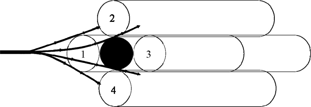
The key advantage of the outside-in configuration is the 3-dimensional and highly interconnected flow path in the inter-fiber space (IFS). Thrombus deposition in intraluminal conventional hemofiltration typically occurs at or near the entrance of an individual hollow fiber, completely blocking the entire length of that fiber leading to a significant increase in the axial pressure drop for flow through the module. Thus, in principle, the deposition of N thrombi (where N is the number of hollow fiber membranes in the module) would lead to complete blockage of the module. In contrast, thrombus deposition in the inter-fiber space will have little effect on the axial pressure drop since the blood flow is able to pass around the blockage as shown schematically in Figure 1. Deposition of the same N thrombi would occupy only a very small volume fraction of the inter-fiber space, providing minimal disturbance to the blood flow.
Figure 1.
Illustration showing flow distribution around a single thrombus (clot) in the inter-fiber space.
The effect of “interc onnectivity” on flow has been examined previously in both depth filters [8–10] and membranes [11–12]. Ho and Zydney [11] evaluated the flow distribution around a blockage on the upper surface of a symmetric membrane as a function of the pore interconnectivity, defined as the ratio of the Darcy permeability in the normal and transverse flow directions. Surface blockage on membranes with highly interconnected pores had minimal effect on the total hydraulic resistance to flow (until the upper surface is nearly totally blocked) since the fluid is able to flow around and under the surface blockage as it percolates through the porous structure of the membrane. The same phenomenon occurs in depth filters, with particle blockage occurring throughout the filter but causing relatively little change in the total resistance until the pore space within the filter is very highly plugged [8–10]
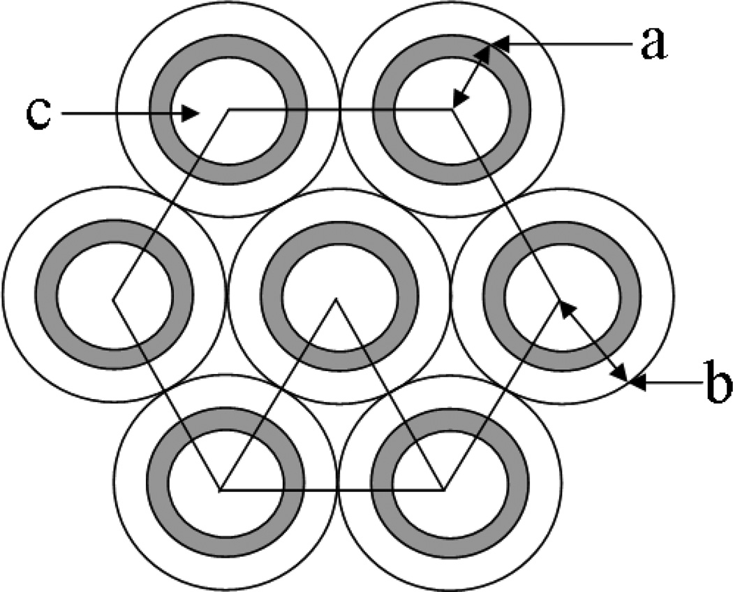
In order to obtain additional insights into the effects of thrombus deposition on the fluid flow behavior in conventional and outside-in hemofiltration, a simple mathematical model was developed to describe the axial pressure drop due to flow in the inter-fiber space. We assume that thrombi are mono-disperse with diameter (d) approximately equal to the inter-fiber spacing [Figure 2]. Two limiting cases are examined: (a) uniform distribution of thrombi within the inter-fiber space, i.e., the number of thrombi in any cross-section of the fiber bundle is constant, and (b) preferential clotting near the entrance region of the module.
Figure 2.
Schematic illustration of a hexagonal array of hollow fibers. a) external radius of fiber, b) cell radius around each fiber, c) fiber lumen.
As discussed by Herzig et al. [8], the pressure drop in a partially clogged bed can be approximated as:
| (1) |
where ΔPo and εo are the axial pressure drop and porosity of the initial (unclogged) IFS, and ε is the porosity of the partially clogged IFS. For a uniform hexagonal array of hollow fibers [Figure 2], the initial porosity is given as:
| (2) |
where a is the outer radius of the hollow fiber membrane and b is the radius of the cylinder defined by the mid-point between adjacent fibers. Equation (2) neglects the “triangular” gap between the fibers. The porosity of the partially clogged IFS is evaluated by simple geometric considerations as:
| (3) |
where n is the number of deposited thrombi, N is the number of hollow fibers, L is the fiber length, and d is the diameter of a thrombus, assumed to be equal to the interfiber spacing, i.e., d = 2(b − a). A typical hollow fiber hemofilter (see Table 1) has d = 200 µm and L = 20 cm, which corresponds to ε = 0.9993εo and ΔP = 1.002ΔPo when n = N. It would take n = 1500 N for the porosity of the inter-fiber space to drop to zero (at which point the axial pressure drop would become infinite).
Table 1.
Dialyzers/filters used with key geometric characteristics.
| Surface Area (m2) |
Fiber ID (µm) |
Fiber Length (cm) |
||
|---|---|---|---|---|
| Gambro H6 | High Flux | 0.6 | 200 | 10 |
| Sorin DHF0.2 | High Flux | 0.25 | 200 | 14.5 |
| Fresenius F3 | Low Flux | 0.4 | 200 | 20 |
| Minntech HF 400 | High Flux | 0.3 | 200 | 12 |
| Spectrum P-D1-030E-100-01N | High Flux | 0.0115 | 500 | 20 |
| Asahi Rexeed 15R | High Flux | 1.5 | 185 | 33.4 |
| Asahi Rexeed 15LX | Low Flux | 1.5 | 185 | 33.4 |
| Minntech Renaflo Mini | High Flux | 0.05 | 620 | 15 |
If all of the thrombi deposit in the entrance region of the hollow fiber module (Lent), the porosity in this region will be given by Eq. (3) but with L = Lent. In this case, the total axial pressure drop is given by the sum of the pressure drop across the entrance length (clogged) and the remainder of the fiber (unclogged):
| (4) |
If Lent = 1 cm, then ΔP is again equal to 1.002ΔPo when n = N due to the highly interconnected nature of the flow. However, under these conditions, the pressure drop would become infinite when n = 75N, leading to a 20-fold reduction in the number of thrombi that can be accommodated within the inter-fiber space.
B. Analysis of flow in outside-in hollow fiber module
As discussed by Fraser et al. [13], thrombus formation is governed by the nature of the surface, the condition of the blood (e.g., the extent of anticoagulation), and the local flow conditions. The presence of low shear (less than 250 sec−1) or stagnant flow tends to increase thrombogenicity [13]. In addition, high shear rates can activate platelets leading to thrombosis; the use of intermediate shear rates is generally considered to provide minimal thrombosis and clogging. The wall shear in conventional hemofiltration can be calculated using the Hagen-Poiseuille equation:
| (5) |
where R is the inner fiber radius, μ is the blood viscosity, and dp/dz is the axial pressure gradient in the hollow fiber.
The axial velocity in the IFS can be evaluated assuming a hexagonal array of hollow fibers (Figure 2), neglecting the “triangular” gaps between fibers, as discussed by Happel and Brenner [14]:
| (6) |
where r is the radial coordinate and a and b are the inner and outer radii of the cylinders that define the inter-fiber space. The wall shear rate on the external surface of a hollow fiber is thus:
| (7) |
Equation (7) provides a means for estimating the magnitude of the wall shear rate in the interfiber space, which is important for identifying conditions likely to cause thrombosis. For the Asahi Rexeed® dialyzers used in the subsequent experiments, a = 120 µm and ε = 0.62. Blood flow in this unit with μ = 3.5 cP gives dp/dz ≈ ΔP/L with ΔP = 40 mm Hg and L = 33.4 cm. This yields a wall shear rate of γw = 450 s−1, which is consistent with the recommended shear rates for minimal thrombosis.
The volumetric flow rate in the inter-fiber space can be evaluated by integration:
| (8) |
where Nf is the number of hollow fibers. Thus, a pressure drop of 40 mm Hg in the Asahi Rexeed® dialyzer (Nf = 7700) would yield a blood flow rate of 370 mL/min, which is about twice that observed experimentally. This discrepancy likely reflects the more complex, non-uniform, flow distribution in the inter-fiber space between the randomly arrayed hollow fibers.
3. Materials and Methods
Hemofiltration experiments were performed using a modified version of the hemodialysis system described by Morti and Zydney [15]. Blood was pumped into the hollow fiber module through the lumen feed port (conventional operation) or through the port in the inter-fiber space (outside-in configuration) using a peristaltic pump (Cole Parmer, Model No. 77200-62). The ultrafiltration rate was set at a predetermined rate using an ultrafiltrate metering pump (Fluid Metering, Inc. Model No. QV1 with V200 Controller). Digital pressure gauges (Cecomp Electronics, Inc., U.S.A.) were used to continuously record the pressure at the module inlet and outlet. The system was operated with total recycle, with the ultrafiltrate returned directly to the blood reservoir, using a constant temperature of 37°C, maintained by placing the blood reservoir on a hot plate (VWR Model No. 12365-382).
Solute clearance was evaluated using NaCl and vitamin B12 following the procedures described by Mort and Zydney [15]. NaCl concentrations in the “blood reservoir” were measured using a conductivity meter (Myron L. Company, Ultrameter) with vitamin B12 evaluated spectrophotometrically using the absorbance at 360 nm (Beckman, DU® 530). Data were obtained in dialysis mode using the solutes dissolved in saline.
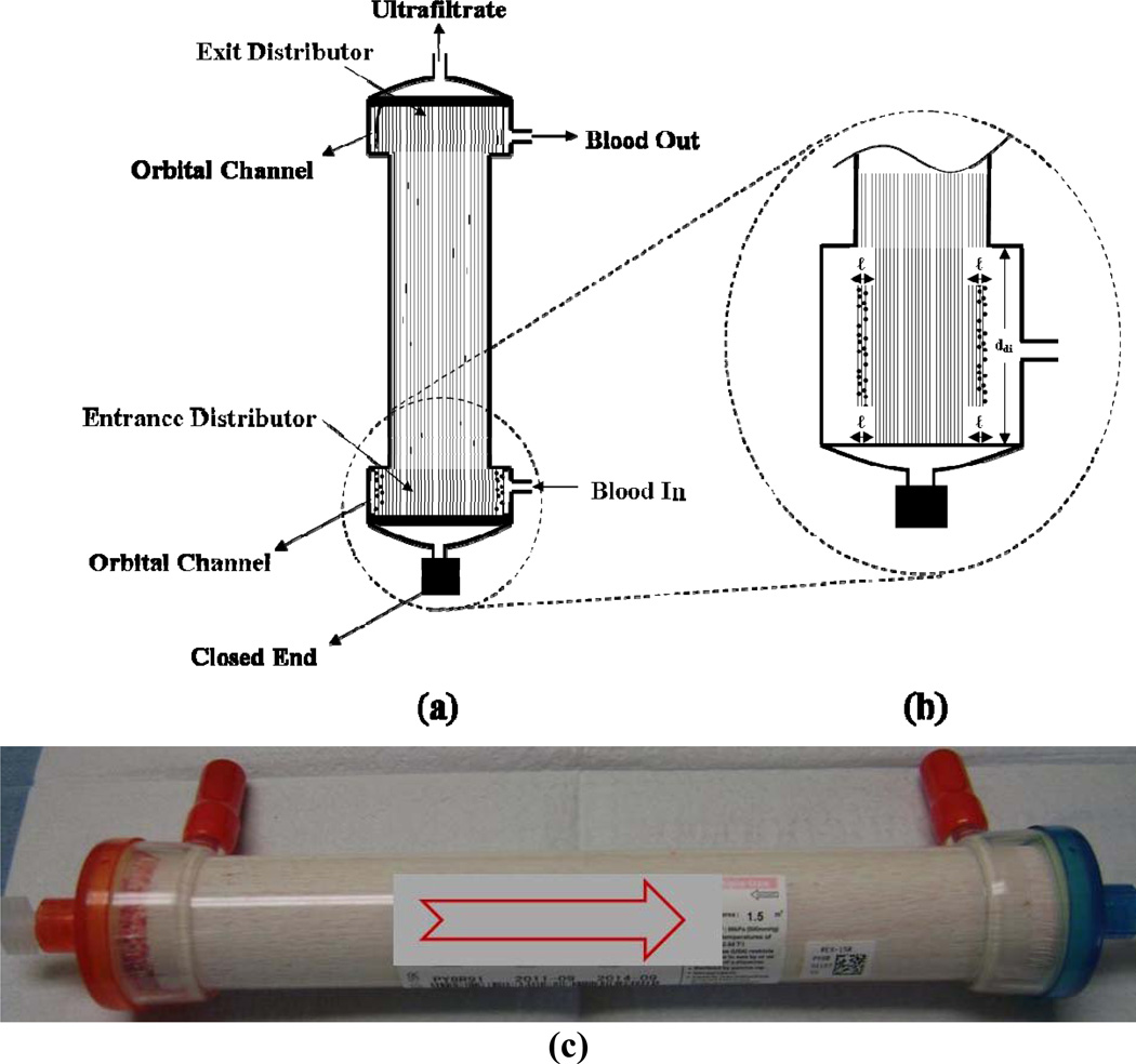
In vitro hemofiltration experiments were performed with bovine blood purchased from Lampire Biological Laboratories (Pipersville, PA). Heparin was added at concentrations ranging from 2.5 to 10 IU/mL. Blood flow rates were varied between 75 and 300 mL/min, using ultrafiltrate flow rates from 1.5 – 2.0 mL/min. During outside-in operation, the filter was positioned vertically with blood introduced from the bottom dialysate port and exiting from the top dialysate port. Ultrafiltrate was collected from the top lumen port with the bottom lumen port closed (Figure 6). Both low flux (Kuf ≤ 10 ml/hr/mmHg) and high flux hemodialyzers and hemofilters were examined (Table 1).
Figure 6.
Axial cross section showing the typical clot distribution after long-term operation (100 hours) using outside-in hemofiltration. (a) Overall thrombi distribution; (b) Enlarged profile of the entrance section and (c) Picture of filter after 100 hours.
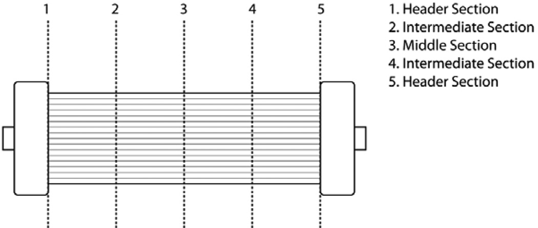
Experiments were normally terminated when the axial pressure drop between the inlet and outlet of the filter reached a value between 250 and 300 mmHg. Blood was changed daily without flushing the filter to appropriately simulate the conditions needed for long-term continuous hemofiltration. Immediately after filter failure, the filter was rinsed with saline to remove all visible blood. Visual observations were made to determine the mode and distribution of thrombi in the various sections of the filter. The filter was then dissected by cutting cross-sections along its length as depicted in Figure 3. The results were documented by digital photography and microscope examination using an inverted microscope (Bausch & Lomb) at several magnifications between 3× and 10×. The spatial distribution (from periphery to center) and size of any thrombi were determined in each fiber section.
Figure 3.
Schematic of sectioning along filter length used for microscopic examination of thrombi.
4. Results and Discussion
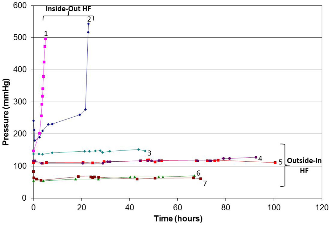
Figure 4 shows the axial pressure drop (blood inlet minus blood outlet) as a function of time for long-term blood processing performed with the Asahi Rexeed® 15R and 15LX hemodialyzers using both conventional (intra-luminal) and outside-in hemofiltration. The two repeat experiments using conventional hemofiltration showed unacceptable pressure drops (greater than 300 mm Hg) after less than 25 hr (and in one case after only 5 hr). The small decline in pressure at the very end of these experiments was due to the inability of the blood (feed) pump to maintain a constant flow rate under these conditions. In contrast, operation using the outside-in configuration provided stable operation for up to 100 hr. It is likely that these filters could be used for much longer filtration runs given the very small (typically less than 20 mm Hg) increase in pressure after even 100 hr of operation. This improved performance was seen over a range of blood flow rates (100 to 200 mL/min) and using both low flux (Asahi Rexeed® 15LX) and high flux (15R) modules. Similar results were obtained with the other filters listed in Table 1, with all filters showing at least 100 hr of continuous operation when used in the outside-in configuration.
Figure 4.
Axial pressure drop as a function of time for modules operated using conventional (intra-luminal) and outside-in hemofiltration. Designation: 1 – Conventional HF (Asahi Rexeed® 15R; Qb = 200 ml/min); 2 - Conventional HF (Asahi Rexeed® 15R; Qb = 200 ml/min); 3 – Outside-In HF (Asahi Rexeed® 15LX; Qb = 200 ml/min); 4 - Outside-In HF (Asahi Rexeed® 15R; Qb = 200 ml/min); 5 - Outside-In HF (Asahi Rexeed® 15R; Qb = 200 ml/min); 6 - Outside-In HF (Asahi Rexeed® 15R; Qb = 100 ml/min); 7 - Outside-In HF (Asahi Rexeed® 15R; Qb = 100 ml/min)
A very simple mathematical model for the increase in axial pressure drop seen with intra-luminal (conventional) operation was developed using the classical fouling model based on fiber (or pore) blockage [16]:
| (9) |
where α is the fiber blockage parameter and t is the filtration time. Although the actual situation is likely to be quite complex, with some degree of fiber constriction due to blood cell deposition as well as partial fiber blockage by smaller thrombi, Equation (9) does correctly predict that the pressure rises very rapidly at a critical time t = 1/α when all of the fibers become blocked. Based on the data in Figure 4, the fibers become fully blocked after between 6 and 24 hr. In contrast, for the outside-in configuration (n ≈ 10 N after 100 hr of operation), Eq. (3) predicts an increase in axial pressure drop of only 3%, which is in fairly good agreement with the results in Figure 4.
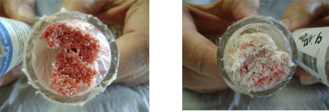
Visual examination of failed filters used in the conventional mode showed that the lumens of the hollow fibers became clotted with thrombi mostly within the first 1 to 2 cm from the entrance header (left panel, Figure 5) with minimal clotting observed in the downstream regions (right panel, Figure 5). This finding was consistent for all filter types and membrane materials when used for conventional hemofiltration.
Figure 5.
Photos showing filter clotting during conventional (intra-luminal) hemofiltration near the filter entrance (left) and exit (right).
In contrast to the results in Figure 5, the modules used for outside-in hemofiltration showed a small number of isolated thrombi distributed within the main section of the fiber bundle past the entrance zone of the distributor. There was a clear indication of visible clot formation in the entrance zone of the filter within the distributor section where blood enters the fiber bundle, while the exit distributor was mostly clean with no visible clots (Figure 6). Microscopic examination of the fiber bundle after long-term hemofiltration showed a very low volume fraction of small size thrombi disperse within the bundle. There were no observable differences in the number or distribution of thrombi between the low and high flux dialyezrs.
Limited experiments were also performed with the Minntech Renaflo Mini® hemofilter made without the orbital distributor that is used to provide better flow distribution in the inter-fiber space of the module [17]. Although this module could still be used for as much as 94 hours in the outside-in configuration, it showed a large extended clot in the space between the outer shell and the fiber bundle where blood enters the system (Figure 7). Other clots were also found within the large irregular spaces of the fiber bundle. These results clearly demonstrate the importance of uniform flow within the inter-fiber space during outside-in hemofiltration.
Figure 7.
Clotting pattern in the Minntech Renaflo-Mini hemofilter operated without the orbital distributor after 94 hrs. of operation using the outside-in configuration. (a) Picture of typical clot formed in space between entrance to IFS and filter housing and (b) Schematic of thrombi distribution profile.
The results in Figures 4 through 7 were obtained using 10 IU/mL of heparin. Hemofiltration experiments performed with only 2.5 IU/mL showed severe clotting during handling. Data obtained with a heparin concentration of 5 IU/mL showed more thrombi formation in the entrance zone compared to that seen with 10 IU/mL, although these filters could still be successfully operated for >100 hr. Thrombus deposition was also greater when using higher blood flow rates (e.g., 300 mL/min), although there was still relatively little increase in axial pressure drop over 100 hr of operation (data not shown).
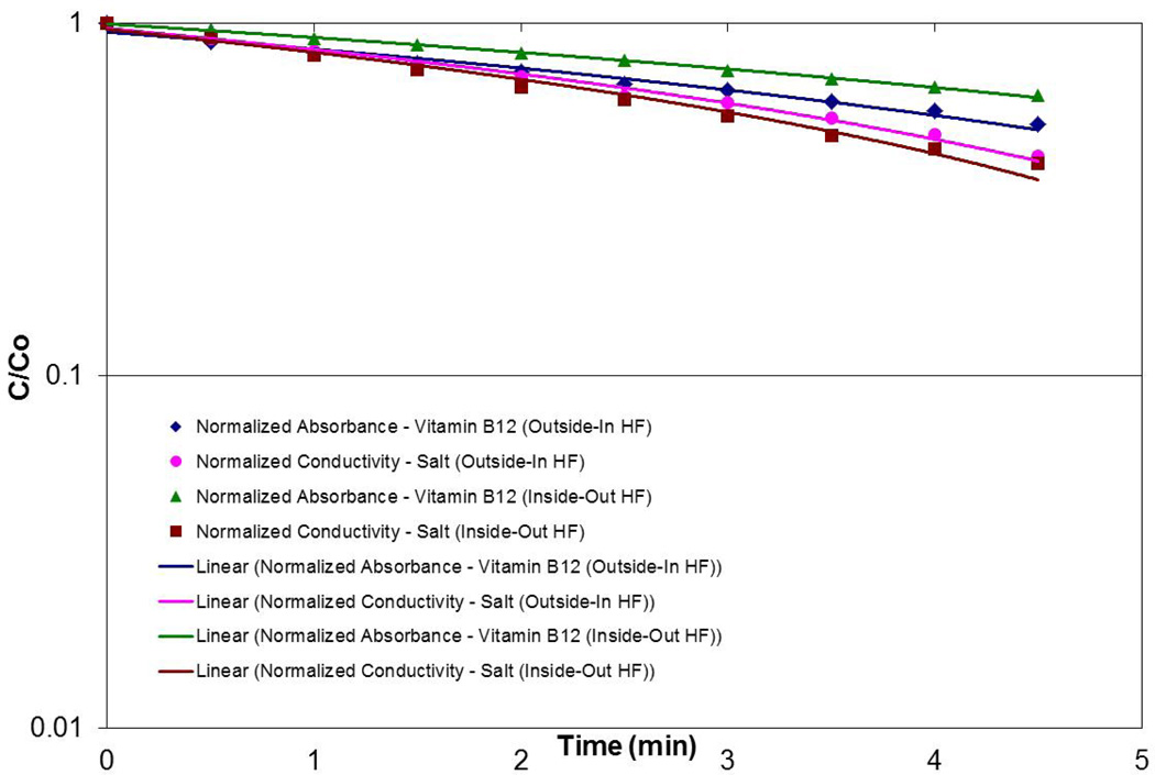
In order to demonstrate that the outside-in configuration provided adequate solute removal, clearance experiments were performed using NaCl and vitamin B12. Typical data for the Asahi Rexeed® 15R module are shown in Figure 8 for the solute concentration in a “blood” reservoir as a function of time (where the reservoir was filled with water containing the solutes). The clearance can be calculated directly from the slope of the data on a semi-log plot [15]. The calculated clearance for both NaCl and vitamin B12 were statistically identical in the two flow configurations, demonstrating that outside-in hemofiltration can provide adequate solute clearance for clinical applications in treatment of renal failure.
Figure 8.
Clearance of NaCl and vitamin B12 for the Asahi Rexeed® 15R module using conventional and outside-in hemofiltration.
5. Conclusions
The data obtained in this study clearly demonstrate that the use of an outside-in configuration dramatically increases the lifetime of hemofiltration modules during blood filtration. This increase is a direct result of the hydrodynamic advantage of the outside-in mode of hemofiltration. When the hollow fiber module is operated with conventional (intra-luminal) flow, thrombi deposited within the fiber lumens cause a significant increase in the axial pressure drop and a maximum life of less than 30 hr. This effect is not seen when using the outside-in configuration due to the 3-dimensional interconnected hydrodynamic flow channels in the inter-fiber space. The small volume fraction of trapped thrombi observed in the inter-fiber region causes only a small increase in axial pressure drop (less than 20 mm Hg), consistent with predictions of the simple mathematical model developed in Section 2. A small thrombus trap could easily be used in the return blood line to insure that no shed thrombi are returned to the patient. The much longer operation possible with the outside-in configuration would reduce filter replacement costs, minimize blood loss, significantly reduce nursing requirements, minimize disturbances in patient blood pressure, and reduce the likelihood of infection.
The low level of thrombi formation seen during outside-in operation is likely due to a number of phenomena. First, the gaps between fibers are considerably larger than the 200 µm inner diameter of the hollow fibers. Second, it is possible that albumin deposited on the external surface of the fibers may protect against platelet adhesion [18]. This phenomenon may be more important in the outside-in configuration due to the greater degree of concentration polarization associated with the somewhat lower mass transfer coefficient in the inter-fiber space. It is also possible that there is some protection associated with the asymmetric structure of the hollow fiber membranes, with the surface facing the blood now having a larger pore size. Third, the lower shear rate in the inter-fiber space may reduce clot formation; data obtained with higher blood flow rates clearly showed greater thrombus deposition near the device inlet when using the outside-in configuration. Thrombus deposition also increased at low heparin concentrations due to the development of bulk thrombi (emboli) within the blood.
It may well be possible to use outside-in hemofiltration at lower heparin concentrations and/or for longer times by re-designing the inter-fiber space to provide more uniform flow distribution and/or by adding an emboli trap in the blood flow path immediately before the entrance to the filter. For example, a more axially uniform flow within the IFS could be achieved by appropriate modification of the entrance header. It would also be possible to consider other filter configurations (e.g, employing radial flow) to ensure more uniform blood flow in the inter-fiber space. Such enhanced hemofiltration modules could potentially enable successful long-term renal replacement therapy and treatment of hypervolemia in congestive heart failure patients.
Outside-in hemofiltration provides >100 hr continuous operation
Visual observation show thrombi remain isolated in inter-fiber space
Thrombi have minimal impact due to interconnected flow in inter-fiber space
Simple model developed for flow and pressure drop for outside-in configuration
Low anticoagulant concentrations lead to blood instability and emboli
Acknowledgments
The authors acknowledge funding for this research from the National Heart, Lung, and Blood Institute, National Institutes of Health (Grant Number 1R43HL105178-01) and the National Institute of Diabetes and Kidney Diseases, National Institutes of Health (Grant Numbers 1R43DK55419-01, 2R44DK055419-02A1 and 2R44DK055419-04A1).
Footnotes
Publisher's Disclaimer: This is a PDF file of an unedited manuscript that has been accepted for publication. As a service to our customers we are providing this early version of the manuscript. The manuscript will undergo copyediting, typesetting, and review of the resulting proof before it is published in its final citable form. Please note that during the production process errors may be discovered which could affect the content, and all legal disclaimers that apply to the journal pertain.
References
- 1.Uchino S, Fealy N, Baldwin I, Morimatsu H, Bellomo R. Continuous is not continuous: the incidence and impact of circuit “down-time” on uraemic control during continuous veno-venous haemofiltration. Intensive Care Med. 2003;29:575–578. doi: 10.1007/s00134-003-1672-8. [DOI] [PubMed] [Google Scholar]
- 2.Brophy PD, Somers MJG, Baum MA, Symons JM, McAfee N, Fortenberry JD, Rogers K, Barnett J, Blowey D, Baker C, Bunchman TE, Goldstein SL. Multi-centre evaluation of anticoagulation in patients receiving continuous renal replacement therapy (CRRT) Nephrol Dial Transplant. 2005;20:1416–1421. doi: 10.1093/ndt/gfh817. [DOI] [PubMed] [Google Scholar]
- 3.Hofbauer R, Moser D, Frass M, Oberbauer R, Kaye AD, Wagner O, Kapiotis S, Druml W. Effect of anticoagulation on blood membrane interactions during hemodialysis. Kidney Int. 1999;56:1578–1583. doi: 10.1046/j.1523-1755.1999.00671.x. [DOI] [PubMed] [Google Scholar]
- 4.Buzat P, Zsirai T, Aerts P, Judd SJ. Permeability and clogging in an immersed hollow fibre membrane bioreactor. J. Membrane Sci. 2012;421–422:342–348. [Google Scholar]
- 5.Stefanski M, Kennedy S, Judd SJ. The determination and origin of fibre clogging in membrane bioreactor. J. Membrane Sci. 2011;375:198–203. [Google Scholar]
- 6.Gaylor JDS. Membrane oxygenators: Current developments in design and application. J. Biomed. Eng. 1988;10:541–547. doi: 10.1016/0141-5425(88)90113-6. [DOI] [PubMed] [Google Scholar]
- 7.Unger JK, Janssen VR, Kashefi A, Haltern C, Klosterhalfen B, Fischer Y, Gressner AM, Rossaint R. Enhancing filtration rates by the use of blood flow around the capillaries of plasmafilters: an in vitro study. Int J Artif Organs. 2001;24(11):821–831. [PubMed] [Google Scholar]
- 8.Herzig JP, LeClerc DM, Le Goff P. Flow of suspensions through porous media: Application to deep filtration. Ind. Eng. Chem. 1970;62:8–35. [Google Scholar]
- 9.Ives KJ. Deep bed filters. NATO ASI Ser. 1985;88:90–149. [Google Scholar]
- 10.Tien C, Payatakes AC. Advances in deep bed filtration. AIChE J. 1979;25:737–759. [Google Scholar]
- 11.Ho C-C, Zydney AL. Effect of membrane morphology on protein fouling during microfiltration. J. Membrane Sci. 1999;155:261–276. [Google Scholar]
- 12.Zydney AL, Ho C-C. Effect of membrane morphology on system capacity during normal flow microfiltration. Biotech. Bioeng. 2003;83(5):537–543. doi: 10.1002/bit.10699. [DOI] [PubMed] [Google Scholar]
- 13.Fraser KH, Zhang T, Taskin ME, Griffith BP, Wu ZJ. Computational fluid dynamics analysis of thrombosis potential in left ventricular assist device drainage cannulae. ASAIO J. 2010;56(3):157–163. doi: 10.1097/MAT.0b013e3181d861f1. [DOI] [PMC free article] [PubMed] [Google Scholar]
- 14.Happel J, Brenner H. Low Reynolds Number Hydrodynamics. Prentice Hall: 1965. [Google Scholar]
- 15.Morti SM, Zydney AL. Protein-membrane interactions during hemodialysis. Am. Soc. Artif. Internal Organs J. 1998;44:319. doi: 10.1097/00002480-199807000-00015. [DOI] [PubMed] [Google Scholar]
- 16.Hlavacek M, Bouchet F. Constant flow-rate blocking laws and an example of their application to dead-end microfiltration of protein solutions. J. Membrane Sci. 1993;82:285. [Google Scholar]
- 17.Brendolan A, Nalesso F, Fortunato A, Crepaldi C, De Cal M, Cazzavillan S, Cruz D, Techawathanawanna N, Ronco C. Dialytic performance evaluation of Rexeed™: A new polysulfone-based dialyzer with improved flow distributions. Int. J. Artif. Organs. 2005;28(10):966–975. doi: 10.1177/039139880502801003. [DOI] [PubMed] [Google Scholar]
- 18.Sivaranian B, Latour RA. The adherence of platelets to adsorbed albumin by receptor-initiated recognition of binding sites exposed by adsorption-induced unfolding. Biomaterials. 2010;31:1036. doi: 10.1016/j.biomaterials.2009.10.017. [DOI] [PMC free article] [PubMed] [Google Scholar]


