Abstract
Purpose
To demonstrate the use of forced current excitation (FCE) to create homogeneous excitation of the breast at 7T, insensitive to the effects of asymmetries in the electrical environment.
Materials and Methods
FCE was implemented on two breast coils: one for quadrature 1H imaging and one for proton-decoupled 13C spectroscopy. Both were a Helmholtz-saddle combination, with the saddle tuned to 298 MHz for imaging and 75 MHz for spectroscopy. Bench measurements were acquired to demonstrate the ability to force equal currents on elements in the presence of asymmetric loading to improve homogeneity. Modeling and temperature measurements were conducted per safety protocol. B1 mapping, imaging, and proton decoupled 13C spectroscopy were demonstrated in vivo.
Results
Using FCE to ensure balanced currents on elements enabled straightforward tuning and maintaining of isolation between quadrature elements of the coil. Modeling and bench measurements confirmed homogeneity of the field, which resulted in images with excellent fat suppression and in broadband proton decoupled carbon-13 spectra.
Conclusion
FCE is a straightforward approach to ensure equal currents on multiple coil elements and a homogeneous excitation field, insensitive to the effects of asymmetries in the electrical environment. This enabled effective breast imaging and proton decoupled carbon-13 spectroscopy at 7T.
Keywords: Transmit coil, 7T, Breast MRI
INTRODUCTION
Diagnostic breast MRI at 1.5T and 3T offers high resolution morphological delineation and tissue contrast, diffusion and perfusion functional imaging, and assessment of tissue metabolic composition with MR spectroscopy (1-9). A new generation of MR studies of the breast may be afforded by the improved sensitivity and chemical shift dispersion provided by the recent availability of commercial whole-body 7T scanners. The technical challenges at 7T are significant compared to lower field strengths, however, including an increase in B1 inhomogeneity, SAR, and an increased sensitivity of coils to loading. One approach for addressing these issues is to drive multiple transmit coils using multiple independent amplifiers, i.e., B1 shimming (10,11) or Transmit SENSE (12,13). These are expensive and complex approaches that may not be available for routine clinical research for some time but may be essential for optimal head and body imaging. Such approaches, however, may not be necessary to effectively image isolated anatomies. For instance, high quality images of smaller structures such as the knee (14,15) have been obtained at 7T using a single transmit channel. The breast presents a more challenging anatomy to image at 7T, however, because of its proximity to the thorax that brings about a significantly asymmetric influence on B1 in the breast. This paper presents an RF coil design that overcomes this issue by using transmission line techniques to force equal currents on multiple elements to generate homogeneous quadrature excitation of the breast at 7T using a single transmitter.
Transmission line techniques to ensure equal currents on array elements with different impedances were introduced more than 50 years ago for broadcast antennas (16,17). The method, termed forced current excitation (FCE), has been investigated previously for use with MRI for mitigating coupling in high channel count arrays of microcoils (18) but the technique has not been applied to coils intended for in vivo use. Here we report the development and application of the FCE design to overcome the effects at 7 tesla of the asymmetric loading conditions present when imaging the breast. By forcing equal currents on the elements of a coil, two main benefits were realized: 1) B1 homogeneity was achieved without the need for multiple transmitters, and 2) the robustness provided by maintaining equal currents on multiple elements in the face of highly varying and asymmetric loads enabled tuning and maintaining of isolation between quadrature elements. The load-insensitive homogeneity and efficiency of the quadrature design make the coil particularly well suited for the straightforward addition of a receive array insert, for performing localized 1H spectroscopy, and for serving as the transmitter for the broadband 1H decoupling often employed in non-proton spectroscopy. This paper discusses the theory of forced current excitation, the design and construction of the FCE quadrature breast coil for 7T, and demonstrates the effectiveness of the design with in vivo imaging and broadband decoupled 13C spectroscopy.
THEORY
Effects of asymmetric loading as a function of field strength
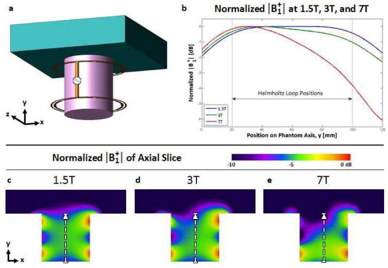
MR imaging of the breast is typically performed with the patient in a prone position and the breast pendant in order to avoid respiratory artifacts and improve image quality (2,4). Therefore solenoidal coils and Helmholtz pairs historically have proven to be effective RF coil designs for breast imaging at 1.5T and 3T, generating a volume of homogeneous vertically directed field in the pendant breast with effective penetration into the chest wall (4,19-25). At 298MHz (7T), however, the unequal loading between the top of the coil near the thorax and the lower part of the coil away from the body results in a unequal currents on the loops of the Helmholtz pair and thus inhomogeneous excitation. This is illustrated in Fig. 1 by the modeled comparison of a conventionally driven Helmholtz pair (two 16 cm loops with 8 cm coaxial spacing) exciting an asymmetric phantom at 1.5T, 3T, and 7T. The phantom was designed to mimic the breast and thorax and will be discussed in more detail below. The notable point at 7T as opposed to 1.5T or 3T is the 6dB drop in sensitivity from the bottom of the “breast” to where it meets the “thorax”. Generating equal currents on the two loops of the Helmholtz pair would in turn ensure a homogeneous field, but can be complex to implement. One approach would be to use a multiple channel transmitter with independent control of each amplifier. Coupling between elements is a complicating factor, but even this can be overcome in principle by using some form of current source amplifier (26-28). Lacking multiple transmit channels, one could design some form of tuning network to create equal currents on each element. Theoretically, this could be accomplished using current probes on each loop to provide feedback for independent tuning of the top and bottom loop in the presence of the asymmetric loading – a complex approach not practical for use with patients. This paper describes a specialized power splitter which enforces equal current, rather than equal power, at the feedpoints of the two loops independent of the loading conditions on either loop, thus generating a homogeneous excitation. We refer to this method as forced current excitation (FCE).
Figure 1.
Comparison of modeled |B1+| as a function of field strength produced by a Helmholtz coil with an asymmetric load that mimics imaging the pendant breast proximal to the thorax. (a) Rendering of the conventional, parallel-fed Helmholtz coil with an asymmetric phantom comprised of the electrical characteristics of breast tissue inside and the thorax above. (b) Profiles through the marked areas in (c)-(e) depicting |B1+| at 1.5T (63.9MHz), 3.0T (128MHz), and 7.0T (298MHz). The effects of the asymmetric loading of the thorax on the current distribution on the two loops of the Helmholtz coil increases with frequency, resulting in a 6dB fall off towards the thorax at 7.0T.
Forced Current Excitation
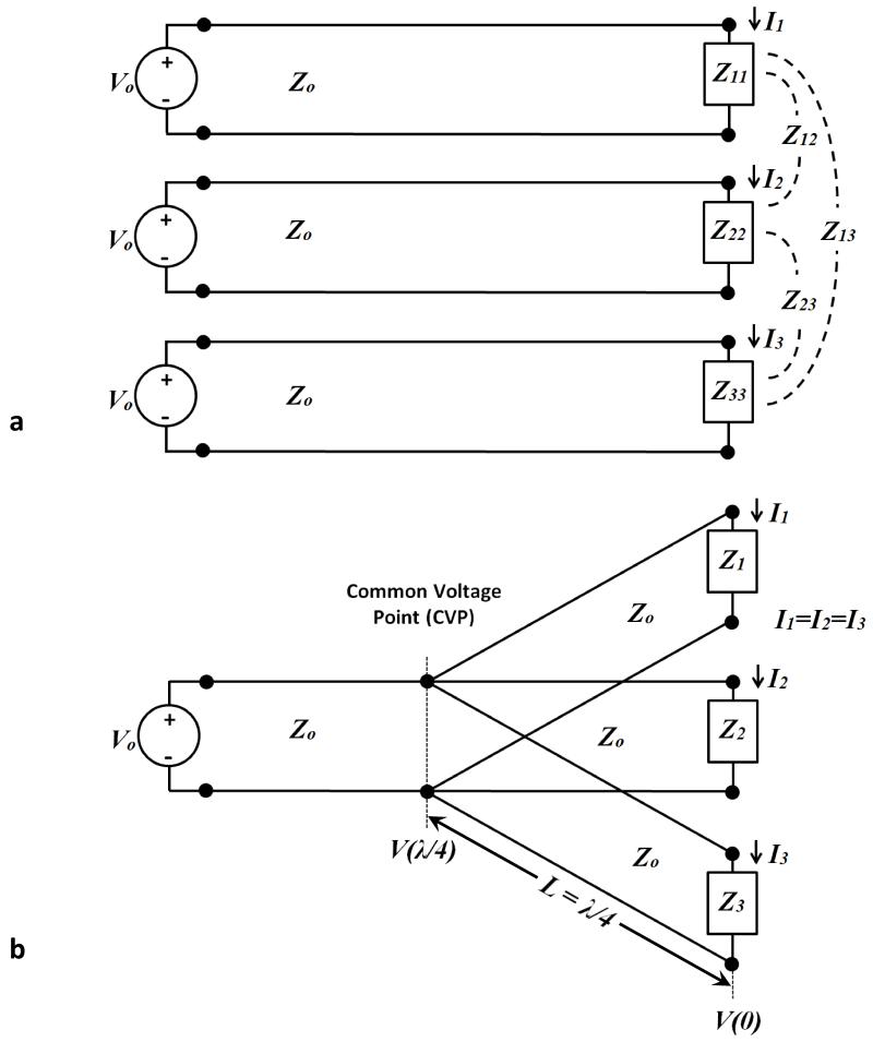
Conventionally, RF coils are driven in a “free-excitation” model, where a voltage source is controlled, and the current in the elements becomes dependent on the load impedance, as illustrated in Fig. 2a. However, as a consequence of asymmetries introduced by the specific anatomy (such as the thorax) as well as the electrical environment from tuning elements, receive coils, etc., the impedance presented to the voltage source will vary with its loading, as well as with the loading in the adjacent elements. The effects of asymmetric loading in a free excitation model as a function of field strength were demonstrated in the previous section, and are particularly prevalent at 7 tesla. To avoid this, “forced current excitation” (FCE) can be created, in which the current at the element feed ports can be made independent of the load impedance. This is illustrated in Fig. 2b, where the individual RF elements share a common feed port at an electrical distance of γ/4. Transmission line analysis of each feed line to any of the loads relates the voltage on the transmission line, the load impedance, and the load current as
| (1) |
where β is the propagation constant in the transmission line, z is the physical distance measured from the load,ZL is the active impedance of the array element (which is generally different than its isolated input impedance), Z0 is the characteristic impedance of the transmission line, V (z) is the voltage and IL is the load current. In the special case where the transmission lines connecting the element feed points to a common voltage point are an electrical quarter wavelength (as shown in Fig. 2b), Eq. 1 simplifies to:
| (2) |
After simplifying Eq. 2, the impact of the load impedance disappears and it can be shown that the load current depends only on the characteristic impedance of the line and the voltage at the common feed point:
| (3) |
It should be noted that the voltage at the common voltage point (CVP) is indeed dependent on the load values, as is the actual value of the load current, IL . What the “forced current excitation” approach ensures, however, is that all the load currents are the same, regardless of differences in the load values, as long as all the elements are connected to the CVP through electrical quarter wavelength lines. As will be shown below, enforcing equal current at the different RF element ports results in improved B1+ homogeneity over free excitation in highly asymmetric loading conditions, as is the case in excitation of the pendant breast. It is worth noting that throughout the text, B1+ notation will be used where appropriate to indicate specific reference to properties of the transmitted field, though we operated in transmit-receive mode.
Figure 2.
Comparison of free excitation and forced current excitation (FCE). (a) Schematic illustration of three coils, identical or non-identical, excited by the same voltage. This configuration is termed “free excitation”. Asymmetries in positioning or environment, combined with the mutual impedances between coils generally leads to unequal load impedances presented to the sources, resulting in unequal currents despite identical excitation. (b) When connected to a common voltage point (CVP) by electrical quarter wave lines the feed currents are the same regardless of differences in the load impedances, effectively achieving “forced current excitation”.
METHODS
Coil Construction
Two coils were constructed which used the forced current technique: one for quadrature 1H imaging and one for proton-decoupled 13C spectroscopy. Henceforth these will be referred to as the “imaging coil” and the “spectroscopy coil”, respectively. Both coils consisted of a Helmholtz-saddle combination, with the saddle tuned to 298 MHz for the quadrature imaging coil and tuned to 75 MHz (13C) for the spectroscopy coil.
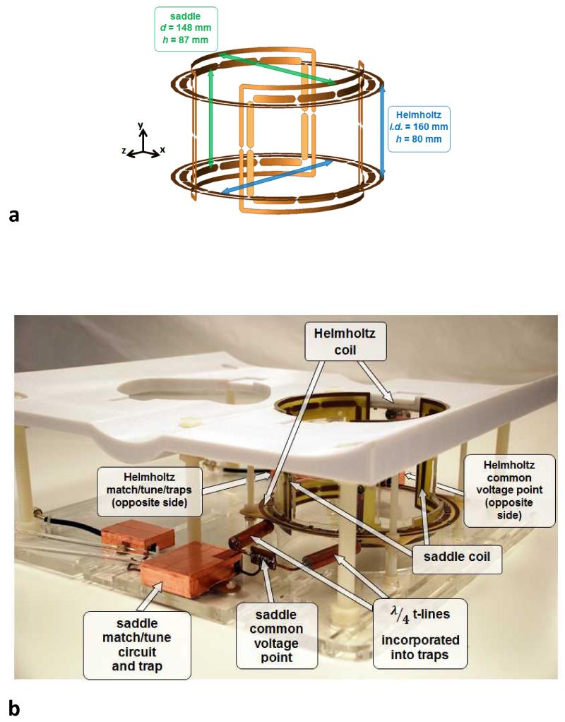
The Helmholtz component of the imaging coil was constructed from two identical loops (i.d. 16.0 cm, o.d. 17.2 cm, co-axial spacing 8.0 cm) to produce y-directed B1 field. The saddle coil (diameter 15.3 cm, length 8.7 cm, aperture angle 120°, conductor width 0.6 cm) was constructed from two elements, affixed on opposite sides of a cylindrical former, and centered inside the Helmholtz coil, producing x-directed B1 field. A dimensioned illustration is shown in Fig. 3a. Both the Helmholtz pair and the saddle pair were FCE-driven, enabling robust and straightforward/insensitive matching and tuning in quadrature due to the enforced equal currents ensuring symmetry. All coil elements were fabricated from industry-standard copper-clad FR-4 PCB and segmented by eleven 12.1pF capacitors. Each element was also surrounded by a parallel co-planar shield (conductor width 0.4 cm, spaced 0.4 cm from element) segmented in two places with 1800 pF capacitors. FCE was implemented separately for the Helmholtz and saddle coils, with both elements in each coil pair connected to a common voltage point through quarter-wavelength coaxial cables. Traps integrated in the quarter-wavelength cables ensured current suppression on the outside of the coaxial shield. The match and tune circuit for each coil pair was connected to its common voltage point (CVP) by a length of coaxial cable chosen to facilitate matching to 50 Ω. Two identical coaxial cables with additional integrated traps connected the quadrature coil to the MR system. A photograph of the imaging coil is shown in Fig. 3b, with the relevant cable lengths and components labeled.
Figure 3.
Rendering and photograph of the quadrature Helmholtz – saddle FCE coil. (a) 3D rendering of the coil with gaps for capacitors and dimensions shown. (b) photograph of the completed quadrature coil with important features marked.
The Helmholtz component of the spectroscopy coil consisted of two identical loops (i.d. 14.8 cm, o.d. 16.0 cm, co-axial spacing 7.4 cm) surrounded by a parallel co-planar shield that provided uniform proton decoupling over the volume of the breast when driven with FCE. A conventionally driven, unshielded saddle coil was used for 13C transmission and reception (diameter 13.2 cm, length 8.0 cm, aperture angle 121°, conductor width 0.6 cm).
Electromagnetic Modeling & Bench Measurements
Commercial FDTD simulation software (Remcom XFdtd 7.1, State College, PA) was used to perform electromagnetic modeling for determining safe operating parameters. The 5 mm resolution High Fidelity Female Body Mesh provided by NMR Hershey (Center for NMR Research, Pennsylvania State University, College of Medicine at Hershey) and distributed by Remcom was designed with the body in the supine position and therefore was not conducive to filling the interior of the volume coil when in the prone position. Therefore, for SAR evaluation, a geometric phantom was generated consisting of a cylinder with the electrical properties of breast tissue spaced 1 cm inside of the coil conductors. The cylinder was connected to a rectangular region with the properties of muscle to represent the thorax. Electrical properties of the breast and thorax regions of the phantom were obtained from (29), with conductivity σ = 0.04 S/m and relative permittivity εr = 5.64 for breast tissue, and σ = 0.77 S/m and relative permittivity εr = 58.2 for the thorax. The coil volume was discretized on a 1 mm grid and each FCE element was fed with a 50 Ω, 1 A (steady state) current source to simulate the FCE drive condition.
To illustrate the benefits of FCE, bench measurements of field patterns for the 16.0-cm i.d. Helmholtz coil were obtained using an automated 3D positioning system reported previously (30). Field maps were acquired in an unloaded and in an asymmetrically loaded condition designed to mimic the presence of the thorax. The measurements were then repeated with the coil in a conventionally driven (non-FCE) configuration. To create the asymmetric loading conditions, a rectangular thorax phantom filled with 0.77 S/m saline solution was placed on top of the coil former. In all cases (unloaded, loaded, FCE, non-FCE), the coils were matched and tuned to 298 MHz and field measurements were acquired as S21 measurements (network analyzer HP 4395A) between the Helmholtz and a 4-mm i.d. shielded loop controlled by the automated positioner. It is worth noting that the saddle coil elements are symmetrically loaded by the thorax phantom; thus to illustrate the benefits of FCE, measurements were made on the Helmholtz coil only.
Imaging
All imaging and spectroscopy studies were conducted on a protocol approved by the local IRB. After obtaining written informed consent, data were acquired on a whole-body 7T scanner (Achieva, Philips Medical Systems, Cleveland, OH, USA). Surface and volume direct temperature measurements were performed in oil phantoms using Reflex fiber optic temperature measurement system (Neoptix Canada LP) following the Philips prescribed coil testing protocol to establish coil safety. Specifically, temperature was recorded before, during, and after the heating protocol. We used an RF intensive imaging protocol with 3% RF duty cycle, maximum B1+ = 20 μT, and a total scanning time of 10 minutes. The studies were carried out at room temperature (18-21°C, depending on the particular day of the experiment; temperature variation on a particular day was ±0.1°C), and each phantom was allowed to equilibrate for 10 minutes before the initiation of the RF heating studies. Temperature was measured both in the oil phantom and near the electrical elements on the coil and demonstrated marginal heating (less than 1°C), within safety guidelines (31).
Imaging was performed using the 1H unilateral quadrature breast coil described above in transmit/receive mode. The subjects were in prone position, with the head resting on pillows and with arms either to the side or above the head. The coil has openings on the sides of the saddle coil elements along the LR direction, which allows for access to the breast, such that the technologist can adjust the positioning of the subject. Each of the FCE coil pairs was tuned and matched per individual volunteer. Studies included the following: (a) B1+ mapping using dual TR method acquisition (32) with nominal flip angle of 50 degrees, TR1/TR2 = 35/140 ms, and resolution 2×2×10 mm, (b) fat suppressed 3D T1 weighted (THRIVE) sagittal, TR/TE=6.6/2.8ms, FA=8 degrees, two spatial resolutions – 0.8mm and 0.45mm cubic, 1:40 and 5:40 min acquisition, respectively, (c) SPAIR (Spectral Selection Attenuated Inversion Recovery) fat suppression (33), inversion delay=150ms and (d) 3D T2-weighted imaging (VISTA) with non-selective excitation, no fat suppression, sagittal, TR/TE=2000/100ms, TSE factor=67, FOV 250×200×105mm, 0.6 × 0.6 × 3.0mm acquired resolution). Maximum B1+ was limited to 20 μT in system software.
Broadband Proton-decoupled 13C MRS
Localized (ISIS, 50×50×50 mm) 13C spectra were acquired with the previously described “spectroscopy coil” by averaging 64 acquisitions with TR 13 s for a total scan time of 14:44 min. The large voxel was selected to compensate for the intrinsically low sensitivity of natural abundance 13C MRS. Since the goal of the study was fat composition analysis, however, the large voxel size did not represent a significant limitation as it would in the case of a lesion study. The repetition time was relatively long to mitigate SAR issues typical for proton-decoupled 13C MRS. Additionally, this choice benefited the MRS quantification since 13C T1s are relatively long. One offset was used, centered on the CH2 envelope of the fingerprint region (~ 29 ppm). WALTZ-16 decoupling with an 18 μT proton pulse centered at 1.3 ppm (for the fingerprint region) and NOE (10 μT at 5% duty cycle and a mixing time of 1.5 s) were used to simplify the spectra and enhance SNR. Scans were acquired with BW = 16 kHz and 2k points. Maximum B1+ for 13C was limited to 220 μT in software.
RESULTS & DISCUSSION
Modeling & Field Mapping
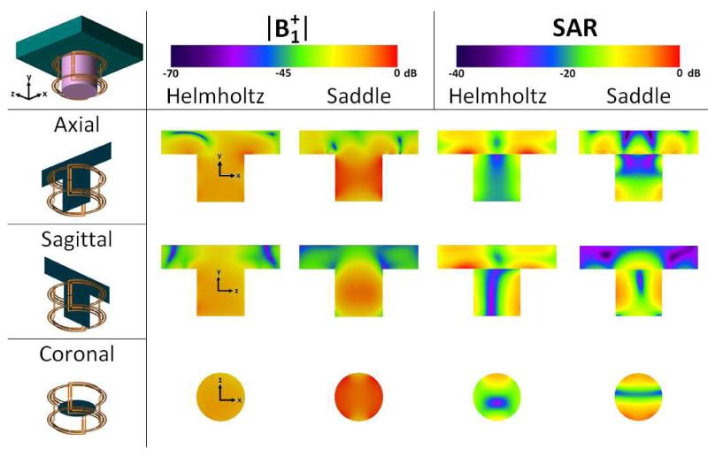
Modeled |B1+| values and SAR maps for the Helmholtz pair and the saddle pair are shown in Fig. 4, as generated by the Remcom XFdtd software in the phantom described above. The axial, sagittal, and coronal views are oriented with respect to the magnet axis (z). All three views are the isocenter plane. The benefit of the FCE approach, enforcing equal currents on the elements of the Helmholtz pair and saddle pair, is evident in the top-bottom symmetry in the SAR and |B1+| maps for the Helmholtz pair and in the left-right symmetry for the saddle pair despite the presence of asymmetric loading conditions. The asymmetries in the SAR modeling indicating increased SAR at the bottom of the saddle pair (seen in the axial modeling) and one side of the Helmholtz pair (seen in the sagittal and coronal modeling) are due to closer proximity to the feed points. Specifically, both elements of the saddle coil were excited on the −y side and both loops of the Helmholtz pair are excited on the +z side.
Figure 4.
|B1+| and SAR field plots generated by Remcom XFdtd. The phantom is a 12.0 cm diameter, 12.0 cm tall cylinder with the nominal properties of breast tissue connected to a 30.0 × 30.0 × 6.0 cm slab assigned the properties of muscle tissue, as described in the text. |B1+| plots demonstrate the homogeneity provided by the FCE design despite asymmetric loading. Asymmetries in the SAR plot are due to the feed locations on the Helmholtz and saddle pairs, as described in the text. The Helmholtz and saddle pairs were each normalized to 1 watt net input power. 0 dB corresponds to 2.0 μT and 1.47 W/kg in the |B1+| and SAR figures, respectively.
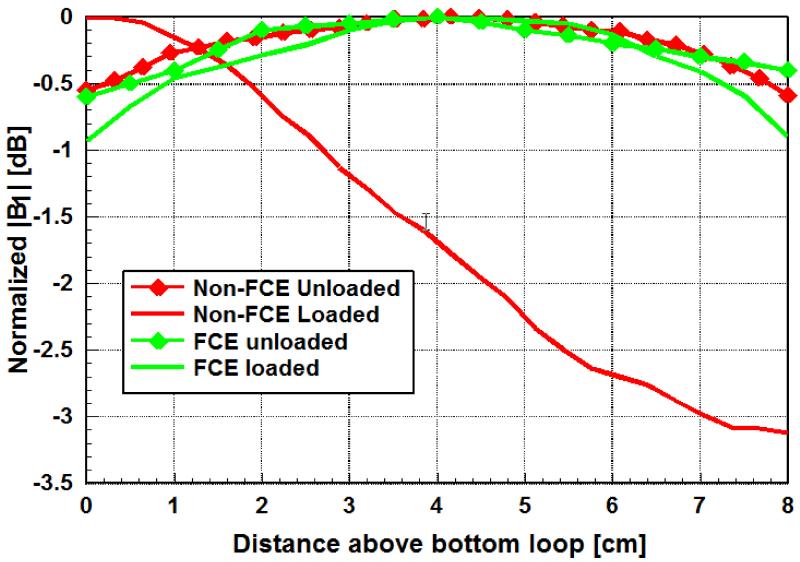
A comparison of field profiles between unloaded and asymmetrically loaded FCE and conventional Helmholtz coils is shown in Fig. 5, demonstrating the advantage of using FCE. The FCE driven pair created a homogeneous field in both the loaded and unloaded cases, confirming the presence of substantially equal currents on the two loops despite one of the loops being heavily loaded. Conversely, the presence of the heavy loading on one loop of the conventionally driven Helmholtz pair created a 3dB variation in the field intensity over the measurement range, in agreement with the electromagnetic modeling results shown in Fig. 1.
Figure 5.
Measured field profiles obtained as the S21 measurement between a shielded pickup loop and the Helmholtz coil in FCE and non-FCE mode, unloaded and asymmetrically loaded. Each profile is normalized to its respective maximum. The FCE maintains excellent homogeneity, comparable to the completely unloaded case, even in the presence of asymmetric loading.
It is important to note that there is no difference between the SAR and homogeneity of a conventionally driven coil that is tuned to achieve equal currents on the elements and the FCE coil; the point of the FCE design is the ability to realize the equal currents straightforwardly. Independent tuning of the elements could be quite cumbersome in practice, particularly given that the coupling between the saddle and Helmholtz pairs is not minimized until the current balance is achieved.
Imaging
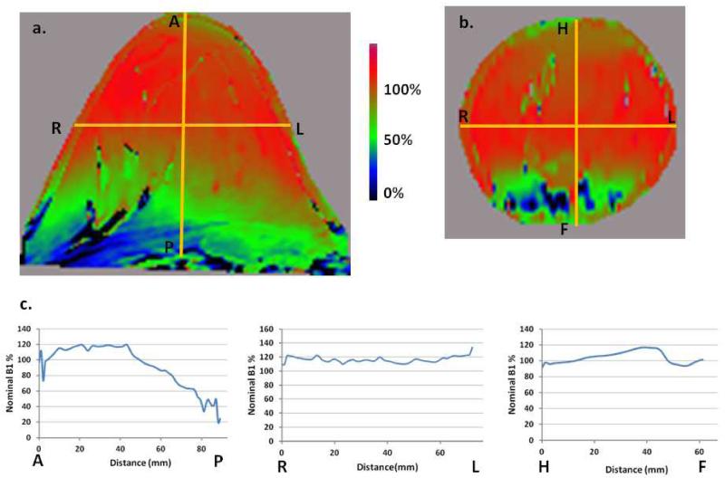
A B1+ map of a healthy volunteer is shown in Fig. 6. The anterior-posterior (AP) line profile (Fig. 6c) indicates approximately 1cm chest wall penetration. The B1+ coefficient of variation in the AP direction in the breast tissue is approximately 20%. The drop off into the chest wall is due to the fact that the breast did not fill the coil in this case. The anterior side of the breast is in the homogeneous center of the coil and, with coil padding in place for patient comfort and safety, the posterior side extends outside the coil FOV. A larger diameter coil would address this issue, but with the wavelengths associated with 7T, the benefits of a larger coil will need to be evaluated against the design challenges and potential loss of image quality. As expected, the B1+ profiles in the orthogonal directions (right-left (RL) and head-foot (HF) in Figure. 6) show much smaller variations (5-7%).
Figure 6.
B1+ map of a healthy volunteer. Power optimization was performed on the shim volume that included most of the breast volume proper. The nominal tip angle was 50 degrees and B1+ is shown as a percentage of that. (a) B1+ in the transverse plane as a percentage of nominal B1+. (b) B1+, coronal view. (c) B1+ AP, RL, and FH line profiles corresponding to the yellow lines in 6(a) and 6(b). The AP profile indicates approximately 1 cm penetration into the chest wall. The coefficient of variation of B1+ in AP direction in the breast tissue is approximately 20% in this case due to the posterior side of the breast extending outside the coil. The RL and HF profiles exhibit much smaller variations, 4% and 7%, respectively. The location of the HF profile line was chosen specifically to avoid the large anatomical null in the bottom center of the image.
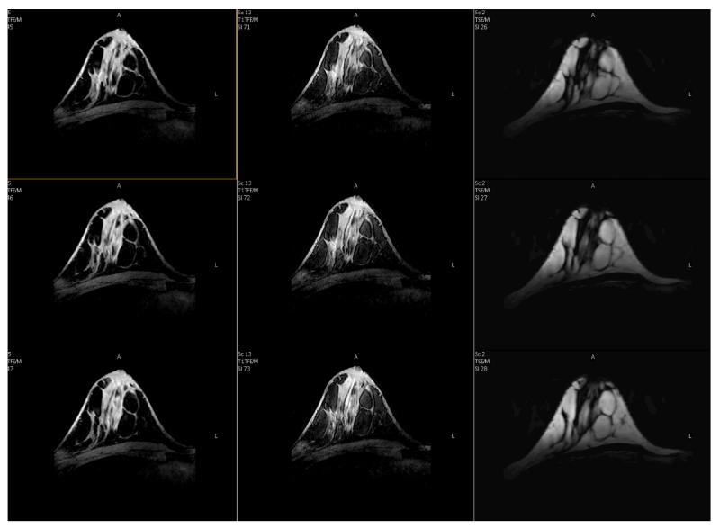
The first breast images acquired using the FCE quadrature coil are shown in Fig. 7. Three different sets of images are shown in the three columns. Upper and lower rows show adjacent slices. The left column is an isotropic T1W FFE 3D acquisition (voxel size 0.8 mm3) using SPAIR fat suppression. Quality of the fat suppression is noted as excellent with residual signal being just several times the background noise level. The middle column is the same technique with 0.45 mm3 voxels. Improved tissue margins are clearly observed on this ultra-high isotropic resolution image, and while its overall SNR is reduced as compared to the image acquired with the more clinically-used resolution of 0.8 mm3, it is still sufficient for clear visualization of the parenchyma. The ability to acquire images of such high resolution may lead to improvements in morphological characterization of tumors and their involvement in the surrounding tissues. The chest wall directly under the coil is also visualized, though with reduced intensity. Insufficient SNR is also noted in the region of the axilla. The right column shows 3D T2W TSE (0.6×0.6×3 mm3) without fat suppression. A certain amount of blurring is observed in these T2-w 3D TSE images since this sequence relies on long echo trains that will be affected by the expected decrease in tissue T2 at 7T. Modification of the echo train to include varying refocusing angles may alleviate this issue and preliminary work is underway (34).
Figure 7.
Breast images using FCE quadrature 1H breast coil. In columns: (left) T1W FFE 3D (0.80 mm3) with SPAIR fat suppression; (middle) T1W FFE 3D (0.45 mm3) with SPAIR fat suppression; (right) T2W TSE (VISTA) TSE (0.6 × 0.6 × 3.0 mm3). Note excellent suppression of the fat signal on T1W images, almost to the background level.
In vivo 13C MRS
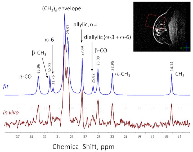
Broadband proton-decoupled 13C NMR spectrum from the right breast of a normal volunteer is shown in Fig. 8, along with the data fit (in blue). All expected major lipid 13C peaks in the fingerprint region are observed, showing no detectable decoupling artifacts (i.e. sidebands) over the entire acquisition bandwidth. In addition to the three fat fractions that can be obtained via proton MRS (saturated vs. mono-unsaturated vs. poly-unsaturated) as shown in (7), fitting the 13C spectrum allows for calculation of omega-6/omega-3 lipid ratio by the ratio of the diallylic (containing both omega-6 and omega-3) peak at 25.82 ppm and the omega-6 peak at 31.76 ppm (35). Further improvements in 13C coil sensitivity will be required in order to reliably discern these peaks in vivo and to achieve shorter acquisition times, and work is underway in this area.
Figure 8.
Broadband proton-decoupled 13C NMR spectrum from a healthy breast. (In this volunteer, the ratio omega-6/omega-3 = 1.94). The red square on the breast image insert represents the ISIS localization voxel.
CONCLUSION
Construction and optimization of safe and effective radiofrequency coils at 7T is a major challenge. The well-known interactions between transmit frequency and tissue dimensions and the increased sensitivity to loading at higher frequencies generate inhomogeneous B1 fields, degrading image quality. To address these challenges, this work discussed a forced current excitation feed technique applied to a unilateral 1H quadrature volume breast coil and a linear coil for proton decoupled 13C acquisition. The FCE design used transmission line properties to ensure equal currents at the feedpoints of the elements in a Helmholtz-Saddle configuration despite unequal loading on the elements due to asymmetries in the electrical properties of the anatomy, the presence of multiple elements, tuning components, etc. The insensitivity to loading simplified matching and tuning and enabled the elements of the quadrature coil to be easily decoupled. The homogeneity of the coil was demonstrated by achieving images with excellent fat suppression and with the ability to achieve broadband proton decoupling in 13C MRS.
This paper has presented an option to provide limited control of currents on array elements to create more homogeneous B1+ excitation patterns using a single amplifier. Future work will include improving SNR by adding an array coil insert and optimization of imaging and spectroscopy parameters.
ACKNOWLEDGMENTS
The authors gratefully acknowledge the support from the CPRIT (RP100625) and the NIH (EB015908). We also thank Jeannie Baxter, Salvador Pena, and Jing (Lilly) Yang for their assistance with the human subjects. We thank Samantha By for her assistance with fabrication and measurements.
Grant Support: Cancer Prevention and Research Institute of Texas, RP 100625
References
- 1.Berg WA, Gutierrez L, NessAiver MS, et al. Diagnostic Accuracy of Mammography, Clinical Examination, US, and MR Imaging in Preoperative Assessment of Breast Cancer1. Radiology. 2004;233(3):830–849. doi: 10.1148/radiol.2333031484. [DOI] [PubMed] [Google Scholar]
- 2.Hylton NM, Frankel SD. Imaging techniques for breast MR imaging. Magnetic resonance imaging clinics of North America. 1994;2(4):511–525. [PubMed] [Google Scholar]
- 3.Kuhl CK, Schrading S, Leutner CC, et al. Mammography, breast ultrasound, and magnetic resonance imaging for surveillance of women at high familial risk for breast cancer. Journal of clinical oncology. 2005;23(33):8469–8476. doi: 10.1200/JCO.2004.00.4960. [DOI] [PubMed] [Google Scholar]
- 4.Orel SG, Schnall MD. MR imaging of the breast for the detection, diagnosis, and staging of breast cancer. Radiology. 2001;220(1):13–30. doi: 10.1148/radiology.220.1.r01jl3113. [DOI] [PubMed] [Google Scholar]
- 5.Warner E, Messersmith H, Causer P, Eisen A, Shumak R, Plewes D. Systematic review: using magnetic resonance imaging to screen women at high risk for breast cancer. Annals of Internal Medicine. 2008;148(9):671–679. doi: 10.7326/0003-4819-148-9-200805060-00007. [DOI] [PubMed] [Google Scholar]
- 6.Bolan PJ, Meisamy S, Baker EH, et al. In vivo quantification of choline compounds in the breast with 1H MR spectroscopy. Magnetic resonance in medicine: official journal of the Society of Magnetic Resonance in Medicine/Society of Magnetic Resonance in Medicine. 2003;50(6):1134–1143. doi: 10.1002/mrm.10654. [DOI] [PubMed] [Google Scholar]
- 7.Dimitrov IE, Douglas D, Ren J, et al. In vivo determination of human breast fat composition by (1)H magnetic resonance spectroscopy at 7 T. Magnetic resonance in medicine: official journal of the Society of Magnetic Resonance in Medicine/Society of Magnetic Resonance in Medicine. 2012;67(1):20–26. doi: 10.1002/mrm.22993. [DOI] [PMC free article] [PubMed] [Google Scholar]
- 8.Haddadin IS, McIntosh A, Meisamy S, et al. Metabolite quantification and high-field MRS in breast cancer. NMR Biomed. 2009;22(1):65–76. doi: 10.1002/nbm.1217. [DOI] [PMC free article] [PubMed] [Google Scholar]
- 9.Hwang JH, Bluml S, Leaf A, Ross BD. In vivo characterization of fatty acids in human adipose tissue using natural abundance 1H decoupled 13C MRS at 1.5 T: clinical applications to dietary therapy. NMR Biomed. 2003;16(3):160–167. doi: 10.1002/nbm.824. [DOI] [PubMed] [Google Scholar]
- 10.Ibrahim TS, Hue Y-K, Tang L. Understanding and manipulating the RF fields at high field MRI. NMR in Biomedicine. 2009;22(9):927–936. doi: 10.1002/nbm.1406. [DOI] [PMC free article] [PubMed] [Google Scholar]
- 11.Mao W, Smith MB, Collins CM. Exploring the limits of RF shimming for high-field MRI of the human head. Magnetic Resonance in Medicine. 2006;56(4):918–922. doi: 10.1002/mrm.21013. [DOI] [PMC free article] [PubMed] [Google Scholar]
- 12.Zhu Y. Parallel excitation with an array of transmit coils. Magnetic Resonance in Medicine. 2004;51(4):775–784. doi: 10.1002/mrm.20011. [DOI] [PubMed] [Google Scholar]
- 13.Katscher U, Börnert P, Leussler C, van den Brink JS. Transmit SENSE. Magnetic Resonance in Medicine. 2003;49(1):144–150. doi: 10.1002/mrm.10353. [DOI] [PubMed] [Google Scholar]
- 14.Welsch GH, Juras V, Szomolanyi P, et al. Magnetic resonance imaging of the knee at 3 and 7 tesla: a comparison using dedicated multi-channel coils and optimised 2D and 3D protocols. Eur Radiol. 2012;22(9):1852–1859. doi: 10.1007/s00330-012-2450-1. [DOI] [PubMed] [Google Scholar]
- 15.Krug R, Stehling C, Kelley DA, Majumdar S, Link TM. Imaging of the musculoskeletal system in vivo using ultra-high field magnetic resonance at 7 T. Invest Radiol. 2009;44(9):613–618. doi: 10.1097/RLI.0b013e3181b4c055. [DOI] [PubMed] [Google Scholar]
- 16.Jasik H. Antenna Engineering Handbook. McGraw-Hill; 1961. [Google Scholar]
- 17.Lo YT, Wright SM, Navarro JA, Davidovitz M. Antennas IV: MIcrostrip Antennas. In: Chang K, editor. Handbook of RF/microwave components and engineering. Wiley-Interscience; Hoboken, N.J.: 2003. [Google Scholar]
- 18.McDougall MP, Knight JM, Eigenbrodt EE, Wright SM, Chang CW. A simple approach to overcoming mutual coupling effects in some transmit array coils for magnetic resonance imaging. Conf Proc IEEE Eng Med Biol Soc. 2008;2008:2043–2046. doi: 10.1109/IEMBS.2008.4649593. [DOI] [PubMed] [Google Scholar]
- 19.Kaiser WA, Kess H. [A prototype double coil for MR breast measurement] RoFo: Fortschritte auf dem Gebiete der Rontgenstrahlen und der Nuklearmedizin. 1989;151(1):103–105. doi: 10.1055/s-2008-1047138. [DOI] [PubMed] [Google Scholar]
- 20.Kelcz F, Santyr GE, Cron GO, Mongin SJ. Application of a quantitative model to differentiate benign from malignant breast lesions detected by dynamic, gadolinium-enhanced MRI. Journal of Magnetic Resonance Imaging. 1996;6(5):743–752. doi: 10.1002/jmri.1880060507. [DOI] [PubMed] [Google Scholar]
- 21.Lee R, Moy L, Brown R, et al. 7 T high resolution breast MRI. Proc Soc Mag Reson Med. 2006;14 [Google Scholar]
- 22.Stanwell P, Gluch L, Clark D, et al. Specificity of choline metabolites for in vivo diagnosis of breast cancer using 1H MRS at 1.5 T. Eur Radiol. 2005;15(5):1037–1043. doi: 10.1007/s00330-004-2475-1. [DOI] [PubMed] [Google Scholar]
- 23.Sun L, Olsen JO, Robitaille PM. Design and optimization of a breast coil for magnetic resonance imaging. Magnetic resonance imaging. 1993;11(1):73–80. doi: 10.1016/0730-725x(93)90414-9. [DOI] [PubMed] [Google Scholar]
- 24.Tomanek B, Hoult DI, Chen X, Gordon R. Probe with chest shielding for improved breast MRI. Magnetic resonance in medicine: official journal of the Society of Magnetic Resonance in Medicine/Society of Magnetic Resonance in Medicine. 2000;43(6):917–920. doi: 10.1002/1522-2594(200006)43:6<917::aid-mrm22>3.0.co;2-i. [DOI] [PubMed] [Google Scholar]
- 25.Zhai X, Kurpad K, Smith M, Mahay D, Harter R, Fain S. Breast coil for real time MRI guided interventional device; Proceedings of the 15th Annual ISMRM; 2007.p. 445. [Google Scholar]
- 26.Heilman JA, Guidino N, Riffe MJ, Liu P, Griswold MA. A four channel transmission array based on CMCD amplifier. Proc Intl Soc Mag Reson Med. 2009;17:3027. [Google Scholar]
- 27.Hoult D, Foreman D, Kolansky G, Kripiakevich D. Overcoming high-field RF problems with non-magnetic Cartesian feedback transceivers. Magnetic Resonance Materials in Physics, Biology and Medicine. 2008;21(1):15–29. doi: 10.1007/s10334-007-0089-8. [DOI] [PubMed] [Google Scholar]
- 28.Kurpad KN, Wright SM, Boskamp EB. RF current element design for independent control of current amplitude and phase in transmit phased arrays. Concepts in Magnetic Resonance Part B: Magnetic Resonance Engineering. 2006;29B(2):75–83. [Google Scholar]
- 29.Gabriel S, Lau RW, Gabriel C. The dielectric properties of biological tissues: II. Measurements in the frequency range 10 Hz to 20 GHz. Phys Med Biol. 1996;41(11):2251–2269. doi: 10.1088/0031-9155/41/11/002. [DOI] [PubMed] [Google Scholar]
- 30.Boyer JS, Wright SM, Porter JR. An automated measurement system for characterization of RF and gradient coil parameters. Journal of magnetic resonance imaging: JMRI. 1998;8(3):740–747. doi: 10.1002/jmri.1880080334. [DOI] [PubMed] [Google Scholar]
- 31.Kanal E, Barkovich AJ, Bell C, et al. ACR guidance document on MR safe practices: 2013. Journal of magnetic resonance imaging: JMRI. 2013;37(3):501–530. doi: 10.1002/jmri.24011. [DOI] [PubMed] [Google Scholar]
- 32.Yarnykh VL. Actual flip-angle imaging in the pulsed steady state: a method for rapid three-dimensional mapping of the transmitted radiofrequency field. Magnetic resonance in medicine: official journal of the Society of Magnetic Resonance in Medicine/Society of Magnetic Resonance in Medicine. 2007;57(1):192–200. doi: 10.1002/mrm.21120. [DOI] [PubMed] [Google Scholar]
- 33.Takano S, Horie T, Endo K, et al. Problem of Spectral Attenuated with Inversion Recovery Fat Suppression Method with Respiratory-gated. Nihon Hoshasen Gijutsu Gakkai Zasshi. 2013;69(1):92–98. doi: 10.6009/jjrt.2013_jsrt_69.1.92. [DOI] [PubMed] [Google Scholar]
- 34.Dimitrov IE, Madhuranthakam A, Cheskov S, et al. BreastView: Isotropic 3D High Resolution T2-weighted Breast Imaging at 7T; Proc Intl Soc Magn Reson Med.; Salt Lake City, Utah. 2013.p. 3370. [Google Scholar]
- 35.Cheskov S, Dimitrov IE, Rispoli JV, et al. Proton Decoupled 13C MRS of the Breast at 7T; Proceedings of the International Society of Magnetic Resonance in Medicine; Melbourne, Australia. 2012.p. 1783. [Google Scholar]


