Abstract
Purpose
Use of external coils with internal detectors or conductors is challenging at 7 Tesla (T) due to radiofrequency (RF) field (B1) penetration, B1-inhomogeneity, mutual coupling, and potential local RF heating. The present study tests whether the near-quadratic gains in signal-to-noise ratio and field-of-view with field-strength previously reported for internal loopless antennae at 7T can suffice to perform MRI with an interventional transmit/receive antenna without using any external coils.
Methods
External coils were replaced by semi-rigid or biocompatible transmit/receive loopless antennae requiring only a few Watts of peak RF power. Slice selection was provided by spatially selective B1-insensitive composite RF pulses that compensate for the antenna’s intrinsically nonuniform B1-field. Power was adjusted to maintain local temperature rise ≤1° C. Fruit, intravascular MRI of diseased human vessels in vitro, and MRI of rabbit aorta in vivo are demonstrated.
Results
Scout MRI with the transmit/receive antennae yielded a ≤10 cm cylindrical field-of-view, enabling subsequent targeted localization at ~100 μm resolution in 10-50 s and/or 50 μm MRI in ~2 min in vitro, and 100–300 μm MRI of the rabbit aorta in vivo.
Conclusion
A simple, low-power, one-device approach to interventional MRI at 7T offers the potential of truly high-resolution MRI, while avoiding issues with external coil excitation and interactions at 7T.
Keywords: intravascular MRI, vessel wall imaging, in vivo interventional MRI, high-resolution MRI, transmit/receive coils
INTRODUCTION
The practical achievable signal-to-noise ratio (SNR) of an interventional loopless antenna (1) increases quadratically with main magnetic-field strength (B0) (2,3). At 7 Tesla (T), this results in nearly a 6-fold SNR gain compared with 3T, while the usable field-of-view (FOV), defined as the area enclosed by an equivalent SNR contour, increases approximately 10-fold. The higher SNR enabled imaging of human artery specimens with in-plane resolution as small as 40 μm at 7T using a receive-only device and external excitation (2). Nevertheless, 7T imaging of tissues deep inside the body with tiny MRI detectors is challenging due to the availability of suitable external transmit coils and their accompanying problems of radiofrequency (RF) field (B1) inhomogeneity (4,5) and penetration, the potential for high local RF power deposition (6-8), and transmit/receive coil interactions (2).
Some of these issues are addressed by advances in parallel multi-channel transmission and static or dynamic B1-shimming (9-13). However, optimization of the external B1 transmission field is time-consuming, untested in the presence of internal conducting devices, and potentially impractical for dynamic interventional procedures that involve a transiting internal probe. Problems specific to external excitation for internal MRI detectors could be eliminated by using the internal probe for both transmit and receive, as recently demonstrated for prostate coils at 7T (14) and the loopless antenna at 3T (15). We posit that, at 7T, the gain in SNR and FOV for a transmit/receive loopless antenna could be large enough to provide enough range to avoid the need for external MRI coils altogether for intravascular applications. If so, the loopless antenna would need to serve for both scout and high-resolution MRI, and safety and a reasonably uniform RF excitation field would be key.
Here, we demonstrate scout and high-resolution imaging with a 7T internal transmit/receive loopless antenna using composite, spatially selective, B1-insensitive, excitation pulses (16). RF safety is tested experimentally using a gel phantom. Scout and high-resolution 7T images from fruit and diseased human arteries in vitro as well as the first in vivo intravascular results from a rabbit aorta at 7T are presented.
METHODS
RF Pulse and Electromagnetic Simulations
Spatially selective composite pulses were designed using a Matlab-based (Mathworks Inc., Natick, MA) optimization algorithm (16). The transverse magnetization at the end of the RF pulse was numerically computed by solving the Bloch equations for a ±3-mm range with 0.1-mm increments and B1 over 0–30 μT with 0.1 μT increments (17). Signal loss due to spin-spin relaxation (T2) during the RF pulse (18) was numerically calculated for T2 = 30 ms, comparable to that in vessels (19). Composite pulses consisting of 5 and 11 Gaussian-modulated subpulses with total durations of 5.4 and 11.8 ms, respectively, were evaluated with various B1 amplitudes and resonance offsets (ΔB0) and compared with a single Gaussian pulse.
The electromagnetic field of a transmitting loopless antenna inside a homogeneous medium with conductivity σ = 0.63 Sm−1 and dielectric constant ε = 80 (equivalent to 3.5gL− saline) was numerically computed using FEKO analysis software (FEKO Inc., Stellenbosch, South Africa), as described previously (2). The loopless antenna was modeled as a quarter wavelength (λ/4=17cm) 2.2 mm diameter coaxial cable with the inner conductor extended by 33 mm to form a resonant whip. The antenna was excited by a 298 MHz, 1A current source placed at the cable whip junction (2,3). Conducting surfaces were modeled as perfect electric conductors. The electro-magnetic field distribution was computed in coronal planes at 0.2 mm intervals extending up to 20 cm radially from the whip-cable junction, and 20 cm parallel to the cable extending 8 cm distal to the junction. The sampling resolution was 1.25 × 10⁻⁴ ml. The specific absorption rate (SAR) was computed at each point using:
| [1] |
where ρ (kg.m−3) is the density of the medium, and EX, Ey, and EZ are the Cartesian components of the Electric field.
Experimental Devices
The experimental transmit/receive loopless antenna was fabricated from a λ/4 = 17 cm UT-85C semi-rigid copper coaxial cable (Micro-coax, Inc., Pottstown, PA) with a 33 mm whip. Simulations showed that this geometry yielded results equivalent to a lossless cable (3). The end of the cable was connected to an impedance matching circuit by means of a solenoidal balun to suppress common-mode currents on the cable shield, as in Figure 2 of Erturk et al (2), but with the diode and series capacitor removed. The tuned/matched antenna (loaded Q = 6) was interfaced to a Philips Achieva 7T MRI scanner (Philips Medical Systems, Cleveland, OH) using a Philips linear single-channel transmit/receive box.
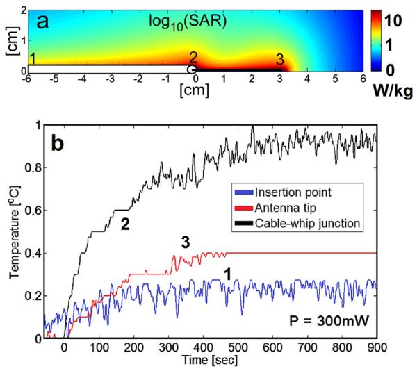
FIG. 2.
a: Computed relative SAR (logarithmic scale) annotated to show temperature probe placement in the safety studies. b: Temperature rise during a 15 min radiofrequency exposure at a continuous input power of 300 mW, as measured at the insertion point (blue, 1), cable-whip junction (black, 2), and tip (red, 3). [Color figure can be viewed in the online issue, which is available at wileyonlinelibrary.com.]
A 7T biocompatible nitinol loopless antenna was fabricated for in vivo use from an obsolete 0.76 mm diameter Intercept 1.5T guide wire (MRI Interventions Inc., Memphis, TN) by cutting the distal coaxial cable to 3l/4 (54 cm), and the whip to 6.1 cm.
RF Safety Testing
RF safety was tested with the loopless antenna inside a 20 cm diameter, 20 cm long cylindrical saline phantom prepared with 15 gL−1 polyacrylic acid to inhibit convection (higher viscosity but the same thermal conductivity as water). The electrical properties were matched to those simulated, by reducing the salt concentration to 0.8 gL−1 to provide an antenna load equivalent to the 3.5 gL−1 saline. A constant amplitude forward RF power of 300 mW at 298 MHz and 100% duty cycle was applied to the device, and the temperature was monitored with fiber-optic temperature sensors (Neoptix, Inc., Quebec, Canada) contacting the antenna at locations determined from the simulations to have the highest SAR (the cablewhip junction, tip, and insertion point). The temperature was sampled at 1 Hz for at least 1 min with the RF power turned off and 15 min with the RF power on.
MRI Performance
The performance of the 5 Gaussian composite pulse and a conventional selective excitation pulse at 7T were compared in the cylindrical phantom filled with 0.5 gL−1 CuSO4-doped saline with the same loading as in the RF safety tests, and in a kiwi fruit. The RF power loss between the power amplifier and the coil interface was measured at 50%. Average power at the device was set to levels that ensured RF heating ≤2 °C as determined from the RF safety experiments. Spin-lattice relaxation (T1)-weighted two-dimensional (2D) fast-field echo (FFE) sequences were used (repetition time [TR] = 200 ms; echo time [TE] = 15 ms; FOV = 5 × 5 cm2; voxel size = 100 × 100 μm2; nominal slice thickness, 3.2 mm). To verify slice selection, an eight-step phase-coding gradient was added to the slice selection gradient waveform with 0.8-mm resolution (3D FFE; FOV = 5 × 5 × 0.64 cm3). The applied forward power (PF) was determined from the incident power (Pi) at the proximal end of the antenna cable by means of:
| [2] |
where Γ is the reflection coefficient measured using a network analyzer. A “20% useable” imaging FOV diameter was defined as that corresponding to 20% of the maximum received signal intensity outside the antenna. This was determined for forward peak pulse powers of 1–16 W with all other imaging parameters held constant.
Large FOV MRI was tested with the antenna in a large pomelo fruit (multi-echo T1-weighted FFE; TR = 200 ms; TEs =7, 17, 27, 37 ms; FOV = 12 × 12 cm2; voxel size, 0.5 × 0.5 mm2; peak PF = 58 W; average PF = 359 mW; 2 averages; duration, 97 s). An inhomogeneously broadened T2 (T2*) image was calculated from the exponentially fitted magnitude images acquired at the different TEs. Low- and high-resolution MRI was also performed on human iliac artery specimens obtained from our institution’s autopsy service. Specimens were immersed in a (3.5 gL−1) saline bath, the loopless antenna inserted in the lumen, and T1-weighted FFE sequences applied. Low-resolution coronal scout MRI (TR/TE = 200/15 ms; scan time = 49 s; FOV = 16 × 6 cm2, voxel size = 250 × 94 μm2; average PF, 99 mW was followed by rapid axial MRI of a region-of-interest (ROI; TR/TE = 100/10 ms; scan time = 10 s; FOV = 2 × 2 cm2; voxel size = 100 × 100 μm2; radial readout with 50% density; average PF = 50 mW), and/or high-resolution MRI (TR/TE = 150/22 ms; scan time 151 s; FOV = 5 × 5 cm2; voxel size = 50 × 50 μm2; average PF = 33 mW). Nominal slice thickness was 3.2 mm.
In vivo studies, approved by our Institutional Animal Care and Use Committee, were performed on healthy sedated New Zealand rabbits. The nitinol loopless antenna was inserted into the ascending aorta by means of the femoral artery and a 5-French introducer, under X-ray guidance. The animal was moved to the 7T scanner and coronal scout MRI was performed using the transmit/receive antenna, followed by axial 2D FFE MRI with an 8 W applied forward peak power at the antenna input. Images were cardiac-gated with TR at the heart rate. Larger FOV axial MRI was performed (TR = 0.2–0.3 s; TE = 6 ms; FOV = 6–9 cm; voxel size = 300–500 μm; 3–4 mm slices; scan duration = 1–2 min, PF = 8–32 W), followed by higher resolution 100–200 μm MRI (TR = 0.35–0.46 s; TE = 7–10 ms; FOV = 3 cm; scan duration = 140–152 s; PF = 8 W).
RESULTS
Simulations
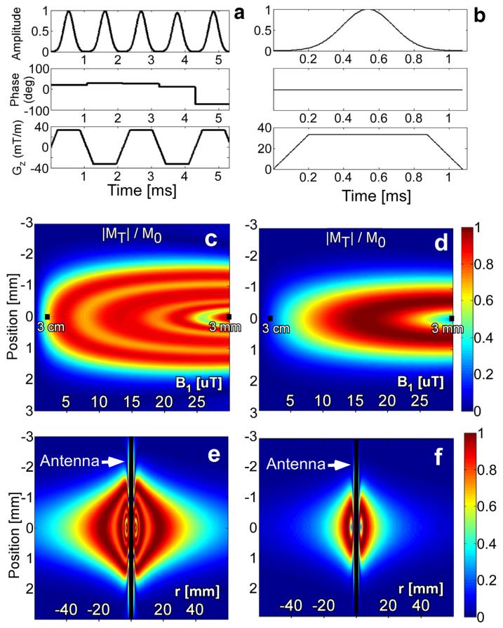
The computed amplitude, phase, and gradient waveforms of the 5 Gaussian composite pulse are shown in Figure 1a. With a peak power of 4 W, the B1 amplitude falls from 8.0 μT at 1 cm to 2.0 μT at 3 cm. This pulse excites ≥50% of M0 for 1.5 ≤B1≤32 μT corresponding to a 6.2 cm diameter excitation disk (Fig. 1e). By comparison, a single Gaussian-modulated pulse excites ≥50% of M0 over 5.6≤B1≤27.0 μT, yielding only a 2.7 cm diameter 50% excitation disk (Fig. 1f). Increasing the applied power of the single Gaussian pulse does extend its FOV but produces dark rings at multiples of 180° flip angle (FA) close to the antenna where receiver sensitivity is greatest. Thus, the lower B1 excitation threshold of the composite pulse more than doubles the diameter (or quadruples the area) of the MRI excitation volume compared with applying a single pulse using the loopless antenna transmitter.
FIG. 1.
Along the first row, (a) B1 amplitude, B1 phase, and gradient amplitude waveforms for the 5 Gaussian composite pulse, and (b) a conventional single-lobe Gaussian pulse are shown. The second row shows the transverse magnetization at the end of (c) the 5 Gaussian composite, and (d) a single Gaussian pulse for 0≤B1≤30 μT and T2 = 30 ms. The B1 at 3 mm and at 3 cm from the antenna junction are annotated. The third row shows the transverse magnetization as a function of axial position (r) for the (e) 5 Gaussian and (f) single Gaussian pulses ±6 cm from the antenna. The applied peak pulse power was 4 W throughout.
Signal loss with T2 = 30 ms at the end of the 5 Gaussian composite pulse is 10% (Fig. 1c) versus 2% for the single Gaussian pulse (Fig. 1d). Although an 11 Gaussian composite (not shown) excites more uniformly than the 5 Gaussian pulse, its T2 losses increase to 19%. We therefore chose the 5.4 ms long 5 Gaussian pulse as an acceptable compromise between uniformity and T2 loss. Its full-width half-maximum slice thickness is 3.2 mm on-resonance at a radial distance r = 7 mm from the antenna, decreasing to 2.9 mm and 2.0 mm at r = 1 and 3 cm, respectively. Off-resonance (ΔB0 = −200/+350 Hz) slice thickness is 2.3 mm at r = 1 cm and 2.0 mm at r = 3 cm. As usual, slice thickness can be adjusted by changing the gradient amplitude or pulse length. Here, hardware constrained the maximum gradient strength to 33 mT/m, but thinner slices (<3 mm) could be obtained by increasing the length of subpulses.
RF Safety Testing
The numerically computed SAR distribution and temperature probe placements are shown in Figure 2a. The temperature rise at an applied average PF = 300 mW did not exceed 1 °C during 15 min of continuous RF excitation (Fig. 2b). The highest temperature rise occurred at the cable-whip junction with the tip and insertion points heating less, consistent with the electromagnetic simulations (Fig. 2a). Thus, operation with ≤1 °C local temperature rise is achievable with average power levels of <300 mW. This translates to minimum TRs of 8.2, 16.5, and 66 ms with peak applied RF pulse PF levels of 2, 4, and 16 W, respectively.
MRI Performance
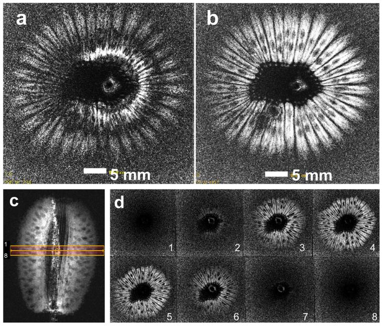
Axial images from a kiwi fruit with the transmit/receive loopless antenna using a two-lobe conventional sinc pulse and the 5 Gaussian composite pulse are shown in Figure 3. With the sinc pulse, the image is degraded by dark ring artifacts at 180° FA multiples (Fig. 3a) that are not present in the image acquired with the 5 Gaussian pulse (Fig. 3b). The coronal image in Figure 3c is annotated to show the axial 0.8-mm slices of the 3D FFE experiment to demonstrate the spatial selectivity of the composite pulse. As shown in Figure 3d, only the middle four slices of the 3D set exhibit signal, consistent with the nominal 3.2 mm slice thickness.
FIG. 3.
Axial images acquired with (a) a transmit/receive loopless antenna using a conventional sinc-modulated pulse, and (b) using the 5 Gaussian composite pulse (T1-weighted 2D FFE; TR/TE=200/15 ms; FOV=5 × 5 cm2 ; voxel size=100 × 100 μm2; nominal slice thickness, 3.2 mm). c: Coronal image annotated with orange grid to show the planning of the 3D experiment to demonstrate slice selectivity (T1-weighted 2D FFE; TR/TE=200/15 ms; FOV=5 × 5 cm2 ; voxel size=100 × 100 μm2; nominal slice thickness, 3.2 mm). d: Axial 0.8 mm thick images from the 3D experiment show signal in four slices consistent with the 3.2-mm slice thickness (3D FFE; FOV=5 × 5 × 0.64 cm3). [Color figure can be viewed in the online issue, which is available at wileyonlinelibrary.com.]
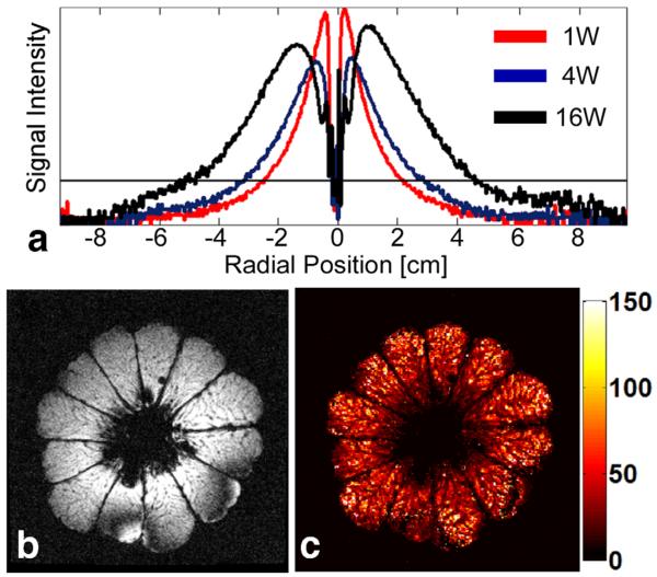
Without a global view provided by an external coil, to select an image plane, one must first find the antenna in a large FOV scan. Figure 4a shows “20% useable” FOV diameters of 48, 62, and 98 mm at peak PF’s of 1, 4, and 16 W, respectively. At 58 W, an entire 10.5 cm pomelo is excited (Fig. 4b). The dark lines in the computed T2* image (Fig. 4c) are membranes separating juice compartments whose uniform depiction demonstrates that the composite pulse is robust to T2 losses across the entire FOV.
FIG. 4.
a: Signal intensity profiles acquired inside a homogeneous phantom with identical imaging parameters at 1, 4, and 16 W (red, blue, and black, respectively) of applied peak forward power (PF) are shown. The horizontal line indicates the thresholding level for determining the “20% useable” imaging FOV, which is 48.4, 61.5, and 98.3 mm for 1, 4, and 16 W of applied peak PF, respectively. b: Large FOV axial (TE = 7 ms) 2D image acquired inside a pomelo fruit. c: T2* map calculated using the magnitude images acquired at different TEs (multi-echo T1-weighted FFE; TR 200 ms; echo-times TE = 7, 17, 27, 37 ms; FOV 12 12 cm2; voxel size, 0.5 × 0.5 mm2; peak applied PF, 58 W; average PF, 359 mW; two averages; duration, 97 s; color scale in ms at right). [Color figure can be viewed in the online issue, which is available at wileyonlinelibrary.com.]
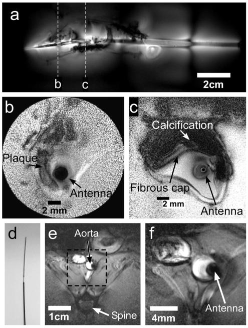
For in vitro and in vivo intravascular studies, the global view is afforded by a fast, low-resolution, coronal scan that is brightest around the antenna with an FOV that again increases with PF (Fig. 5a). After locating an ROI on the coronal scan, rapid 100 μm axial MRI (Fig. 5b) or slower (Fig. 5c) higher resolution (50 μm) MRI can be performed at reduced power levels and FOV. In vessel specimens in vitro, these show a lesion and plaque components including a fibrous cap (annotated). The signal loss in the biocompatible 3λ/4 nitinol cable used for in vivo studies (Fig. 5d) was 21% (insertion loss = 2 dB) compared with the “lossless” copper cable used in vitro. In an in vivo rabbit study using the same MRI protocol but with cardiac gating, the ~3 mm diameter aorta and anatomy is depicted at 300 μm resolution with large FOV (Fig. 5e), and at 100 μm resolution with reduced FOV MRI (Fig. 5f).
FIG. 5.
a: Large-FOV intravascular coronal scout image of a diseased human iliac vessel in a saline tank annotated to show sections imaged in parts (b) and (c) (T1-weighted FFE; TR/TE = 200/15 ms; duration = 49 s; FOV = 16 × 6 cm2; voxel size = 250 × 94 μm2). Annotated high-resolution trans-axial images through the vessel wall (b: TR/TE 100/10 ms; duration 10 s; FOV = 2 × 2 cm2; voxel size 100 × 100 μm2; radial readout with 50% density. c: TR/TE = 150/22 ms; duration = 151 s; FOV = 5 × 5 cm2; voxel size = 50 × 50 μm2). d: Photograph of the distal end of the 0.76-mm-diameter 7T biocompatible nitinol loopless antenna. e: Large-FOV in vivo axial image through the aorta of a healthy rabbit (TR/TE = 231/5.9 ms; duration = 70 s; FOV = 9 × 9 cm2; voxel size = 300 × 300 μm2; slice thickness = 4 mm; bandwidth = 154 kHz; Pi = 64 W). f: In vivo 100-μm image of the annotated region thickness 4 mm; from part (e) (TR/TE = 462/9.8 ms; duration = 140 s; FOV = 3 × 3 cm2; voxel size = 100 × 100 μm2; slice thickness = 4 mm; bandwidth = 52 kHz; Pi = 16 W).
DISCUSSION
In this work, we investigated the feasibility of 7T MRI with an internal transmit/receive loopless antenna and no external coils. RF power requirements, B1-field inhomogeneity, and local SAR are a challenge at 7T. For studies involving internal conductors and/or active MRI detectors, potential coupling with an external transmitter field and dealing with B1 variations if the conductor/detector is moved represent additional complexities. These on top of an already complicated environment and workflow make interventional MRI at 7T a daunting prospect. Nevertheless, the dramatically improved SNR, at least for the loopless antenna, offers an unprecedented high-resolution imaging opportunity that is presently not practical at lower fields (2), or even at 7T with the external detectors developed to date.
Compared with the use of internal loop coils for prostate MRI at 7T (13,14,20-22), the submillimeter dimensions possible with the loopless antenna enable targeted intravascular access under image guidance (23-25), not accessible to larger internal coils. Indeed, the 50- to 100-mm resolution achieved here in vitro and/or in vivo are smaller than the best resolution achieved to date at 7T of 0.5 × 0.5 mm2, using prostate coils with similar slice thickness (13). Yet prostate coils have already been used in humans at 7T, while the loopless antenna has so far only been used in patients at 1.5T (23), and the best resolution achieved at 1.5T was ~160 μm (1,3).
The primary limitation that we encountered in using the composite pulse was its 90° FA, which limited short-TR Ernst-angle acquisitions and SNR efficiency even while providing the best B1 performance in simulations (Fig. 1). This resulted in scan times of ~2 min for high-resolution (≤100 μm) in vivo studies using conventional cardiac-gated 2D FFE imaging. Although cardiac gating was effective in ameliorating motion artifacts, we had previously achieved 80–100 μm resolution at up to one to two frames/s in vivo at 3T using steady-state free-precession (SSFP) sequences (26). Thus, scan efficiency in future applications of the composite pulse at 7T could benefit from a reduced FA in combination with SSFP approaches.
Using the loopless antenna for both transmit and receive eliminates both coupling issues and the need for B1-shimming because the B1-field follows the probe during the procedure. Whereas this is analogous to MRI endoscopy (15), the present approach differs in that MRI endoscopy uses no slice selection and its profile is fixed. However, like MRI endoscopy, the transmit/receive antenna can be excited with a few Watts of peak RF power, and peak local heating can be kept within safe levels, even <1° C (Fig. 2), by setting input power and TR. The maximum or peak local temperature rise must be calibrated against the power delivered to the coil to ensure safe operation.
Because B1 decays rapidly with radial distance from the antenna, the use of conventional slice-selective pulses results in artifacts at 180° multiples when the antenna is used for excitation. Conversely, the use of spatially selective B1-insensitive composite RF pulses excited up to ~10 cm diameter volumes, without significant artifacts (Fig. 4). Although the excitation profile could be further optimized by increasing the number of subpulses or changing the modulation waveforms, there is a trade-off between modifications that increase pulse length versus signal loss due to T2 decay.
Decreasing the excitation FOV with conventional 7T external coils (27,28) is also challenging due to B1-inhomogeneity and SAR restrictions. Without FOV reductions, scan time may be prohibitive for sub 100 μm 7T MRI, regardless of SNR. A transmit/receive internal antenna whose FOV can be varied simply by adjusting the pulse power offers considerable versatility for interactively adjusting scan time and spatial resolution. Large-FOV, low-resolution scout MRI performed in a high-power mode can be enjoyed for locating both device and target, and guiding one to the other. After locating an ROI, the operator can switch to a low-power navigation mode, shrinking the imaging FOV. Not only does lower power permit shorter TRs, but scan time can be further reduced because fewer k-space lines or phase-encoding steps are required for the smaller FOV. Finally, at a target site of intervention or suspect lesion, high-resolution MRI at an ~50 μm level is possible (Fig. 5), where the FOV could be further reduced to increase speed. At this resolution, it might be possible to measure fibrous cap thickness in vulnerable atherosclerotic lesions (29), or perhaps senile plaques in aging brain (30).
ACKNOWLEDGMENTS
We thank Shashank Hegde, Juls Meyers, and Laurie Pipitone for help with the in vivo experiments. P.A.B. has a financial relationship with MRI Interventions Inc, from whom the 1.5T biocompatible guide wire modified for 7T use was obtained.
Grant sponsor: National Institutes of Health; Grant numbers: R01 EB007829.
REFERENCES
- 1.Ocali O, Atalar E. Intravascular magnetic resonance imaging using a loopless catheter antenna. Magn Reson Med. 1997;37:112–118. doi: 10.1002/mrm.1910370116. [DOI] [PubMed] [Google Scholar]
- 2.Erturk MA, El-Sharkawy AM, Bottomley PA. Interventional loopless antenna at 7 T. Magn Reson Med. 2012;68:980–988. doi: 10.1002/mrm.23280. [DOI] [PMC free article] [PubMed] [Google Scholar]
- 3.El-Sharkawy AMM, Qian D, Bottomley PA. The performance of interventional loopless MRI antennae at higher magnetic field strengths. Med Phys. 2008;35:1995–2006. doi: 10.1118/1.2905027. [DOI] [PMC free article] [PubMed] [Google Scholar]
- 4.Ibrahim TS, Lee R, Baertlein BA, Abduljalil AM, Zhu H, Robitaille PML. Effect of RF coil excitation on field inhomogeneity at ultra high fields: a field optimized TEM resonator. Magn Reson Imaging. 2001;19:1339–1347. doi: 10.1016/s0730-725x(01)00404-0. [DOI] [PubMed] [Google Scholar]
- 5.Vaughan JT, Garwood M, Collins CM, et al. 7T vs. 4T: RF power, homogeneity, and signal-to-noise comparison in head images. Magn Reson Med. 2001;46:24–30. doi: 10.1002/mrm.1156. [DOI] [PubMed] [Google Scholar]
- 6.Ibrahim TS, Lee R, Abduljalil AM, Baertlein BA, Robitaille PML. Dielectric resonances and B-1 field inhomogeneity in UHFMRI: computational analysis and experimental findings. Magn Reson Imaging. 2001;19:219–226. doi: 10.1016/s0730-725x(01)00300-9. [DOI] [PubMed] [Google Scholar]
- 7.Hoult DI. Sensitivity and power deposition in a high-field imaging experiment. J Magn Reson Imaging. 2000;12:46–67. doi: 10.1002/1522-2586(200007)12:1<46::aid-jmri6>3.0.co;2-d. [DOI] [PubMed] [Google Scholar]
- 8.Collins CM, Smith MB. Calculations of B-1 distribution, SNR, and SAR for a surface coil adjacent to an anatomically-accurate human body model. Magn Reson Med. 2001;45:692–699. doi: 10.1002/mrm.1092. [DOI] [PubMed] [Google Scholar]
- 9.Vaughan T, DelaBarre L, Snyder C, et al. 9.4T human MRI: preliminary results. Magn Reson Med. 2006;56:1274–1282. doi: 10.1002/mrm.21073. [DOI] [PMC free article] [PubMed] [Google Scholar]
- 10.Zhu YD. Parallel excitation with an array of transmit coils. Magn Reson Med. 2004;51:775–784. doi: 10.1002/mrm.20011. [DOI] [PubMed] [Google Scholar]
- 11.Katscher U, Bornert P, Leussler C, van den Brink JS. Transmit SENSE. Magn Reson Med. 2003;49:144–150. doi: 10.1002/mrm.10353. [DOI] [PubMed] [Google Scholar]
- 12.Katscher U, Bornert P, Parallel RF. transmission in MRI. NMR Biomed. 2006;19:393–400. doi: 10.1002/nbm.1049. [DOI] [PubMed] [Google Scholar]
- 13.Metzger GJ, van de Moortele PF, Akgun C, et al. Performance of external and internal coil configurations for prostate investigations at 7 T. Magn Reson Med. 2010;64:1625–1639. doi: 10.1002/mrm.22552. [DOI] [PMC free article] [PubMed] [Google Scholar]
- 14.de Castro CSA, Luttje MP, van Vulpen M, Luijten PR, van der Heide UA, Klomp DWJ. Composite slice-selective adiabatic excitation for prostate MRSI. NMR Biomed. 2013;26:436–442. doi: 10.1002/nbm.2881. [DOI] [PubMed] [Google Scholar]
- 15.Sathyanarayana S, Bottomley PA. MRI endoscopy using intrinsically localized probes. Med Phys. 2009;36:908–919. doi: 10.1118/1.3077125. [DOI] [PMC free article] [PubMed] [Google Scholar]
- 16.Moore J, Jankiewicz M, Anderson AW, Gore JC. Slice-selective excitation with B(1)(+)-insensitive composite pulses. J Magn Reson. 2012;214:200–211. doi: 10.1016/j.jmr.2011.11.006. [DOI] [PMC free article] [PubMed] [Google Scholar]
- 17.Ouwerkerk R, Weiss RG, Bottomley PA. Measuring human cardiac tissue sodium concentrations using surface coils, adiabatic excitation, and twisted projection imaging with minimal T-2 losses. J Magn Reson Imaging. 2005;21:546–555. doi: 10.1002/jmri.20322. [DOI] [PubMed] [Google Scholar]
- 18.Wang G, El-Sharkawy AM, Edelstein WA, Schar M, Bottomley PA. Measuring T(2) and T(1), and imaging T(2) without spin echoes. J Magn Reson. 2012;214:273–280. doi: 10.1016/j.jmr.2011.11.016. [DOI] [PMC free article] [PubMed] [Google Scholar]
- 19.Biasiolli L, Lindsay AC, Choudhury RP, Robson MD. In-vivo T2 mapping of atherosclerotic plaques in carotid arteries; Poster Presentation of the 15th Scientific Sessions of ACMR; Orlando, FL. 2012; abstract 134. [Google Scholar]
- 20.Klomp DW, Scheenen TW, Arteaga CS, van Asten J, Boer VO, Luijten PR. Detection of fully refocused polyamine spins in prostate cancer at 7 T. NMR Biomed. 2011;24:299–306. doi: 10.1002/nbm.1592. [DOI] [PubMed] [Google Scholar]
- 21.van den Bergen B, Klomp DWJ, Raaijmakers AJE, de Castro CA, Boer VO, Kroeze H, Luijten PR, Lagendijk JJW, van den Berg CAT. Uniform prostate imaging and spectroscopy at 7 T: comparison between a microstrip array and an endorectal coil. NMR Biomed. 2011;24:358–365. doi: 10.1002/nbm.1599. [DOI] [PubMed] [Google Scholar]
- 22.Arteaga de Castro CS, van den Bergen B, Luijten PR, van der Heide UA, van Vulpen M, Klomp DW. Improving SNR and B1 transmit field for an endorectal coil in 7 T MRI and MRS of prostate cancer. Magn Reson Med. 2012;68:311–318. doi: 10.1002/mrm.23200. [DOI] [PubMed] [Google Scholar]
- 23.Dick AJ, Raman VK, Raval AN, et al. Invasive human magnetic resonance imaging: feasibility during revascularization in a combined XMR suite. Catheter Cardiovasc Interv. 2005;64:265–274. doi: 10.1002/ccd.20302. [DOI] [PMC free article] [PubMed] [Google Scholar]
- 24.Yang X, Bolster BD, Jr, Kraitchman DL, Atalar E. Intravascular MR-monitored balloon angioplasty: an in vivo feasibility study. J Vasc Interv Radiol. 1998;9:953–959. doi: 10.1016/s1051-0443(98)70429-4. [DOI] [PubMed] [Google Scholar]
- 25.Arepally A, Karmarkar PV, Weiss C, Rodriguez ER, Lederman RJ, Atalar E. Magnetic resonance image-guided trans-septal puncture in a swine heart. J Magn Reson Imaging. 2005;21:463–467. doi: 10.1002/jmri.20262. [DOI] [PubMed] [Google Scholar]
- 26.Sathyanarayana S, Schar M, Kraitchman DL, Bottomley PA. Towards real-time intravascular endoscopic magnetic resonance imaging. JACC Cardiovasc Imaging. 2010;3:1158–1165. doi: 10.1016/j.jcmg.2010.08.014. [DOI] [PMC free article] [PubMed] [Google Scholar]
- 27.Wilm BJ, Svensson J, Henning A, Pruessmann KP, Boesiger P, Kollias SS. Reduced field-of-view MRI using outer volume suppression for spinal cord diffusion imaging. Magn Reson Med. 2007;57:625–630. doi: 10.1002/mrm.21167. [DOI] [PubMed] [Google Scholar]
- 28.Hargreaves BA, Cunningham CH, Nishimura DG, Conolly SM. Variable-rate selective excitation for rapid MRI sequences. Magn Reson Med. 2004;52:590–597. doi: 10.1002/mrm.20168. [DOI] [PubMed] [Google Scholar]
- 29.Tanaka A, Imanishi T, Kitabata H, et al. Morphology of exertion-triggered plaque rupture in patients with acute coronary syndrome: an optical coherence tomography study. Circulation. 2008;118:2368–2373. doi: 10.1161/CIRCULATIONAHA.108.782540. [DOI] [PubMed] [Google Scholar]
- 30.Cruz L, Urbanc B, Buldyrev SV, Christie R, GomezIsla T, Havlin S, McNamara M, Stanley HE, Hyman BT. Aggregation and disaggregation of senile plaques in Alzheimer disease. Proc Natl Acad Sci U S A. 1997;94:7612–7616. doi: 10.1073/pnas.94.14.7612. [DOI] [PMC free article] [PubMed] [Google Scholar]


