Abstract
Purpose
Component orientations and positions in total hip arthroplasty (THA) are important parameters in restoring hip function. However, measurements using plain radiographs and 2D computed tomography (CT) slices are affected by patient position during imaging. This study used 3D CT to determine whether contemporary THA restores native hip geometry.
Methods
Fourteen patients with unilateral THA underwent CT scan for 3D hip reconstruction. Hip models of the nonoperated side were mirrored with the implanted side to quantify the differences in hip geometry between sides.
Results
The study demonstrated that combined hip anteversion (sum of acetabular and femoral anteversion) and vertical hip offset significantly increased by 25.3° ± 29.3° (range, −25.7° to 55.9°, p = 0.003) and 4.1 ± 4.7 mm (range, −7.1 to 9.8 mm, p = 0.009) in THAs.
Conclusions
These data suggest that hip anatomy is not fully restored following THA compared with the contralateral native hip.
Keywords: Total hip arthroplasty, Component orientation, Component position, Computed tomography
Introduction
Total hip arthroplasty (THA) is a highly successful surgical treatment to restore hip function for patients with severe hip arthritis, avascular necrosis and other hip diseases [1]. One of the important goals of THA is to restore the hip joint adversely affected by the degenerative arthritic process. Thus, positions and orientations of the acetabular cup and femoral components can directly affect loading conditions of the reconstructed hip articular surfaces and the behaviuor of surrounding force-bearing structures. Malposition or misalignment of implanted components are associated with adverse clinical outcomes, such as hip impingement [2] and dislocation [3], increased liner wear and fracture, periprosthetic osteolysis [4], edge loading [5] and increased metal ion load in the blood [6]. Restoration of hip anatomy in position and orientation, including native anteversion, location of the femoral head centre and leg length is critical in optimising hip function [7, 8].
Previous studies investigated acetabular cup orientation and position following THA using plain radiographs and 2D) computed tomography (CT) images [9–11]. Lewinnek et al. suggested a safe zone of cup orientation to reduce the dislocation rate [9]. Superolateral relocation of the acetabular cup was found to cause a significant increase in hip joint force [10] and was associated with increased acetabular failure [11]. Recently, investigators proposed optimising combined anteversion [12] (sum of acetabular and femoral anteversion) to reduce THA dislocation rates. Further, femoral offset differences have been implicated in unsatisfactory clinical results following THA [13]. However, whether contemporary THA restores the 3D orientation and position of native hip geometry remains largely unknown, as no data has been reported on the comparison of 3D orientations and positions of both the femur and acetabulum between THA and the contralateral, nonimplanted hip.
The purpose of this study was therefore to determine, using CT imaging and 3D modeling techniques, whether contemporary THA restores native hip anatomy by quantifying differences in orientations and positions between the implanted hip and contralateral nonimplanted native hip in patients with unilateral THA.
Materials and methods
Patients
Fourteen patients with hip osteoarthritis (OA) (seven men and seven women) who underwent unilateral THA participated in this study. All patients received cementless unilateral THA with Zimmer Trilogy acetabular cup, longevity highly cross-linked polyethylene, ML taper and cobalt–chromium (CoCr) femoral head (Zimmer, Warsaw, IN, USA). Acetabular cup and femoral head sizes ranged from 50 to 56 mm and 32 to 36 mm, respectively. The study was approved by the institution’s Internal Review Board, and each patient provided written informed consent prior to participation. Patient median age was 58.5 (± 7.0, range 47‒70) years. Median body height and weight were 168.9 cm (± 8.4, range 157.5‒185.4) and 86.3 kg (± 14.3, range 59.9‒103.0), with median body mass index (BMI) of 29.4 (± 3.6, range 20.7‒31.8). Median follow-up was 16.5 months (± 13.3, range 6‒39) from surgery. No patient had a history of dislocation, subluxation or any surgical complication.
CT-based 3D modeling and mirroring
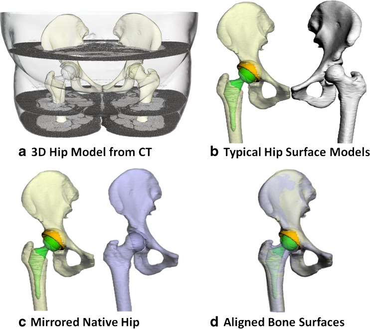
In accordance with previously published and validated study protocol [14], each patient received a CT scan (Sensation 64, Siemens, Germany) from the fifth lumbar vertebra to the mid-femur for creation of surface models of the acetabular cup, femoral stem, femur and hip bone (formed by ilium, ischium and pubis) (Fig. 1a). For comparison of anatomical measures between THA and native hip (Fig. 1b), surface models of the contralateral native hip bone and the femur were mirrored with respect to the sagittal plane (Fig. 1c). The mirrored models were then aligned with the hip bone and the femur of the implanted side (Fig. 1d) using the method of iterative closest points [15]. A 3D deviation analysis on mirrored models and implanted side showed that the average ± standard deviation (SD) of distances in between were 0.98 ± 0.24 mm for the hip bone and 0.69 ± 0.26 mm for the proximal femur.
Fig. 1.
a Three-dimensional models of the hip bone, femur, acetabular cup and femoral stem reconstructed from computed tomography (CT) scan data. b Models were split into implanted and native groups. c The contralateral native hip model was mirrored with respect to the sagittal plane. d The mirrored hipbone and femur were then best aligned with the implanted hipbone and the remaining femur of the implanted side
Acetabular and femoral orientation/position measurements
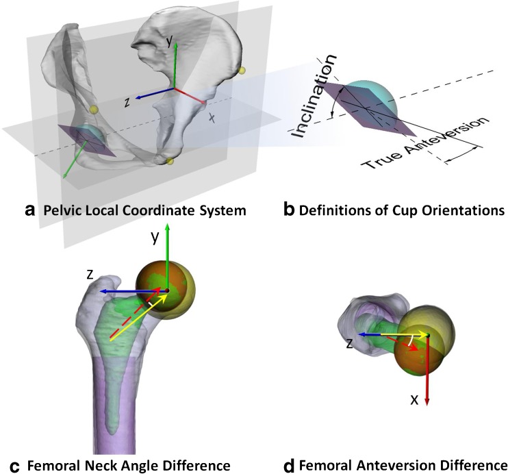
The frontal pelvic plane [9] was considered as the y–z plane of the local pelvic coordinate system, with the z axis parallel to the medial and lateral axis (Fig. 2a). To measure acetabular cup orientations of aligned native and implanted hips, 30 points evenly distributed on the rim of the acetabular cup were digitised and fitted with a 3D plane to determine cup-opening plane of each bony and implant cup. Acetabular anatomical anteversion was defined as a transverse plane angle between the best fitted cup-opening plane and the sagittal plane (Fig. 2b) [16]. Acetabular anatomical inclination was defined as a coronal plane angle between cup opening plane and transverse plane (Fig. 2b) [16]. Femoral neck axis was determined by linking the centroid of a cross section at the mid-femoral-neck level to the femoral head centre. The neck axis was projected onto the transverse and coronal planes to measure differences in femoral anteversion and shaft-neck angle between THA and native hips (Fig. 2b and c). Differences in cup anteversion and inclination between THA and native hip were also calculated.
Fig. 2.
a Origin of local pelvic coordinate system located at the midpoint of ASISs. The x axis is perpendicular to the frontal pelvic plane; x, y and z axes point anteriorly, superiorly and to the right. b Definitions of cup inclination and true (anatomical) anteversion. c Origin of femoral coordinate system at the centre of the femoral head. Y axis is parallel to the long axis of the best-fit cylinder to the femoral shaft; difference in femoral neck angles was quantified. The red dashed and yellow lines indicate the stem and native femoral neck axis, respectively. d X axis is perpendicular to the plane formed by the femoral long axis and origin; difference in femoral anteversion between implanted and native hips was measured
Hip joint centres (HJC) of the pelvis and femur were measured for both implanted and native hips. The centroid of the best fitted sphere to the horseshoe surface of the bony acetabular cup was determined as the native pelvic HJC (Fig. 2a). Femoral HJC of the native hip was defined at the centre of the femoral head (Fig. 2c). For THAs, HJCs of pelvis and femur were defined as the centroid of the best-fitted sphere to the femoral head. Projection of differences between implanted pelvic HJC location and mirrored native pelvic HJC location along the pelvic local axes were considered as local cup translations, e.g. cup lateralisation, medialisation and vertical elevation. Differences between implanted femoral HJC location and mirrored native HJC along the local femoral axes were calculated as changes in femoral anterior/posterior (A/P) offset, femoral vertical [superior/inferior (S/I)] offset and femoral horizontal [lateral/medial (L/M)] offset.
Overall changes in orientations and positions of articulation surfaces at the implanted hip were calculated by combining changes in both acetabular and femoral components with respect to the contralateral native hip. Combined anteversion, inclination and translations along A/P, S/I and L/M are reported.
Statistical analysis
Differences between native and implanted hips of each THA patient regarding cup inclination, cup anteversion, femoral anteversion, femoral-shaft-neck angle and HJC locations along anatomical axes were measured. Average, SD and range of differences between the two sides were calculated. Root mean square error across patients was also calculated for differences in positions and orientations to show the overall magnitude of the varying quantity of differences. Kolmogorov–Smirnov tests showed that the measured variables were nonnormally distributed. Wilcoxon signed rank tests were performed to test whether measured differences arose from a continuous, symmetric distribution with zero median. A level of significance was set at α = 0.05.
Results
Three-dimensional acetabular cup and femoral orientations
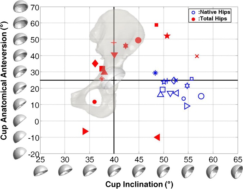
Median acetabular anatomical anteversion and inclination were 20.4° (SD = 5.7, range 9.2°‒29.4°) and 52.3° (SD = 2.7, range 48.4°‒57.6°) for native hips and 37.3° (SD = 21.0, range −10.1° to 58.7°) and 40.0° (SD = 6.7, range 34.0° to 56.8°) for THAs, respectively (Fig. 3). Cup anteversion of THA was significantly increased by 12.3° ± 18.3° (Fig. 3, p = 0.049). Significantly lower cup inclination by 10.2° ± 6.8° (p < 0.001) was found in THA relative to contralateral native hips (Table 1). Femoral anteversion of the implanted side was significantly increased by 11.4° ± 11.9° (Table 1, p = 0.003). Femoral-neck-shaft angle was increased by 1.0° ± 7.2° (Table 1, p = 0.463). For overall effects of THA on hip geometry, the combined anteversion was significantly increased by 23.5° ± 23.6° (Table 1, p = 0.003). The combined abduction was significantly increased by 9.2° ± 9.6° (Table 1, p = 0.009).
Fig. 3.
True cup anteversion and inclination of implanted (red closed markers) and nonimplanted (blue open markers) hips. Measures of both hips of the same patient are noted using markers in the same shape
Table 1.
Differences in acetabular cup orientation, femoral stem orientation and combined hip orientation in implanted hips with respect to native hips on the ten unilateral total hip arthroplasty (THA). Median, average (Avg) and standard deviation (SD) were calculated. Scratches under each column show the effects of positive and negative deviations
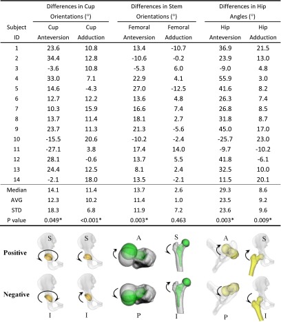
* Statistically significant
Three-dimensional acetabular cup and femoral positions
No significant differences were found in changes in cup position between THA and native hips (Table 2). Average cup translations were < 2 mm, with differences ranging from −6 to 6 mm along all anatomical directions (Table 2). On the other hand, femoral horizontal and vertical offsets were increased by 2.2 ± 4.9 mm (range −4.8 to 15.1) and 4.2 ± 5.1 mm (range −2.5 to 12.6) on average for THA (p = 0.153; 0.025, Table 2). Considering the combined differences in cup and stem positions, leg length of the THA side was significantly increased by 4.1 ± 4.7 mm (range −7.1 to 9.8, p = 0.009,) on average (Table 2).
Table 2.
Differences in acetabular cup, femoral stem and combined hip positions in implanted hips with respect to native hips on the ten unilateral total hip arthroplasty (THA) patients. Median, average (Avg) and standard deviation (SD) were calculated. Scratches under each column showed the effects of positive and negative deviations
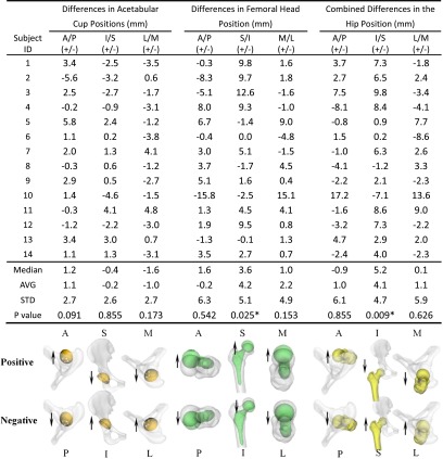
A/P anterior/posterior, M/L medial/lateral, S/I superior/inferior
* Statistically significant
Discussion
Optimal component orientation [4], femoral offset [13] and restoration of leg length [17] are factors associated with satisfactory clinical outcomes in patients with THA. However, commonly used measurements based on plain radiographs and 2D CT slices reported in previous studies are affected by hip rotation and pelvic tilt during imaging [18]. This study is one of the first to quantify differences in orientations and positions between implanted and nonimplanted hips of patients with unilateral THA using accurate and validated 3D CT-based modeling techniques. The results demonstrate a significant increase in combined hip anteversion and vertical femoral offset of THAs compared with contralateral native hips, suggesting that native hip biomechanical parameters of orientations and positions are not fully restored following THA.
This study used 3D CT-based modeling technique to reconstruct patient-specific bony models of the hip and built an anatomical coordinate system of the hip using positions of bony landmarks to consistently quantify differences in orientations and positions between implanted and nonimplanted hips of the same THA patient. Commonly reported measurements using anteroposterior radiographs of the pelvis could underestimate horizontal femoral offset [19]. Techniques using 2D CT slices may be difficult in selecting appropriate slice location and reproducible anatomical landmarks [18]. Furthermore, measuring component orientations and positions using plain radiographs and 2D CT slices can be affected by hip rotation and pelvic tilt while imaging [20]. The 3D CT modeling and mirroring technique used in this study is not affected by hip rotation and pelvic tilt during imaging. Mirroring and surface registration techniques have the capacity to quantify local differences between the geometry of two sides while avoiding the potential effects of sacroiliac joint motion and patient positions. Thus, the 3D CT modeling and mirroring technique has the capacity to accurately evaluate asymmetry between the two sides.
Reikeras and Gunderson [21] used 2D CT-slice-based measurements to examine whether the components version falls within their predefined “target zone” (femoral anteversion of 10°‒30°, acetabular anteversion of 10°–30° and a global combined anteversion of 25°‒55°) in a prospective study. Only 69 % of the of femoral components version, 58 % of the acetabular components version and 60 % of combined components version were within the target zone, but with a wide range of −18° to 101° in the combined version. Recent studies compared the reported postoperative femoral anteversion with the pre-operative values using 2D CT slices [22] and a mean difference of 8.1° ± 7.4° of increased femoral anteversion (range −11° to 22°) after THA. Suh et al. [23] also found that the femoral stem was placed in an increased anteversion of 3.8° ± 2.6° using 2D CT slice-based measurements. In our study, THA had 12.3° (range −27.1° to 34.4°) more cup anteversion and 11.4° (range −10.6° to 27°) more femoral anteversion. Changes in component orientations showed similar trends as previous literatures However, the relatively larger differences in this study may be due to the effects of accuracy of different measurement techniques. This study further revealed a 23.5° (range −25.7° to 55.9°) more combined anteversion on average in THAs than the contralateral native hips. As the change of combined anteversion is directly associated with impingement-free range of motion, the combined difference in orientations suggest that patients would have to internally rotate the hip by 23.8° and adduct by 8.2° on average to offset the differences, which might increase the probability of impingement.
Silva et al. [24] reported an average of 1.0-mm cup medialisation (range, 6.2 mm of medialisation to 5.5 mm of lateralisation) using plain radiographs. In our study, a similar amount, 1.0 mm, of medial translation on average (range, 3.8–4.8 mm of lateralisation) was found in the THA cup. As for the position of the femoral stem, Silva et al. [24] reported an average increase of 5.2 mm (range, −4.7 to 19.8 mm) in femoral horizontal offset following THA. Girard et al. [12] found an average 5.1 mm (range, −2.8 to 11.6 mm) increase following THA. This is consistent with a similar increase in femoral horizontal offset with a wide variation in THA found in our study, with an average difference of 2.2 mm (range, −4.8 to 15.1 mm) in femoral horizontal offset. Girard et al. [12] found a 2.6-mm increase in leg length following THA; Silva et al. [24] found a 5-mm increase on average, with a maximum of 12 mm. Results of this study showed that the average leg lengthening was 4.1 ± 4.7 mm (range, −7.1 to 9.8) in the THA side. Due to the use of 3D CT modeling and mirroring, this study further quantified the location of lengthening with −0.2 mm (range, −4.6 to 4.1) vertical elevation of the cup and 4.2 mm (range, −2.5 to 12.6 mm) femoral component on average. Thus, the significant leg lengthening in THAs could be attributed to the significant increase in femoral vertical offset.
The results of our study need to be interpreted in light of several limitations. Firstly, we only investigated patients using a single THA system. The uncemented femoral implants in this study tend to follow the normal anatomy of the proximal femur, limiting adjustability over stem orientation [25]. Secondly, the intended component positions of individual patients might be different. However, in all cases, the surgeon’s intended position would be within the “safe zone”, as this is an important surgical goal of THA. Furthermore, there was no case of abnormal bone anatomy, such as hip dysplasia, which would significantly alter the intended position due to acetabular or femoral bone morphology or bone stock. Thirdly, surface models of the hip were constructed while patients were scanned in the supine position. The static posture of the pelvis might be different from the standing position due to motion of the sacroiliac joint in response to gravity and might slightly affect the orientation of the pelvic coordinate system. However, since we considered the hip bone independently, data are not affected by patient positions. Finally, there was a relative small number of patients in this study due to radiation exposure concerns with CT. Despite this, statistically significant differences in combined anteversion and femoral vertical offset were observed.
In conclusion, this is the first reported study using 3D CT modeling and mirroring technique to evaluate whether THA restored the 3D native anatomy by quantifying THA differences in positions and orientations with respect to the contralateral hip in unilateral THA patients. The study demonstrated that combined hip anteversion significantly increased, up to 23.3° (23.6°), in THA. The significant leg lengthening in THA mainly came from changes in vertical offset of the femoral component. These data suggest that native hip biomechanical parameters of orientation and position are not fully restored following THA. Further studies are required to investigate the correlation between restoration of hip biomechanical geometry and in vivo functional kinematic outcomes in THA patients.
Acknowledgments
Conflict of interest disclosure
None.
References
- 1.Harris WH, Sledge CB. Total hip and total knee replacement (2) N Engl J Med. 1990;323:801–807. doi: 10.1056/NEJM199009203231206. [DOI] [PubMed] [Google Scholar]
- 2.Renkawitz T, Haimerl M, Dohmen L, et al. The association between femoral tilt and impingement-free range-of-motion in total hip arthroplasty. BMC Musculoskelet Disord. 2012;13:65. doi: 10.1186/1471-2474-13-65. [DOI] [PMC free article] [PubMed] [Google Scholar]
- 3.Barrack RL. Dislocation after total hip arthroplasty: implant design and orientation. J Am Acad Orthop Surg. 2003;11:89–99. doi: 10.5435/00124635-200303000-00003. [DOI] [PubMed] [Google Scholar]
- 4.Kennedy JG, Rogers WB, Soffe KE, et al. Effect of acetabular component orientation on recurrent dislocation, pelvic osteolysis, polyethylene wear, and component migration. J Arthroplasty. 1998;13:530–534. doi: 10.1016/S0883-5403(98)90052-3. [DOI] [PubMed] [Google Scholar]
- 5.Kwon YM, Mellon SJ, Monk P. In vivo evaluation of edge-loading in metal-on-metal hip resurfacing patients with pseudotumours. Bone Joint Res. 2012;1:42–49. doi: 10.1302/2046-3758.14.2000019. [DOI] [PMC free article] [PubMed] [Google Scholar]
- 6.Harris WH. Edge loading has a paradoxical effect on wear in metal-on-polyethylene total hip arthroplasties. Clin Orthop Relat Res. 2012;470:3077–3082. doi: 10.1007/s11999-012-2330-7. [DOI] [PMC free article] [PubMed] [Google Scholar]
- 7.Patel AB, Wagle RR, Usrey MM. Guidelines for implant placement to minimize impingement during activities of daily living after total hip arthroplasty. J Arthroplasty. 2010;25:1275–1281. doi: 10.1016/j.arth.2009.10.007. [DOI] [PubMed] [Google Scholar]
- 8.Hill JC, Archbold HA, Diamond OJ, et al. Using a calliper to restore the centre of the femoral head during total hip replacement. J Bone Joint Surg Br Vol. 2012;94:1468–1474. doi: 10.1302/0301-620X.94B11.29144. [DOI] [PubMed] [Google Scholar]
- 9.Lewinnek GE, Lewis JL, Tarr R, et al. Dislocations after total hip-replacement arthroplasties. J Bone Joint Surg Am. 1978;60:217–220. [PubMed] [Google Scholar]
- 10.Doehring TC, Rubash HE, Shelley FJ, et al. Effect of superior and superolateral relocations of the hip center on hip joint forces. An experimental and analytical analysis. J Arthroplasty. 1996;11:693–703. doi: 10.1016/S0883-5403(96)80008-8. [DOI] [PubMed] [Google Scholar]
- 11.Yoder SA, Brand RA, Pedersen DR et al. (1988) Total hip acetabular component position affects component loosening rates. Clin Orthop Relat Res:79–87 [PubMed]
- 12.Girard J, Lavigne M, Vendittoli PA, et al. Biomechanical reconstruction of the hip: a randomised study comparing total hip resurfacing and total hip arthroplasty. J Bone Joint Surg Br Vol. 2006;88:721–726. doi: 10.1302/0301-620X.88B6.17447. [DOI] [PubMed] [Google Scholar]
- 13.Liebs TR, Nasser L, Herzberg W, et al. The influence of femoral offset on health-related quality of life after total hip replacement. Bone Joint J. 2014;96:36–42. doi: 10.1302/0301-620X.96B1.31530. [DOI] [PubMed] [Google Scholar]
- 14.Tsai TY, Li JS, Wang S, et al. A novel dual fluoroscopic imaging method for determination of THA kinematics: in-vitro and in-vivo study. J Biomech. 2013;46:1300–1304. doi: 10.1016/j.jbiomech.2013.02.010. [DOI] [PubMed] [Google Scholar]
- 15.Besl PJ, McKay ND. A method for registration of 3-D shapes. IEEE Trans Pattern Anal Mach Intell. 1992;14:239–256. doi: 10.1109/34.121791. [DOI] [Google Scholar]
- 16.Murray DW. The definition and measurement of acetabular orientation. J Bone Joint Surg Br Vol. 1993;75:228–232. doi: 10.1302/0301-620X.75B2.8444942. [DOI] [PubMed] [Google Scholar]
- 17.Lecerf G, Fessy MH, Philippot R, et al. Femoral offset: anatomical concept, definition, assessment, implications for preoperative templating and hip arthroplasty. Orthop Traumatol Surg Res. 2009;95:210–219. doi: 10.1016/j.otsr.2009.03.010. [DOI] [PubMed] [Google Scholar]
- 18.Craiovan B, Renkawitz T, Weber M, et al. Is the acetabular cup orientation after total hip arthroplasty on a two dimension or three dimension model accurate? Int Orthop. 2014 doi: 10.1007/s00264-014-2336-8. [DOI] [PubMed] [Google Scholar]
- 19.Merle C, Waldstein W, Pegg E, et al. Femoral offset is underestimated on anteroposterior radiographs of the pelvis but accurately assessed on anteroposterior radiographs of the hip. J Bone Joint Surg Br Vol. 2012;94:477–482. doi: 10.1302/0301-620X.94B4.28067. [DOI] [PubMed] [Google Scholar]
- 20.Fujishiro T, Hayashi S, Kanzaki N, et al. Computed tomographic measurement of acetabular and femoral component version in total hip arthroplasty. Int Orthop. 2014 doi: 10.1007/s00264-013-2264-z. [DOI] [PMC free article] [PubMed] [Google Scholar]
- 21.Reikeras O, Gunderson RB. Components anteversion in primary cementless THA using straight stem and hemispherical cup: a prospective study in 91 hips using CT-scan measurements. Orthop Traumatol Surg Res. 2011;97:615–621. doi: 10.1016/j.otsr.2011.02.014. [DOI] [PubMed] [Google Scholar]
- 22.Emerson RH., Jr Increased anteversion of press-fit femoral stems compared with anatomic femur. Clin Orthop Relat Res. 2012;470:477–481. doi: 10.1007/s11999-011-1993-9. [DOI] [PMC free article] [PubMed] [Google Scholar]
- 23.Suh KT, Kang JH, Roh HL, et al. True femoral anteversion during primary total hip arthroplasty: use of postoperative computed tomography-based sections. J Arthroplasty. 2006;21:599–605. doi: 10.1016/j.arth.2005.04.042. [DOI] [PubMed] [Google Scholar]
- 24.Silva M, Lee KH, Heisel C, et al. The biomechanical results of total hip resurfacing arthroplasty. J Bone Joint Surg Am. 2004;86-A:40–46. doi: 10.2106/00004623-200401000-00007. [DOI] [PubMed] [Google Scholar]
- 25.Dorr LD, Malik A, Dastane M, et al. Combined anteversion technique for total hip arthroplasty. Clin Orthop Relat Res. 2009;467:119–127. doi: 10.1007/s11999-008-0598-4. [DOI] [PMC free article] [PubMed] [Google Scholar]


