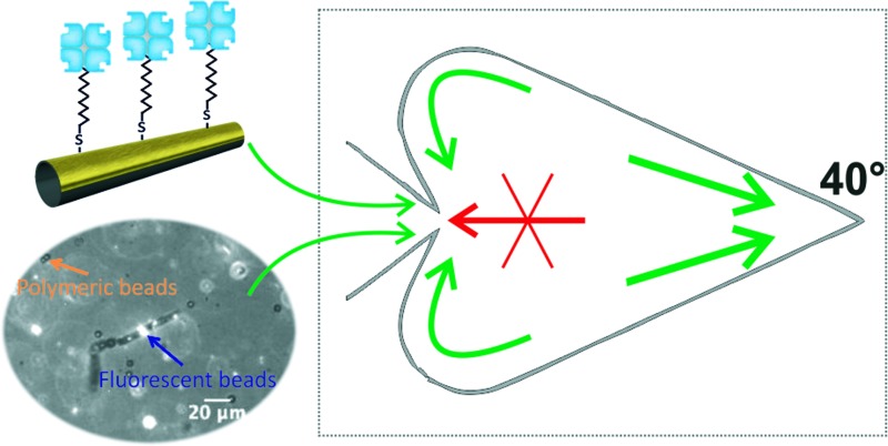
 Biofunctionalized self-propelled micromotors combined with microchips are alternative concentrating systems. No external energy source is required, facilitating integration and miniaturization.
Abstract
Sample pre-concentration is crucial to achieve high sensitivity and low detection limits in lab-on-a-chip devices. Here, we present a system in which self-propelled catalytic micromotors are biofunctionalized and trapped acting as an alternative concentrating mechanism. This system requires no external energy source, which facilitates integration and miniaturization.
During the last two decades, microfluidic systems have attracted great attention due to their fast reaction rates, portability and low reagent consumption in the performance of biological and chemical assays.1–3 Despite all these advantages, the creation of simple and efficient mechanisms to pre-concentrate and isolate specific biological components present in the sample is still necessary in order to achieve high sensitivity and low detection limits.4
Although off-chip sample pre-treatment strategies can be used to address this issue, they may introduce contamination and imply additional handling steps. Therefore, the search for on-chip concentration methods is highly desirable as it would allow the creation of fully automated portable devices that could be used for point of care diagnosis.5 So far, mechanisms to concentrate samples on-chip are focused on filtering (using porous membranes),6,7 evaporation,8 functionalized magnetic beads9,10 or electrokinetic methods.4,5 These systems can achieve high concentrating efficiencies, depending on the external mechanisms.
The functionalization of nanowire-based nanomotors was demonstrated11 and the release of cargoes using light was achieved later on.12 Also, similar nanomotors demonstrated capabilities to magnetically load cargoes13 and their magnetic guidance in microfluidic chips.14
Self-propelled catalytic micromotors have been proposed as active components for lab-on-a-chip devices.15–20 Tubular microjets are ideal architectures for combining multiple functionalities inside and outside of the micromotor chassis.21–23 In such devices, the micromotors are the vehicles used to transport specimens and mix solutions, providing an alternative to traditional external actuators, such as pumps and valves, for liquid/sample handling. Initial studies relied on micromotors pushing the load with their front part without the use of any chemical bond and, therefore, no specificity for the transport.18,19 Later on, biological recognition elements were immobilized on the outer surface of the micromotors to achieve selective load and transport of biological components such as cancer cells,24 nucleic acids,25 proteins26 and bacteria.27
The movements of the micromotor can be controlled using external mechanisms such as light,28,29 temperature,30,31 ultrasound32,33 or magnetic fields.19,34,35 Moreover, using physical boundaries of different geometries, it is possible to trap or confine them, as recently demonstrated by our group.36
Here, we combine the possibility of biofunctionalization and trapping micromotors to develop a system in which the trapping of biofunctionalized micromotors is used as an alternative concentrating mechanism for on-chip bioassays. In our system, physical boundaries with the shape of chevrons and ratchets are used to trap micromotors that are previously functionalized with streptavidin to selectively transport biotinylated components. This system allowed increasing of the number of biotinylated components in the trapping chamber acting as a concentrating device.
Our approach eliminates the need for any external mechanism to control the motion of the micromotors, since it merely relies on steric boundaries present in the micromotor environment. This can facilitate the integration of our system into a more robust and complex microfluidic platform and allows the creation of compact and portable systems.
Functionalization of micromotors
Biological recognition elements can be immobilized onto a surface using covalent or non-covalent interactions, such as physical or chemical adsorption. Covalent interactions are, however, usually preferred due to their greater stability and lower unspecific binding.37–40 Particularly, the so-called self-assembled monolayers (SAMs) of thiols on metallic substrates have been extensively used during the last two decades and are the method of our choice for the immobilization of streptavidin on the metallic surface of our micromotors.41
The micromotors used for the biofunctionalization were produced using the rolled-up technology on polymers as previously reported.42 The thin films were composed of Ti (3 nm), Fe (3 nm), Cr (3 nm) and Pt (3 nm). Once rolled up, an additional deposition step was performed to include a 10 nm thick gold layer on the outer wall of the micromotors. Using this method, we obtained micromotors of 50 μm in length and 3.75 μm in diameter, with half of their surface coated with gold.
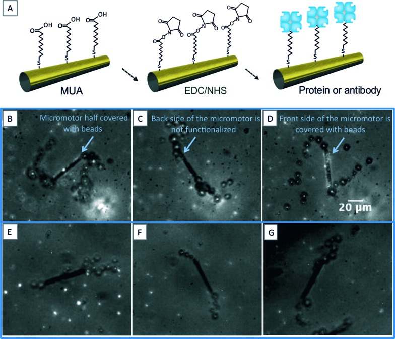
Before starting the process of functionalization, the gold layer was pretreated with oxygen plasma for 30 seconds at 50 W and an O2 flux of 5 sccm. Clean substrates were then placed in a 2 mM solution of 11-mercapto-1-undecanoic acid (MUA, Sigma cat. no. 450561) in pure ethanol overnight (12–14 h). Afterwards, the samples were rinsed in ethanol for 5 minutes and incubated in a freshly prepared solution containing 100 mM N-(3-dimethylaminopropyl)-N′-ethylcarbodiimide hydrochloride (EDC, Sigma cat. no. E6383) and 25 mM N-hydroxysulfosuccinimide sodium salt (NHS, Sigma cat. no. 56485) for 2–4 hours. The samples were rinsed in 1× PBS and incubated for 1 h in a 200 μg ml–1 dilution of streptavidin (Sigma, cat. no. 85878). To block the remaining reactive ester groups, the samples were incubated in 1 M ethanolamine (Sigma cat. no. E9508) for 7 minutes and then placed in 1× PBS with 1% BSA (Sigma cat. no. A2153) to reduce unspecific binding. The control micromotors were prepared using the same procedure, but with incubation of the sample in 1× PBS instead of the streptavidin dilution. A schematic of the functionalization procedure is presented in Fig. 1A.
Fig. 1. (A) Schematic of the functionalization process used to immobilize biological recognition elements on the outer surface of the catalytic micromotors. (B–D) Functionalized micromotors trapping fluorescent beads in half of their surface area. (E–G) Controls in which no fluorescent beads are trapped.
To test the efficiency of the micromotor functionalization, we used a simple proof-of-concept scheme in which the streptavidin-functionalized micromotors were incubated in a solution containing biotinylated fluorescent beads. For this, biotin was covalently coupled to carboxyl-modified yellow-green fluorescent microspheres (Life Technologies GmbH, cat. no. F-8811) following the standard protocol provided by the manufacturer. The micromotors were placed in a solution containing 9 × 10⁷ fluorescent beads per milliliter and a final concentration of 5% H2O2 and 0.1% Triton X-100 in PBS. A 20 μl drop of the mixture was placed on a microscope glass slide and videos were recorded using a Zeiss axioScope A1 microscope in bright-field and fluorescence mode at 20 fps.
The micrographs in Fig. 1B–D (see also video S1 in the ESI†) show how the biotinylated beads are captured on the surface of a streptavidin-functionalized micromotor. The fluorescent beads are only present in half of the micromotor external surface, which confirms that only half of its area is functionalized. This is expected since gold is only deposited on half of the micromotor. This demonstrates the possibility of applying selective functionalized patterns on the inner/outer surfaces of micromotors by traditional photolithography or shadow masks. Fig. 1E–G show the control micromotors, in which no streptavidin was used during the functionalization steps (see also video S1 in the ESI†).
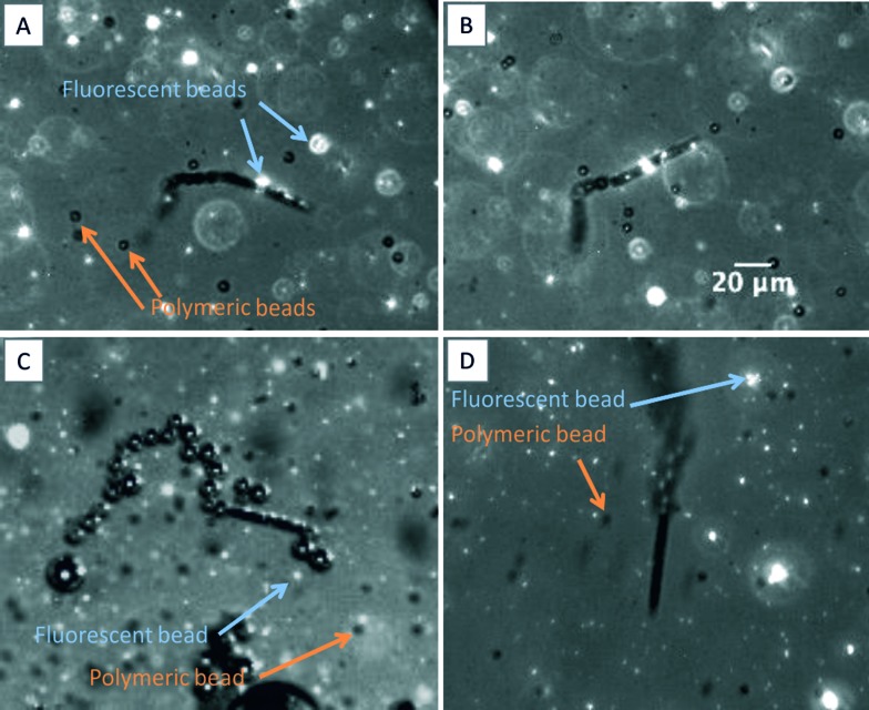
To test the selectivity of our immobilization system, we carried out a similar experiment in which non-biotinylated polymeric beads (Thermo scientific, cat. no. 7505A) were used together with biotin-functionalized fluorescent beads. The micrographs presented in Fig. 2 corroborate the selectivity of our functionalization system (see also video S2 in the ESI†). After moving in a solution containing fluorescent biotinylated beads and non-biotinylated polymeric beads for several minutes, the surface of the micromotors is only covered with those that are biotinylated (Fig. 2A–C). It is possible to observe again that only half of the micromotor surface is coated with the fluorescent beads (Fig. 2A and C). Fig. 2D shows the control experiment in which no functionalization is observed.
Fig. 2. (A–C) Streptavidin functionalized micromotors moving in a solution containing biotinylated (fluorescent) and non-biotinylated (polymeric) beads. The micromotors only carry biotinylated beads on their surface, showing the selectivity of our system. (D) Control experiment in which no fluorescent beads are trapped.
Trapping biofunctionalized micromotors
Finally, the biofunctionalized micromotors were placed in a heart-shaped microfluidic chip, which traps them following the principles previously reported by our group.36
The polydimethylsiloxane (PDMS)-based microfluidic chip was prepared using the Sylgard 184 Silicone Elastomer KIT (Dow Corning, MI, USA). First, the polymer and the cross-linking agent were hand-mixed in a 10 : 1 ratio and degassed in a vacuum chamber for 30 minutes. Then, the PDMS mixture was slowly poured into a petri dish containing the silicon masters previously fabricated and cured at 100 °C for 15–20 minutes. The chips were finally cut, peeled and placed in microscope glass slides to facilitate their handling. Before each experiment, the surfaces of the chips were treated with oxygen plasma to make them hydrophilic (1 minute, 80 W and an O2 flux of 5 sccm).
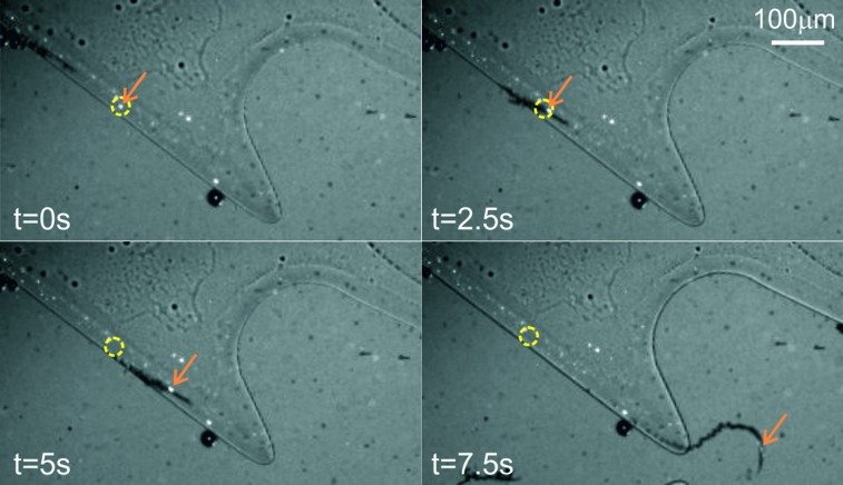
When placed in the chip, the biofunctionalized micromotors exhibited a behaviour similar to their non-functionalized counterpart and were gradually trapped on the heart-shaped chamber over time. Moreover, it was possible to observe how the micromotors transport biotinylated components inside the chamber (Fig. 3, see also video S3 in the ESI†).
Fig. 3. Timelapse of a micromotor entering the trapping area carrying a biotinylated bead. The orange arrow points to a biotinylated bead captured on the surface of a micromotor and the yellow circle serves as a reference to observe the movement of the bead.
Since the functionalized micromotors were trapped in the heart-shaped structure while the beads were immobilized on their surface, it was expected that the concentration of the beads in the trapping chamber increased as the amount of micromotors in the chamber grew overtime. To confirm this, the micromotors, together with 1.8 × 10⁷ fluorescent beads per milliliter, were placed in the main reservoir obtaining a final concentration of 7.5% H2O2 and 0.1% Triton X-100 in PBS, and the increase in the bead-count in the heart-shaped chamber was quantified over a certain period of time. To avoid considering additional mechanisms not related to the functionalization of micromotors, two control experiments were also performed. In the first one, the increase in the number of beads when no micromotors were present in the chamber was quantified to measure the influence of the diffusion of fluorescent beads. The second control experiment consisted of using non-functionalized micromotors to account for the mixing generated thanks to the bubble propulsion mechanism.22 The incorporation of microjets induces the active mixing of the fluid which leads to higher mobility of the solution, leading to a slightly higher accumulation of the beads compared with having no microjets and with only beads in the solution. However, when specifically functionalized microjets capture and transport actively fluorescent beads to the heart-like reservoir, the coupled microjet-bead – and the rest of the suspended beads – gets trapped in a significantly larger amount. The heart-shaped chamber was emptied and rinsed with water at the end of each experiment to avoid cumulative effects of the experiments performed.
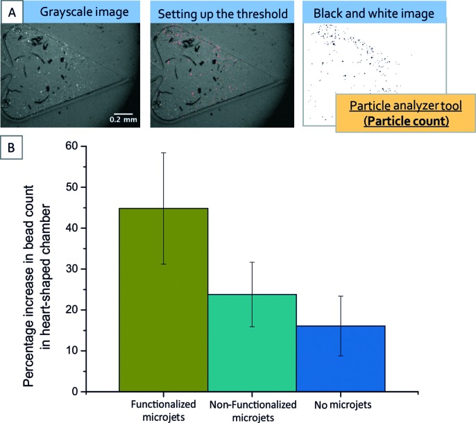
The recorded videos were analysed in order to quantify the amount of beads present in the trapping chamber at an initial time point (t 0) and 75 seconds later (t 1). The particle analyser tool from the software Fiji was used for this quantification as follows: from the recorded movies, images separated by a time period of 75 s were extracted and the appropriate threshold value was set up to convert the grayscale images into black and white images, and remove potential interferences caused by bubbles present in the liquid. Finally, the particle analyser tool was used in order to perform an automatized bead count. The percentage increase was calculated as the ratio of the difference in the final and initial count of beads to the final number of beads. Fig. 4A shows an example of the image analysis process.
Fig. 4. Quantification of the percentage increase in the number of beads in the heart-shaped reservoir. (A) Explains the image process followed using the particle analyser tool from the software Fiji. (B) Results of the quantification for three different cases: no micromotors, non-functionalized micromotors, and functionalized micromotors. The final 41% increase can be attributed to diffusion, mixing and functionalized rockets transporting the cargoes.
Fig. 4B summarizes our quantification process and shows that, with our system, an increase of approximately 41% is observed when micromotors functionalized with streptavidin are used for the trapping experiments as compared to the 25% increase observed with non-functionalized micromotors and the 15% observed with no micromotors.
Conclusions
The trapping of functionalized micromotors represents an alternative system for the concentration of components that can be immobilized on the micromotor surface. Although the concentrating efficiency of other systems might be higher, our platform requires no external mechanism during the process, which might be advantageous to some applications and which might, in the future, facilitate the creation of compact and portable systems.
Footnotes
References
- Gravesen P., Branebjerg J., Jensen O. S. J. Micromech. Microeng. 1993;3:168–182. [Google Scholar]
- Lei K. F. J. Lab. Autom. 2012;17:330–347. doi: 10.1177/2211068212454853. [DOI] [PubMed] [Google Scholar]
- Mark D., Haeberle S., Roth G., von Stetten F., Zengerle R. Chem. Soc. Rev. 2010;39:1153–1182. doi: 10.1039/b820557b. [DOI] [PubMed] [Google Scholar]
- Hua Y. J., Jemere A. B., Dragoljic J., Harrison D. J. Lab Chip. 2013;13:2651–2659. doi: 10.1039/c3lc50401h. [DOI] [PubMed] [Google Scholar]
- Lin C.-C., Hsu J.-L., Lee G.-B. Microfluid. Nanofluid. 2011;10:481–511. [Google Scholar]
- de Jong J., Lammertink R. G. H., Wessling M. Lab Chip. 2006;6:1125–1139. doi: 10.1039/b603275c. [DOI] [PubMed] [Google Scholar]
- Foote R. S., Khandurina J., Jacobson S. C., Ramsey J. M. Anal. Chem. 2005;77:57–63. doi: 10.1021/ac049136w. [DOI] [PubMed] [Google Scholar]
- Solvas X. C. I., Turek V., Prodromakis T., Edel J. B. Lab Chip. 2012;12:4049–4054. doi: 10.1039/c2lc40746a. [DOI] [PubMed] [Google Scholar]
- Ramadan Q., Gijs M. A. M. Analyst. 2011;136:1157–1166. doi: 10.1039/c0an00654h. [DOI] [PubMed] [Google Scholar]
- Chen G. D., Alberts C. J., Rodriguez W., Toner M. Anal. Chem. 2010;82:723–728. doi: 10.1021/ac9024522. [DOI] [PMC free article] [PubMed] [Google Scholar]
- Sundararajan S., Lammert P. E., Zudans A. W., Crespi V. H., Sen A. Nano Lett. 2008;8:1271–1276. doi: 10.1021/nl072275j. [DOI] [PubMed] [Google Scholar]
- Sundararajan S., Sengupta S., Ibele M. E., Sen A. Small. 2010;6:1479–1482. doi: 10.1002/smll.201000227. [DOI] [PubMed] [Google Scholar]
- Zhao G., Wang H., Sanchez S., Schmidt O. G., Pumera M. Chem. Commun. 2013;49:5147–5149. doi: 10.1039/c3cc41962b. [DOI] [PMC free article] [PubMed] [Google Scholar]
- Burdick J., Laocharoensuk R., Wheat P. M., Posner J. D., Wang J. J. Am. Chem. Soc. 2008;130:8164–8165. doi: 10.1021/ja803529u. [DOI] [PubMed] [Google Scholar]
- Wang J. Lab Chip. 2012;12:1944–1950. doi: 10.1039/c2lc00003b. [DOI] [PubMed] [Google Scholar]
- Garcia M., Orozco J., Guix M., Gao W., Sattayasamitsathit S., Escarpa A., Merkoci A., Wang J. Nanoscale. 2013;5:1325–1331. doi: 10.1039/c2nr32400h. [DOI] [PubMed] [Google Scholar]
- Campuzano S., Kagan D., Orozco J., Wang J. Analyst. 2011;136:4621–4630. doi: 10.1039/c1an15599g. [DOI] [PubMed] [Google Scholar]
- Sanchez S., Solovev A. A., Schulze S., Schmidt O. G. Chem. Commun. 2011;47:698–700. doi: 10.1039/c0cc04126b. [DOI] [PubMed] [Google Scholar]
- Solovev A. A., Sanchez S., Pumera M., Mei Y. F., Schmidt O. G. Adv. Funct. Mater. 2010;20:2430–2435. [Google Scholar]
- Pumera M. Chem. Commun. 2011;47:5671–5680. doi: 10.1039/c1cc11060h. [DOI] [PubMed] [Google Scholar]
- Sanchez S., Solovev A. A., Mei Y., Schmidt O. G. J. Am. Chem. Soc. 2010;132:13144–13145. doi: 10.1021/ja104362r. [DOI] [PubMed] [Google Scholar]
- Soler L., Magdanz V., Fomin V. M., Sanchez S., Schmidt O. G. ACS Nano. 2013;7:9611–9620. doi: 10.1021/nn405075d. [DOI] [PMC free article] [PubMed] [Google Scholar]
- Soler L., Sanchez S. Nanoscale. 2014;6(13):7175–7182. doi: 10.1039/c4nr01321b. [DOI] [PMC free article] [PubMed] [Google Scholar]
- Balasubramanian S., Kagan D., Hu C. M. J., Campuzano S., Lobo-Castanon M. J., Lim N., Kang D. Y., Zimmerman M., Zhang L. F., Wang J. Angew. Chem., Int. Ed. 2011;50:4161–4164. doi: 10.1002/anie.201100115. [DOI] [PMC free article] [PubMed] [Google Scholar]
- Kagan D., Campuzano S., Balasubramanian S., Kuralay F., Flechsig G. U., Wang J. Nano Lett. 2011;11:2083–2087. doi: 10.1021/nl2005687. [DOI] [PubMed] [Google Scholar]
- Orozco J., Campuzano S., Kagan D., Zhou M., Gao W., Wang J. Anal. Chem. 2011;83:7962–7969. doi: 10.1021/ac202029k. [DOI] [PubMed] [Google Scholar]
- Campuzano S., Orozco J., Kagan D., Guix M., Gao W., Sattayasamitsathit S., Claussen J. C., Merkoci A., Wang J. Nano Lett. 2012;12:396–401. doi: 10.1021/nl203717q. [DOI] [PMC free article] [PubMed] [Google Scholar]
- Solovev A. A., Smith E. J., Bufon C. C. B., Sanchez S., Schmidt O. G. Angew. Chem., Int. Ed. 2011;50:10875–10878. doi: 10.1002/anie.201102096. [DOI] [PubMed] [Google Scholar]
- Hong Y. Y., Diaz M., Cordova-Figueroa U. M., Sen A. Adv. Funct. Mater. 2010;20:1568–1576. [Google Scholar]
- Sanchez S., Ananth A. N., Fomin V. M., Viehrig M., Schmidt O. G. J. Am. Chem. Soc. 2011;133:14860–14863. doi: 10.1021/ja205012j. [DOI] [PubMed] [Google Scholar]
- Soler L., Martinez-Cisneros C., Swiersy A., Sanchez S., Schmidt O. G. Lab Chip. 2013;13:4299–4303. doi: 10.1039/c3lc50756d. [DOI] [PMC free article] [PubMed] [Google Scholar]
- Garcia-Gradilla V., Orozco J., Sattayasamitsathit S., Soto F., Kuralay F., Pourazary A., Katzenberg A., Gao W., Shen Y. F., Wang J. ACS Nano. 2013;7:9232–9240. doi: 10.1021/nn403851v. [DOI] [PubMed] [Google Scholar]
- Wang W., Castro L. A., Hoyos M., Mallouk T. E. ACS Nano. 2012;6:6122–6132. doi: 10.1021/nn301312z. [DOI] [PubMed] [Google Scholar]
- Zhao G. J., Sanchez S., Schmidt O. G., Pumera M. Chem. Commun. 2012;48:10090–10092. doi: 10.1039/c2cc35671f. [DOI] [PubMed] [Google Scholar]
- Safarik I., Safarikova M. J. Chromatogr. B: Biomed. Sci. Appl. 1999;722:33–53. [PubMed] [Google Scholar]
- Restrepo-Perez L., Soler L., Martinez-Cisneros C. S., Sanchez S., Schmidt O. G. Lab Chip. 2014;14:1515–1518. doi: 10.1039/c3lc51419f. [DOI] [PMC free article] [PubMed] [Google Scholar]
- Wang Z. H., Jin G. J. Immunol. Methods. 2004;285:237–243. doi: 10.1016/j.jim.2003.12.002. [DOI] [PubMed] [Google Scholar]
- Williams R. A., Blanch H. W. Biosens. Bioelectron. 1994;9:159–167. doi: 10.1016/0956-5663(94)80108-8. [DOI] [PubMed] [Google Scholar]
- Frederix F., Bonroy K., Reekmans G., Laureyn W., Campitelli A., Abramov M. A., Dehaen W., Maes G. J. Biochem. Biophys. Methods. 2004;58:67–74. doi: 10.1016/s0165-022x(03)00150-7. [DOI] [PubMed] [Google Scholar]
- Camarero J. A. Biopolymers. 2008;90:450–458. doi: 10.1002/bip.20803. [DOI] [PubMed] [Google Scholar]
- Love J. C., Estroff L. A., Kriebel J. K., Nuzzo R. G., Whitesides G. M. Chem. Rev. 2005;105:1103–1169. doi: 10.1021/cr0300789. [DOI] [PubMed] [Google Scholar]
- Mei Y. F., Huang G. S., Solovev A. A., Urena E. B., Moench I., Ding F., Reindl T., Fu R. K. Y., Chu P. K., Schmidt O. G. Adv. Mater. 2008;20:4085–4090. [Google Scholar]
Associated Data
This section collects any data citations, data availability statements, or supplementary materials included in this article.


