Abstract
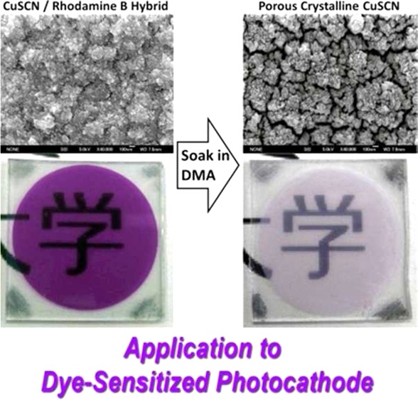
Nanostructured hybrid thin films of CuSCN and rhodamine B (RB) are electrochemically self-assembled (ESA) by cathodic electrolysis in an ethanol/water mixture containing Cu2+, SCN–, and RB. By selecting the solvent, Cu2+/SCN– ratio, and the concentration of RB, we demonstrate several control parameters in the film formation. High loading of RB into the film has been achieved to reach a CuSCN:RB volume ratio of approximately 2:1. The RB solid could almost completely be extracted from the hybrid film by soaking the film in dimethylacetamide (DMA), leading to a large increase of the surface area. The crystallographic orientation of the nanostructure with respect to the substrate can be controlled. Efficient quenching of fluorescence of RB has been observed for the CuSCN/RB hybrid film, implying hole injection from RB excited state to CuSCN. Photoelectrochemical study on the porous crystalline CuSCN obtained after the DMA treatment and sensitized with RB revealed sensitized photocathodic action under visible light illumination, indicating the potential usefulness of the porous CuSCN electrodes for construction of tandem dye-sensitized solar cells.
Introduction
The discovery of electrochemical self-assembly (ESA) of nanostructured hybrid thin films of inorganic semiconductors and organic dyes has opened a new synthetic route for obtaining photoanode material for dye-sensitized solar cells (DSSCs).1−5 This method bypasses the high-temperature sintering that is typically needed for nanoparticulate TiO2 electrodes, which prevents the use of conductive plastic substrates. We have previously demonstrated the use of ESA with the ZnO structures for the construction of photoanodes.4,5 Minor addition of water-soluble dye molecules with substituents for anchoring to ZnO surface brought about a significant impact on the crystal growth for evolution of various nanostructures and alteration of the crystallographic orientation of the film. Importantly, the coprecipitation of dye molecules does not necessarily deteriorate the crystallinity of ZnO. In the case of ZnO/eosin Y (EY) hybrid thin films, vertically aligned interconnected and crystalline nanowires of ZnO are formed.3,5 The space between the ZnO nanowire is filled with aggregates of EY. The solid EY can be completely removed by soaking the hybrid film in a mild alkaline such as dilute KOH aq. (ca. pH 11) without dissolving ZnO. Thus, prepared ZnO thin films, consisting of large single-crystalline grains with internal porous structure, to be called “porous crystal ZnO”, have large surface area for adsorption of photosensitizer dye in a large amount and high crystallinity for efficient transport of electrons; therefore, it can achieve high incident photon to current conversion efficiency (IPCE) of around 90%.3,5
With the DSSC application in mind, it would be highly interesting to find a compatible system for fabricating sensitized photocathodes. Recently, Powar et al. have succeeded in achieving 1.3% conversion efficiency for a DSSC in an inverted structure employing a porous p-NiO electrode sensitized with a specially designed dye to achieve a high rectification with kinetically reversible Co(II/III) ethylene diamine complex electrolyte.6 We have been seeking to perform cathodic electrodeposition of CuSCN, a p-type, wide-bandgap semiconductor, into highly crystallized thin films at low temperature.7−10 CuSCN has been frequently used as a hole conductor in nanostructured solar cells11−16 and also as a sensitized photocathode in combination with hole-injecting dyes.5,10,17,18 Therefore, ESA of CuSCN-based hybrid thin films could serve nicely as a counterpart to the well-established ZnO-based hybrid systems.
Our first attempt for ESA of CuSCN hybrid system was to employ dye molecules having soft Lewis basic −NCS groups.5 On the basis of the hard and soft, acid and base (HSAB) principle, choice of dyes equipped with hard Lewis basic carboxylate is suited for binding to hard Lewis acidic Ti(IV) sites of TiO2 or Zn(II) sites of ZnO. Because Cu(I) of CuSCN is a typical soft Lewis acid, the soft sulfur atom of the −NCS should be a good match. As such, dyes having −NCS groups, the popular N3 dye (Ru(dcbpy)2(NCS)2, dcbpy = 2,2′-bipyridine-4,4′-dicarboxylic acid) and FLTC (fluorescein isothiocyanate) were added to the bath for electrodeposition of CuSCN. As expected, colored CuSCN thin films incorporating N3 and FLTC were obtained, while EY added for comparison did not cause any change for the formation of CuSCN, which is of course normally colorless. The addition of N3 and FLTC also brought about the evolution of characteristic nanostructure of CuSCN, clearly indicating their action as structure directing agents (SDAs). The electrodeposited CuSCN/dye hybrid thin films exhibited dye-sensitized photocathodic properties, evincing the intimate chemistry between CuSCN and dyes having soft basic anchors, which appear to be the key for hole injection from the dye excited state.
Following the success with the above-mentioned strategy, the idea further developed to try substituting Cu(I) of CuSCN with cationic dyes instead of substituting NCS– with dyes having −NCS group. Among commercially readily available dyes, we have employed rhodamine B (RB), which is cationic because of the presence of an ammonium group. This strategy indeed showed positive results as we have seen a clear effect of RB as an SDA for formation of nanostructure and as a cause of changes in crystallographic orientation of CuSCN.8 However, it was not possible to extract the loaded RB molecules by any kind of post treatment to obtain highly porous structure as in the case of the ZnO/EY hybrid system. Because the mechanism of CuSCN electrodeposition was poorly understood at the time of the previous work, the conditions were not properly chosen to achieve hybrid thin films with composition similar to that of ZnO/EY, for which EY could occupy close to half of the volume of the precipitated solid.
In this work, we present a method for ESA of hybrid CuSCN/RB nanoporous films in which the RB SDA may be nearly completely removed. By varying the relative concentration of Cu2+ and SCN–, we can change the crystal orientation of the resulting nanostructure with respect to the substrate. We explore several preliminary dyes and show photoinduced hole transfer to the CuSCN; in addition, we tested the best systems in photoelectrochemical studies to check the dye-sensitized photocathodic properties. At this stage, we still do not have a good combination of dye and electrolyte for CuSCN. However, the recent progress with the photocathodic DSSC presents a new opportunity to improve the efficiency of dye-sensitized cathode systems that can eventually be combined with existing sensitized anodes for realization of a tandem solar cell to achieve high efficiencies in very simple structures.19,20
Experimental Section
Inorganic chemicals such as lithium thiocyanate dihydrate (LiSCN·2H2O, Kishida), copper(II) perchlorate hexahydrate (Cu(ClO4)2·6H2O, Sigma-Aldrich), and lithium perchlorate (LiClO4, Sigma-Aldrich) and organic solvents such as N,N-dimethylacetamide (DMA, Wako) and ethanol (Wako) were of special grade and used as purchased. Rhodamine B (RB, Kanto) was of over 98% purity. Fluorine-doped tin oxide (FTO) coated transparent conductive glass (sheet resistance, 7–8 Ω/sq, 1.1 mm thick soda lime glass, Asahi-DU, Asahi Glass) was used as the substrate to electrodeposit the CuSCN thin films. Milli-Q ultrapure water (>18 MΩ) was used throughout the experiments.
The FTO glass was cut into 25 × 25 mm2, degreased by ultrasonically cleaning in detergent and acetone, and finally rinsed with water. It was mounted into a specially designed electrode holder for a homemade rotating disc electrode (RDE) system.21 The active area of the FTO glass electrode was regulated to a 22 mm diameter circle concentric to the rotating electrode holder by applying a masking tape (Nitto Denko N-300). The use of a RDE system to introduce laminar flow is essential for obtaining CuSCN thin films with perfect homogeneity and with a high reproducibility because the reaction occurs under the mass transport limited regime.7,10 The FTO glass RDE that serves as a working electrode is placed with the active surface down and in the center of the electrochemical cell of a cylindrical shape, equipped with a water-jacket for temperature control (25 °C), together with auxiliary electrodes, a Pt wire counter and a Ag/AgCl reference. A mixture of water and ethanol (1:3 in volume ratio) was used for preparation of the deposition bath. Cu(ClO4)2 and LiSCN were dissolved at 9 and 3 or 3 and 9 mM for Cu2+ rich or SCN– rich bath, respectively, while 0.1 M LiClO4 was also added as the supporting electrolyte. A small amount of RB up to 1.0 mM was added to obtain CuSCN/RB hybrid thin films. A Hokuto-Denko HSV-100 electrochemical system was used for potential control and current monitoring. Cathodic electrolysis at +0.2 V (vs Ag/AgCl) for 5 min and with a rotation speed of 500 rpm resulted in CuSCN thin films which were washed with water, dried under air at room temperature, and subjected to characterization.
UV–vis absorption spectra of the films were measured in transmission on a Hitachi U-4000 or a PerkinElmer Lambda 1050 spectrophotometer. Fluorescence spectra of the film samples were measured on a Photon Technology International QuantaMaster40 equipped with two double-monochromators and a cooled PMT detector. Aside from the CuSCN/RB hybrid thin film, CuSCN hybrid with fluorescein isothiocyanate (FLTC), nile blue (NB), cresyl violet (CV), 3,4,9,10-perylenetetracarboxylic acid diimide (PTCDI), and quinacridone (QD), as well as thin solid films of only these chromophores, were prepared for comparison in the fluorescence study. Those of RB, FLTC, NB, and CV were prepared by hybrid electrodeposition and spin coating their 1 mM solutions in ethanol on a slide glass, while those of PTCDI and QD were prepared by vacuum evaporation either onto an electrodeposited porous CuSCN or on a slide glass. Surface morphology of the films was observed by field emission scanning electron microscopy (FE-SEM, Hitachi S-4800 or JEOL JSM-6700F). Crystallographic characterization of the film was conducted by measuring X-ray diffraction (XRD) patterns on a Rigaku RINT Ultima III instrument.
The amount of RB loaded into the film was determined by dissolving a known area of the film into a known volume of ammonia solution and measuring its absorption spectrum. The amount of electrodeposited CuSCN was determined by measuring the amount of Cu2+ in the ammonia solution dissolving the film according to the classical colorimetric analysis method,22 employing sodium N,N-diethyldithiocarbamate trihydrate (DDTC, Wako) to chelate copper ion for extraction with ethyl acetate which exhibits a strong absorption at 436 nm (ε = 1.3 × 10⁴ M–1 cm–1). Comparison with the amount of consumed charge yields Faradaic efficiency for the electrodeposition of CuSCN. A part of the loaded RB molecules could also be extracted by soaking the film in DMA. From comparison of the absorption spectra before and after the DMA treatment, the fraction of the extractable RB could be determined. The extraction of RB also results in increased porosity of the film. Several thin-film samples after the DMA treatment were scratched off the substrate. The surface area of powder samples prepared in this manner was determined by Brunauer–Emmet–Teller (BET) analysis of the Kr gas sorption measurement conducted on a Micromeritics Tristar II 3020 system.
Photoelectrochemical measurements on CuSCN thin film electrodes have been performed in a three-electrode setup with a Pt wire counter and a saturated calomel reference electrode (SCE). Porous CuSCN thin films were sensitized by soaking them in a 1.0 mM RB aqueous solution for 1 h. A 0.1 M aqueous solution of methylviologen dichloride (MV2+, Sigma-Aldrich) was used as the electrolyte. The electrode was illuminated from its front side with a visible light generated by a 500 W Xe lamp (Ushio) filtered by UV (<420 nm) and IR (>800 nm) cutoff filters (intensity, 100 mW cm–2).
Results and Discussion
Direct crystallization of β-CuSCN occurs as a consequence of cathodic reduction of Cu2+ in the presence of SCN– both from aqueous and ethanolic solutions.10 Rhodamine B is commercially provided as chloride and is well-soluble both to water and ethanol. However, RB could not be dissolved above ca. 30 μM when 0.1 M LiClO4 was added to water as a supporting electrolyte because of the salting-out effect, making it difficult to achieve a high loading of RB to CuSCN. On the other hand, ethanol dissolved RB too well to hinder its loading to CuSCN. Therefore, a mixture of water and ethanol (25:75 volume ratio) was chosen as the solvent that provided good solubility of all chemicals and achieved an efficient loading of RB molecules during electrochemical growth of CuSCN.
Our previous studies on electrodeposition of CuSCN employing a rotating disk electrode revealed that the growth of CuSCN is typically limited by transport of complexes of Cu2+ and SCN– that form in solution, achieving practically 100% Faradaic efficiency for the formation of CuSCN.7 In aqueous solutions, only a 1-to-1 complex is formed,7 while a neutral 1-to-2 complex is also formed and participates in the electrochemical reaction in ethanolic solutions containing excess of SCN–.10 Thus, the overall reaction is expressed by eq 1 for the aqueous solution and both eqs 1 and 2 operate in the ethanolic solution.
| 1 |
| 2 |
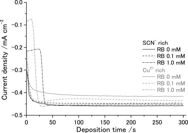
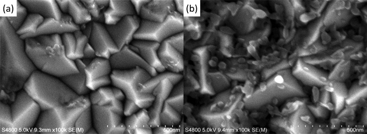
The chronoamperograms measured during the electrodeposition can be seen in Figure 1. Following the initial rise of the current, diffusion-limited steady-state current is reached both for the Cu2+ rich and SCN– rich solutions. However, a slightly higher current is seen for the SCN– rich solution. This should reflect the formation of a bis-coordinated Cu(II) thiocyanato complex which has a diffusion coefficient that is somewhat higher than that of the monocoordinated complex in ethanol as revealed in our electrochemical analysis.10 The addition of RB to the bath causes a slight decrease of the steady-state current in the SCN– rich bath, whereas a slight increase of the current was observed in the Cu2+ rich bath, which could be caused by the chemical interaction of the complexes with RB molecules. Even though the addition of RB caused a slight decrease of Faradaic efficiency for the precipitation of CuSCN (vide infra), the film thickness increased linearly with the consumed charge (see Figure 1S of Supporting Information). As the current is almost constant, the film thickness can simply be controlled by the time of the electrolysis. However, it should be mentioned that the high addition of RB at 1.0 mM brings about a characteristic change in the initial profile of the current. In such baths, the current stays small in the beginning of the electrolysis then abruptly increases to achieve the steady-state current. The surface of the FTO glass substrates was observed by SEM before and after the jump of the current (Figure 2). There is apparently no change before the jump as the bare surface of the FTO layer is seen. After the jump, tiny CuSCN particles are deposited, especially at the bottom of the valleys and along the ridges of the pyramidal FTO grains. Although the reason for the incubation time is unclear, it is probable that RB molecules are adsorbed on the FTO surface, hindering the nucleation of CuSCN.
Figure 1.
Chronoamperograms measured during electrodeposition of CuSCN and CuSCN/RB hybrid thin films onto an FTO coated glass RDE (ω = 500 rpm) at +0.2 V (vs Ag/AgCl) in ethanol/water (75/25, v/v) mixed solutions containing Cu(ClO4)2 and LiSCN in Cu2+ rich (9 and 3 mM, respectively) and SCN– rich (3 and 9 mM, respectively) compositions; 0.1 M LiClO4 as a supporting electrolyte; and 0, 0.1, or 1.0 mM RB.
Figure 2.
SEM pictures of the surface of the FTO glass substrates after electrolysis for 20 s (a) and 30 s (b) in an ethanol/water (75/25, v/v) mixed solution containing 3 mM Cu(ClO4)2, 9 mM LiSCN, 0.1 M LiClO4, and 1.0 mM RB.
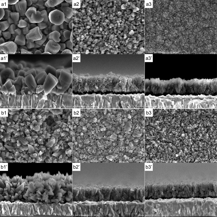
CuSCN/RB hybrid thin films were electrodeposited for 5 min both from SCN– rich and Cu2+ rich baths while changing the concentration of RB. The morphology of the pure CuSCN film looks totally different for those deposited from SCN– rich and Cu2+ rich baths (panels a1 and b1 of Figure 3, respectively). The former consists of large rounded hexagonal columnar particles, whereas the latter shows assemblies of spiky particles. Rhombohedral β-CuSCN has an elongated hexagonal unit cell with lattice constants of a = b = 3.857 Å and c = 16.449 Å.23 As discussed below, the XRD patterns of the films indicate that films of a1 and b1 are oriented for the c-axis perpendicular with the substrate. The hexagonal faces of the deposits in a1 should thus correspond to the (003) planes of CuSCN, while those faces creating the spikes should probably be of the (101) planes. Such differences can be caused by the change of the stability of the crystal faces by the change of the chemical composition of the bath influencing the dissolution and recrystallization of CuSCN during the electrodeposition (eq 3).
| 3 |
When RB is added to the bath, purple-colored CuSCN/RB hybrid thin films were obtained. As the concentration of RB increased, the color of the film got deeper, indicating the increased loading of RB into the film. At the same time, the morphology of the film drastically changed (panels a2, a3, b2, and b3 of Figure 3). Characteristic nanostructures are created as the particle size becomes small. As discussed later, the loaded RB molecules can almost completely be extracted by dipping the film shown in a3 in dimethylacetamine (DMA), making it highly porous. The shape of the particles differs from sample to sample, especially as recognized from the cross sections, indicating anisotropic crystal growth promoted by RB addition.
Figure 3.
SEM photographs of CuSCN and CuSCN/RB hybrid thin films electrodeposited from SCN– rich (a) and Cu2+ rich (b) baths containing 0 (a1 and b1), 0.3 (a2 and b2) and 1.0 mM (a3 and b3) RB. a1′–a3′ and b1′–b3′ correspond to the cross section of a1–a3 and b1– b3, respectively. The films were observed after soaking them in DMA for removal of RB.
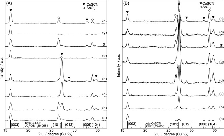
Changes of XRD patterns on RB addition are shown in Figure 4 for SCN– rich and Cu2+ rich baths. All these patterns indicate diffraction peaks assigned to β-CuSCN aside from those originating from SnO2 of the FTO substrate. The relative intensity of the diffraction peaks of the film samples, however, are different from those of the powder diffraction standard. It is also changes for different RB concentrations and for SCN– rich (A) and Cu2+ rich (B) baths, indicating changes of their crystallographic orientation. Two representative diffraction peaks arising from the (003) and the (101) planes are taken to evaluate the orientation change. While the (003) planes are perpendicular to the c-axis, the (101) planes are nearly parallel to the c-axis, crossing with the (003) planes at 78.5° angle because of the elongated unit cell structure. Therefore, the relative change of the (003) and (101) peak intensities is a good measure for examining how the c-axis of CuSCN is oriented with respect to the substrate plane. According to the method described in the literature,24 the orientation indices (OI) are calculated as follows. The intensity factor (IF) of the standard powder sample is calculated for the respective crystal planes as
| 4 |
| 5 |
taking the intensities indicated in ref (23). The IF of the film samples are calculated from the (003) and (101) peak counts of each measured XRD pattern.
| 6 |
| 7 |
The ratio of the IF of the film with respect to that of the powder standard is defined as the OI.
| 8 |
| 9 |
When OI(hkl) is larger than 1, the film has a tendency to orient (hkl) planes in parallel with the substrate; when smaller than 1, just the opposite. The calculated OIs are plotted in Figure 5. Pure CuSCN thin films electrodeposited without RB show high OI(003), indicating their preferential orientation of the c-axis perpendicular with the substrate, irrespective of the SCN– rich and Cu2+ rich bath compositions. Such preferential orientation nicely matches with the arguments for their morphological features described above, namely, the hexagonal facet of the columnar grain in Figure 3a1 and the bevels of the spiky grains in Figure 3b1 corresponding to the (003) and (101) planes, respectively. Minor addition of RB to the bath then drastically increases the OI(101) upon decrease of OI(003), indicating the change of the crystallographic orientation to lay down the c-axis in parallel with the substrate. Such preference is most prominent when [RB] = 0.3 mM, for both the SCN– rich and Cu2+ rich baths. However, the higher addition of RB abruptly changes the orientation back to the one in which the c-axis is perpendicular with the substrate in the case of the SCN– rich bath, whereas the OI(101) value only moderately decreases for the Cu2+ rich bath. Consequently, highly porous CuSCN thin films with totally different crystallographic orientations, namely, the c-axis perpendicular and parallel with the substrate are obtained for the highest end of the RB addition to the SCN– rich and Cu2+ rich baths, respectively. The reason for the complex change of the crystallographic orientation is unclear. However, it is obvious that such changes are caused by the difference of the chemical stability of the facets of CuSCN crystals in different environments, not only by the SCN–/Cu2+ balance but also by the added RB molecules.
Figure 4.
XRD patterns of CuSCN and CuSCN/RB hybrid thin films electrodeposited from SCN– rich (A) and Cu2+ rich (B) baths containing 0 (a), 0.1 (b), 0.2 (c), 0.3 (d), 0.4 (e), 0.5 (f), 0.7 (g), and 1.0 mM (h) RB.
Figure 5.
Change of crystallographic orientation of CuSCN and CuSCN/RB hybrid thin films by changing concentration of RB added to the SCN– rich and Cu2+ rich baths.
The amount of RB loaded into CuSCN during electrodeposition for 300 s from the SCN– rich and Cu2+ rich baths is plotted as a function of RB concentration (Figure 6). The amount of RB precipitated together with CuSCN increases as its concentration in the bath increases, although not proportionally but showing a leveling off trend. The loading efficiency in the SCN– rich bath is clearly higher than that in the Cu2+ rich, especially for the low RB concentration range. Some properties of the CuSCN/RB hybrid thin films electrodeposited from the SCN– rich bath are summarized in Table 1.
Figure 6.
Change of the amount of RB loaded into CuSCN as a function of RB concentration added to the SCN– rich and Cu2+ rich baths.
Table 1. Properties of CuSCN/RB Hybrid Thin Films Electrodeposited from 3 mM Cu(ClO4)2 + 9 mM LiSCN + x mM RB Bath for 300 s.
| RB conc (mM) | passed charge (mC cm–2) | electrodeposited CuSCN (×10–6 mol cm–2) | faradic efficiency (%) | film thickness (μm) | precipitated RB (×10–8 mol cm–2) | RB fluxa (×10–9 mol cm–2 s–1) | fraction of RB precipitatedb (%) | volume ratioc (CuSCN:RB) | volume ratiod (CuSCN:RB:void) |
|---|---|---|---|---|---|---|---|---|---|
| 0 | 133 | 1.46 | 104 | 1.45 | – | – | – | 100:0 | 43:0:57 |
| 0.1 | 134 | 1.38 | 98 | 1.45 | 1.07 | 0.203 | 17.5 | 91:9 | 41:5:54 |
| 0.5 | 131 | 1.31 | 95 | 0.82 | 2.23 | 1.02 | 7.3 | 81:19 | 68:16:16 |
| 1.0 | 125 | 1.09 | 83 | 0.80 | 3.03 | 2.03 | 5.0 | 72:28 | 58:23:19 |
Calculated for ω = 500 rpm from Levich equation by employing the bulk concentration of RB and its diffusion coefficient in water at 25 °C (3.2 × 10⁻⁶ cm2 s–1).
Calculated by dividing the amount of RB loaded into the film by the amount of RB transported to the electrode surface in 300 s.
Calculated by using the formulas weight of CuSCN (121.6 g mol–1), the density of CuSCN (2.84 g cm–3), the molar weight of RB (479.02 g mol–1) and the density of RB solid (0.79 g cm–3 at 20 °C).
The volume of the void was calculated by subtracting the volumes of CuSCN and RB from the total volume of the film determined from the film thickness.
Increase of the concentration of RB in the bath led to a slight decrease of the consumed charge because of the decrease of the steady-state current and the presence of the incubation time for [RB] = 1.0 mM. At the same time, Faradaic efficiency for the precipitation of CuSCN gradually decreased. The film thickness significantly decreased, as seen in the crosssectional SEM pictures in Figure 3. While the amount of electrodeposited CuSCN decreased, the amount of precipitated RB increased. The change of the film thickness, however, is mostly caused by the change of the porosity as seen in the volume ratio for CuSCN, RB, and void for the hybrid film. As the diffusion coefficient of the RB molecule could be found only as measured in water solution, we took this value to calculate the flux of RB for its given concentration under the rotating condition employed in this study. The sticking efficiency of RB was then estimated by calculating the fraction of RB loaded into the film as compared to its maximum amount transported toward the electrode surface during the electrolysis. The highest efficiency of 17.5% was achieved for [RB] = 0.1 mM, and that value decreased as the bulk concentration got higher. It is obvious that the precipitation of RB is not under the control of its transport but rather its stability or rate of attaching to CuSCN. When the molar amounts of precipitated CuSCN and RB are determined, the fraction of the volume occupied by these components in the hybrid film can be calculated by taking their molar weight and density, either taking into account or not taking into account the total volume of the film. The CuSCN:RB ratio gives a rough idea up to how much volume of the precipitated solid can be occupied by RB. An approximately 2:1 ratio seems to be reachable for this system, which is equivalent to that for the ZnO/eosin Y hybrid system reported elsewhere.25 The CuSCN:RB:void ratio correlates to the porosity of the film. As shown in the following section, the loaded RB molecules can be removed from the hybrid films with high RB loading, leaving some empty space within the CuSCN grains. The voids in the as-deposited films occur from spaces between the CuSCN/RB hybrid grains, while that occupied by RB is converted to the tiny pores formed inside CuSCN grains after extraction of RB. A total of 40–60% porosity should then be achieved for these films.
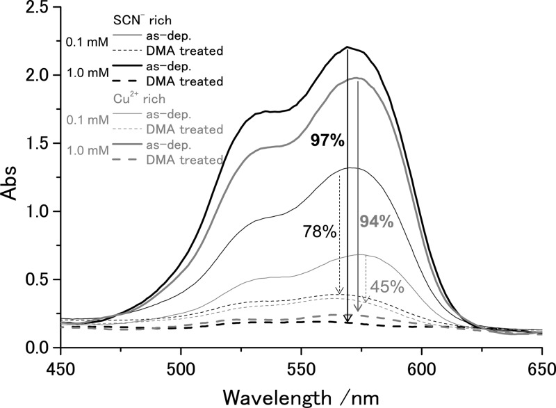
When the hybrid films are soaked in dimethylacetamide (DMA), the films were bleached as the RB molecules were extracted, as seen from the change of the absorption spectra before and after the treatment (Figure 7). For the films with small RB loading, RB molecules could be only partly removed, whereas those with high RB loading allowed almost complete desorption of RB. The film with the highest RB loading, namely, that deposited from the SCN– rich bath containing 1.0 mM RB, became nearly colorless because 97% of the loaded dye was removed as estimated from the absorbance change at the maximum of RB absorption. As discussed above, the extraction of RB should result in tiny nanopores enlarging the surface area of the CuSCN films. This was confirmed by Brunauer–Emmet–Teller analysis of Kr sorption measurements (Figure 8). The surface area of about 6 m2 g–1 is already reached for the film deposited from the Cu2+ rich bath without RB. It only moderately increases by hybridization with RB and its extraction for the Cu2+ rich baths. On the other hand, that of the film deposited from the SCN– rich bath results in only about 4 m2 g–1 without RB, and it greatly increases up to 12.6 m2 g–1 when [RB] = 1.0 mM. The roughness factor (RF), defined as the ratio of the actual surface area per projected film area, of about 17 is reached as calculated from the amount of electrodeposited CuSCN shown in Table 1. Considering the small film thickness of 0.8 μm, this roughness factor is reasonably high because RF of several hundred can be reached when the thickness is increased to a few tens of micrometers. These thicknesses and RF values are comparable to those of materials typically used for dye-sensitized solar cells. Using the reported growth conditions, we were able to extend the growth time and film thickness by roughly a factor of 5 before inducing any cracking in the film. Growing thicker films would require further optimization of the growth parameters.
Figure 7.
Transmission absorption spectra of as-electrodeposited CuSCN/RB hybrid thin films (solid lines) and those after soaking the films for 1 h in dimethylacetamide (DMA) (dashed lines). The percentage of RB extracted by DMA treatment is also indicated. The CuSCN/RB thin films were electrodeposited from SCN– rich (black lines) and Cu2+ rich (gray lines) baths containing 0.1 (thin lines) or 1.0 mM (thick lines) of RB.
Figure 8.
Change of specific surface area of CuSCN/RB hybrid thin films after extraction of RB by DMA treatment as determined by Kr sorption measurements.
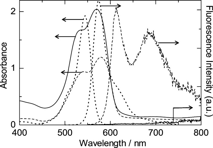
As we have succeeded in obtaining highly porous crystalline CuSCN thin films, it is of significant interest to check its usefulness as a dye-sensitized photocathode. However, no stably adsorbed sensitizer dye for efficient hole injection to CuSCN has been previously discovered. We first checked fluorescence quenching for several fluorescent dye molecules attached to CuSCN, such as fluorescein isothiocyanate (FLTC), cresyl violet (CV), nile blue (NB), 3,4,9,10-perylene tetracarboxylic acid diimine (PTCDI), quinacridone (QC), and RB. FLTC can be coelectrodeposited with CuSCN because of the presence of a soft basic thiocyanate moiety that is expected to act as an anchor to the soft acidic Cu(I) sites of CuSCN.5 The electrodeposited CuSCN/FLTC hybrid thin film in fact exhibited dye-sensitized photocathodic behavior upon visible light illumination.5 Addition of NB and CV to the deposition bath for CuSCN also resulted in formation of hybrid thin films because of their cationic character by the presence of ammonium group, the same as that of RB. PTCDI and QC lack such chemical affinity to CuSCN, so they were simply vacuum evaporated on top of the porous CuSCN. All of these molecules exhibit fluorescence in solution, but NB and CV actually did not show measurable fluorescence in solid state. Whereas no quenching was observed for PTCDI and QC, fluorescence of FLTC and RB was strongly quenched for their electrodeposited hybrid thin films. In particular, that of RB was almost totally quenched as shown in Figure 9, while imperfect quenching was observed in the case of the CuSCN/FLTC hybrid (see Figure 2S of Supporting Information for the spectra). Because the valence band edge of CuSCN is expected to lie around −5.3 eV (vs VAC), the highest occupied molecular orbital level of all these dye molecules is deep enough to transfer holes to CuSCN from a thermodynamic point of view. It is supposed that the strong chemical affinity of FLTC and RB to CuSCN is crucial for hole injection to take place actually, unlike PTCDI and QC which are only in physical contact with the surface of CuSCN.
Figure 9.
Absorption and fluorescence spectra of electrodeposited CuSCN/RB hybrid thin film (solid lines), solid RB thin film prepared by spin coating (dashed lines), and 20 μM RB solution in ethanol (dotted lines). The excitation wavelength for the film samples and the solution were 535 and 530 nm, respectively. The fluorescence spectrum of the RB solution is attenuated for better comparison with other spectra because it is far stronger than the other samples.
One could learn more from the spectra in Figure 9. Monomeric RB molecules in solution exhibit a sharp absorption peak at 545 nm and a weak shoulder around 505 nm. A strong and sharp fluorescence spectrum occurs like a mirror image of the absorption spectrum, exhibiting a peak at 574 nm and a weak shoulder around 620 nm. The solid thin film of RB aggregate shows a characteristic change of the absorption spectrum with a maximum at 579 nm and another distinctive peak at 541 nm. It has been shown that dimerization of RB molecules in solution leads to an increase of the abosorbance of the short side shoulder because of enhanced intermolecular interaction in parallel arrangement of the chromophore, namely, in H-aggregate form.26,27 The great enhancement of the blue-side shoulder band to become a clearly distinguished satellite peak for the solid RB film is obviously caused by the strong electronic interaction in the molecular solid in H-aggregate form. This solid RB film exhibits a characteristic fluorescence. The sharp peak at 613 nm should reflect a monomolecularly confined fluorescence band, which is also red-shifted compared to that of the RB monomer solution. On the other hand, the broad character centered at 687 nm should be related to the transition involving the intermolecular band, which exists only in the aggregates. The absorption spectrum of the electrodeposited CuSCN/RB hybrid thin film closely resembles that of the solid RB thin film, exhibiting a character for the H-aggregate. However, both peaks are blue-shifted to 536 and 570 nm for aggregate and monomer bands, respectively, indicating different environments of the RB molecules which are subjected to chemical interaction with CuSCN. Then, the fluorescence of RB in the hybrid film is totally quenched. Because characteristic fluorescence was clearly monitored for RB in the solid state, the total quenching of the fluorescence in the hybrid film should be caused by hole transfer from the exited state of RB to the valence band of CuSCN.
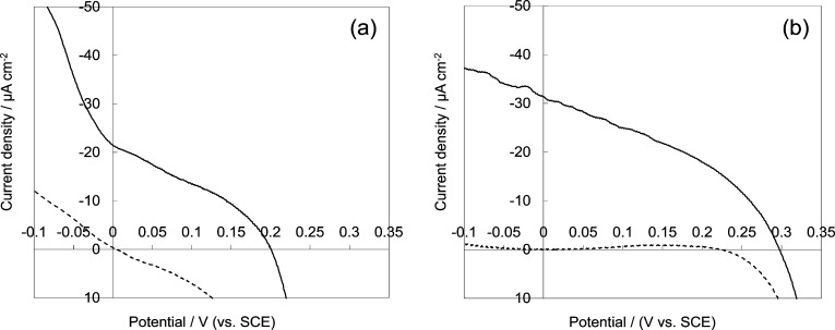
We carried out photoelectrochemical measurements on RB-sensitized porous CuSCN electrodes. The electrodes were the pure CuSCN with a relatively high surface area, that electrodeposited from Cu2+ rich bath without RB, and a highly porous CuSCN made by electrodeposition from a SCN– rich bath containing 1.0 mM RB which then was removed by the DMA treatment. These electrodes were soaked in an aqueous solution of RB for sensitization. Thus, we prepared a dye-sensitized photocathode with the RB dye shown to undergo photoinduced hole transfer. However, the lack of a suitable redox electrolyte is a significant problem for studying photocathodic sensitization of CuSCN.5,17 Iodide/triiodide redox electrolyte typically used in DSSCs reacts with CuSCN to convert it to CuI that dissolves rather well in many polar organic solvents. Adsorption of RB molecules to CuSCN was unfortunately not so stable, as recognized by the fact that the electrolyte solution was clearly colored by desorbed RB both for organic and aqueous solutions. For this reason, it was not useful to use Co complex redox systems, which are kinetically highly reversible, because fast recombination from the uncovered surface of CuSCN or exposed FTO actually killed the voltage under illumination. Stably adsorbed highly rectifying dyes are needed for effective use of Co redox,6 which are missing at this stage. Thus, we have employed an aqueous solution of methylviologen chloride as the electron acceptor. The electrode was reasonably stable in this electrolyte and exhibited a clear photocathodic action under visible light illumination as shown in Figure 10. Pure CuSCN film sensitized with RB exhibits about 0.2 V photocurrent onset voltage and 22 μA cm–2 photocathodic current; these values increased to ca. 0.3 V and 32 μA cm–2 for the porous CuSCN electrode prepared by hybrid electrodeposition with RB, extraction of RB, and readsorption of RB. Clearly, enlarged surface area made the color of the film more intense than that of the pure CuSCN, obviously contributing to the increased current. Poorly rectified dark current for pure CuSCN (Figure 10a) can be associated with the the bare FTO surface being in contact with the electrolyte, allowing direct charge transfer to methylviologen. Because the porous crystalline CuSCN (Figure 10b) covers the FTO better than pure CuSCN, the dark current is well-rectified and higher voltage is achieved. Despite efforts to find a stable dye–electrolyte solution combination, the RB dye still desorbs from the surface during measurement, likely contributing to the unusually low photocurrent.
Figure 10.
I–V curves measured at bulk CuSCN (a) electrodeposited without RB and porous crystalline CuSCN (b) electrodeposited with 1.0 mM RB and RB subsequently removed by DMA treatment, measured in the dark (hashed lines) and under illumination (solid lines) with visible light (100 mW cm–2) generated by a 500 W Xe lamp equipped with UV and IR cutoff filters. The CuSCN films were sensitized by readsorbing RB by soaking in a 0.5 mM RB aqueous solution for 1 h. The electrolyte was a deaerated aqueous solution of 0.1 M methylviologen chloride.
We have developed a method for obtaining a highly porous and nicely crystallized p-CuSCN thin film by electrodeposition. By selection of the bath composition, it has become possible to load RB molecules in an amount to occupy as much as 30% of the total volume of precipitated solid, from which the loaded RB could be removed by soaking the film in DMA. Such a process can now be regarded as a counterpart of the entire technology developed for ZnO/eosin Y hybrid electrodeposition for processinghigh-performance porous crystalline ZnO-based dye-sensitized photoanodes.5 Porous structures are created by the RB molecules within highly crystallized CuSCN. Not only the porous nanostructure but also the crystallographic orientation of CuSCN could be controlled by the choice of the bath composition. The resulting porous crystalline CuSCN thin film has been utilized as dye-sensitized photocathode to prove its usefulness as a counterpart of dye-sensitized ZnO photoanodes. However, limited surface area as well as the lack of good hole-injecting dye stable on the CuSCN surface and suitable redox electrolyte remain as challenges for efficiency improvement of the photocathode. Because recent studies have discovered a good sensitizer for p-NiO in combination with Co complex redox systems,6 there is a good hope of finding one for p-CuSCN. The successfully constructed efficient dye-sensitized CuSCN photocathode can be combined with existing dye-sensitized photoanodes to achieve high-efficiency tandem DSSCs in a very simple structure sandwiching a common redox electrolyte solution by two photoelectrodes.
Acknowledgments
The present study has received financial support from Grant-in-Aid for Scientific Research (B) on “One-Pot Synthesis of Inorganic/Organic Hybrid Solar Cells” (24350103) from the Ministry of Education, Culture and Sports (MEXT) of Japan and Japan Regional Innovation Strategy Program by the Excellence on “Establishment of International Center for Advanced Organic Electronics Research” from Japan Science and Technology Agency (JST), National Nature Science Foundation of China (51102011), the Austrian FWF Wittgenstein Award, and the J-RISE (JST) Yamagata University–Johannes Kepler University collaboration.
Supporting Information Available
Film thickness versus consumed charge for CuSCN/RB hybrid thin films electrodeposited from an ethanol/water (75/25, v/v) mixed solution containing 3 mM Cu(ClO4)2, 9 mM LiSCN, 0.1 M LiClO4, and 1.0 mM RB (Figure 1S); absorption and fluorescence spectra of electrodeposited CuSCN/FITC (fluorescein isothiocyanate) hybrid thin film and solid FITC thin film prepared by spin coating (Figure 2S). This material is available free of charge via the Internet at http://pubs.acs.org.
The authors declare no competing financial interest.
Supplementary Material
References
- Yoshida T.; Miyamoto K.; Hibi N.; Sugiura T.; Minoura H.; Schlettwein D.; Oekermann T.; Schneider G.; Wöhrle D. Self Assembled Growth of Nano Particulate Porous ZnO Thin Film Modified by 2,9,16,23-Tetrasulfophthalocyanatozinc(II) by One-Step Electrodeposition. Chem. Lett. 1998, 7, 599–600. [Google Scholar]
- Yoshida T.; Terada K.; Schlettwein D.; Oekermann T.; Sugiura T.; Minoura H. Electrochemical Self-Assembly of Nanoporous ZnO/Eosin Y Thin Films and Their Sensitized Photoelectrochemical Performance. Adv. Mater. 2000, 12, 1214–1217. [Google Scholar]
- Yoshida T.; Pauporté T.; Lincot D.; Oekermann T.; Minoura H. Cathodic Electrodeposition of ZnO/Eosin Y Hybrid Thin Films from Oxygen-Saturated Aqueous Solution of ZnCl2 and Eosin Y. J. Electrochem. Soc. 2003, 150, C608–C615. [Google Scholar]
- Yoshida T.; Iwaya M.; Ando H.; Oekermann T.; Nonomura K.; Schlettwein D.; Wöhrle D.; Minoura H. Improved Photoelectrochemical Performance of Electrodeposited ZnO/EosinY Hybrid Thin Films by Dye Re-adsorption. Chem. Commun. (Cambridge, U.K.) 2004, 400–401. [DOI] [PubMed] [Google Scholar]
- Yoshida T.; Zhang J.; Komatsu D.; Sawatani S.; Minoura H.; Pauporté T.; Lincot D.; Oekermann T.; Schlettwain D.; Tada H.; et al. Electrodeposition of Inorganic/Organic Hybrid Thin Films. Adv. Funct. Mater. 2009, 19, 17–43. [Google Scholar]
- Pawar S.; Daeneke T.; Ma M. T.; Fu D.; Duffy N. W.; Götz G.; Weidelener M.; Mishra A.; Bäuerle P.; Spiccia L.; et al. Highly Efficient p-Type Dye-Sensitized Solar Cells Based on Tris(1,2-diaminoethane)Cobalt(II)/(III) Electrolytes. Angew. Chem., Int. Ed. 2013, 52, 602–605. [DOI] [PubMed] [Google Scholar]
- Okabe K.; Selk Y.; Oekermann T.; Yoshida T. Cathodic Electrodeposition of CuSCN Thin Films. Trans. Mater. Res. Soc. Jpn. 2008, 33, 1325–1328. [Google Scholar]
- Selk Y.; Yoshida T.; Oekermann T. Variation of the Morphology of Electrodeposited Copper Thiocyanate Films. Thin Solid Films 2008, 516, 7120–7124. [Google Scholar]
- Sun L.; Yoshida T. Cathodic Electrodeposition of ZnO and CuSCN Thin Films in the Presence of Glutathione. Trans. Mater. Res. Soc. Jpn. 2009, 34, 283–286. [Google Scholar]
- Sun L.; Ichinose K.; Sekiya T.; Sugiura T.; Yoshida T. Cathodic Electrodeposition of p-CuSCN Nanorod and Its Dye-Sensitized Photocathodic Property. Phys. Procedia 2011, 14, 12–24. [Google Scholar]
- O’Regan B.; Schwartz D. T. Large Enhancement in Photocurrent Efficiency Caused by UV Illumination of the Dye-Sensitized Heterojunction TiO2/RuLL′NCS/CuSCN: Initiation and Potential Mechanisms. Chem. Mater. 1998, 10, 1501–1509. [Google Scholar]
- Kumara G. R. R. A.; Konno A.; Senadeera G. K. R.; Jayaweera P. V. V.; De Silva D. B. R. A.; Tennakone K. Dye-Sensitized Solar Cell with the Hole Collector p-CuSCN Deposited from a Solution in n-Propyl Sulphide. Sol. Energy Mater. Sol. Cells 2001, 69, 195–199. [Google Scholar]
- O’Regan B.; Lenzmann F.; Muis R.; Wienke J. A Solid-State Dye-Sensitized Solar Cell Fabricated with Pressure-Treated P25–TiO2 and CuSCN: Analysis of Pore Filling and IV Characteristics. Chem. Mater. 2002, 14, 5023–5029. [Google Scholar]
- Tsujimoto K.; Nguyen D.-C.; Ito S.; Nishino H.; Matsuyoshi H.; Konno A.; Kumara R. G. A.; Tennakone K. TiO2 Surface Treatment Effects by Mg2+, Ba2+, and Al3+ on Sb2S3 Extremely Thin Absorber Solar Cells. J. Phys. Chem. C 2012, 116, 13465–13471. [Google Scholar]
- Levy-Clement C.; Tena-Zaera R.; Ryan M. A.; Katty A.; Hodes G. CdSe-Sensitized p-CuSCN/Nanowire n-ZnO Heterojunctions. Adv. Mater. 2005, 17, 1512–1515. [Google Scholar]
- Tena-Zaera R.; Katty A.; Bastide S.; Levy-Clement C.; O’Regan B.; Muñoz-Sanjose V. ZnO/CdTe/CuSCN, a Promising Heterostructure to Act as Inorganic Eta-Solar Cell. Thin Solid Films 2005, 483, 372–377. [Google Scholar]
- O’Regan B.; Schwartz D. T. Efficient Photo-Hole Injection from Adsorbed Cyanine Dyes into Electrodeposited Copper (I) Thiocyanate Thin Films. Chem. Mater. 1995, 7, 1349–1354. [Google Scholar]
- Fernando C. A. N.; Kumarawadu I.; Takahashi K.; Kitagawa A.; Suzuki M. Crystal Violet Dye-Sensitized Photocurrent by Participation of Surface States on p-CuSCN Photocathode. Sol. Energy Mater. Sol. Cells 1999, 58, 337–347. [Google Scholar]
- He J.; Lindström H.; Hagfeldt H.; Lindquist S.-E. Dye-Sensitized Nanostructured Tandem Cell-First Demonstrated Cell with a Dye-Sensitized Photocathode. Sol. Energy Mater. Sol. Cells 2000, 62, 265–273. [Google Scholar]
- Gibson E. A.; Smeigh A. L.; Le Pleux L.; Fortage J.; Boschloo G.; Blart E.; Pellegrin Y.; Odobel F.; Hagfeldt A.; Hammarström L. A p-Type NiO-Based Dye-Sensitized Solar Cell with an Open-Circuit Voltage of 0.35 V. Angew. Chem., Int. Ed. 2009, 48, 4402–4405. [DOI] [PubMed] [Google Scholar]
- Yane T.; Koyama A.; Hiramatsu K.; Isogai Y.; Ichinose K.; Yoshida T. Development of Electrodeposition System Employing 8 Rotating Disc Electrodes for Highly Reproducible Synthesis of Zinc Oxide Thin Films. Electrochemistry 2012, 80, 891–897. [Google Scholar]
- Sandell E. B.Colorimetric Determination of Traces of Metals, 3rded.; Interscience Publishers: New York, 1959. [Google Scholar]
- Joint Committee on Powder Diffraction Standard, JCPDS No. 29-0581.
- Yoshida T.; Tochimoto M.; Schlettwein D.; Wöhrle D.; Sugiura T.; Minoura H. Self-Assembly of Zinc Oxide Thin Films Modified with Tetrasulfonated Metallophthalocyanines by One-Step Electrodeposition. Chem. Mater. 1999, 11, 2657–2667. [Google Scholar]
- Zhang J.; Sun L.; Ichinose K.; Funabiki K.; Yoshida T. Effect of Anchoring Groups on Electrochemical Self-Assembly of ZnO/Xanthene Dye Hybrid Thin Films. Phys. Chem. Chem. Phys. 2010, 12, 10494–10502. [DOI] [PubMed] [Google Scholar]
- Selwyn J. E.; Steinfeld J. I. Aggregation Equilibria of Xanthene Dyes. J. Phys. Chem. 1972, 76, 762–774. [Google Scholar]
- Mchedlov-Petrosyan N. O.; Kholin Y. V. Aggregation of Rhodamine B in Water. Russ. J. Appl. Chem. 2004, 77, 414–422. [Google Scholar]
Associated Data
This section collects any data citations, data availability statements, or supplementary materials included in this article.


