Abstract
In this work, we design and study a highly sensitive beam steering device that integrates a spiral plasmonic antenna with a subwavelength metallic waveguide. The short effective wavelength of the surface plasmon polaritons (SPPs) mode supported by the metallic waveguide is exploited to dramatically miniaturize the device and improve the sensitivity of the beam steering. Through introducing a tiny displacement of feed point with respect to the geometrical center of the spiral plasmonic antenna, the direction of the radiation can be steered at considerably high angles. Simulation results show that steering angles of 8°, 17° and 34° are obtainable for a displacement of 50 nm, 100 nm and 200 nm, respectively. Benefiting from the reduced device size and the shorter SPP wavelength, the beam steering sensitivity of the beam steering is improved by 10-fold compared with the case reported previously. This miniature plasmonic beam steering device may find many potential applications in quantum optical information processing and integrated photonic circuits.
Plasmonic antennas can efficiently convert light from free space into sub-wavelength volumes and vice versa, facilitating the manipulation of light at nanoscale1. Unlike dielectric optics that is bound by the diffraction limit, plasmonic antennas have the ability to pack energy into a joint resonance of the photon and the free electrons in the metal. Consequently, plasmonic antennas are considered as the ideal structures to interface single emitters and single photons2,3,4, with the ability of interrogating a single molecule with a single quantum of light, or collecting a photon emitted by a single emitter.
Recent advances in plasmonic antennas offer tremendous opportunities to control the emission characteristics from nanoscale quantum emitters. Plasmonic antennas with this sort of functionality is also referred to as optical transmitting antennas that efficiently convert the localized feeding energy to free space propagating optical radiation5. By coupling nanoscale emitters to plasmonic antennas, the properties of the SPPs resonance in the vicinity of the emitters are imprinted to and carried by the emitted photons from the emitters. Taking advantages of the classical antenna theory that was proven still useful at optical frequency6, a variety of antenna configurations are designed to realize certain desired far-field radiation characteristics. For examples, Yagi-Uda antenna6,7, bull's eye antenna8, and cross antenna9 have been demonstrated to control the characteristics of photons emission from quantum emitters in terms of intensity, directivity and polarization.
Besides these far field radiation characteristics, the capability of steering the photon emission direction is highly desirable with many potential applications. Several methods have been reported to control the emission direction via changing the groove-to-center distance of the plasmonic antenna10 or the dipole-to-surface distance11. However, the practicality of these methods is limited by the fixed steering angle or low directivity. Recently, a technique using spiral plasmonic antenna has been demonstrated with the ability of tailoring the properties of emitted photons holistically in terms of not only intensity, directivity and polarization but also orbital angular momentum as well as emission direction5,12,13,14. Dynamical beam steering is realized by introducing a displacement between the feed point (i.e. excitation location of nano emitters) and the geometrical center of the spiral antenna. For a displacement of 500 nm, steering angle of 7° has been experimentally demonstrated12. Although the steering angle increases with the displacement, the emission pattern eventually deteriorate for large displacement due to the finite antenna aperture size. Therefore, this method has limitations for applications that require a wider range of the steerable emission direction. In this paper, we present a novel approach to realize a miniature wide-angle beam steering device through integrating a spiral plasmonic antenna with a metallic waveguide. A theoretical model and three-dimensional (3D) finite element method (FEM) models are developed to analyze the functionalities of the device and yield an in-depth understanding of the beam steering mechanism. The results show that the sensitivity of the beam steering can be significantly improved, leading to a larger steering angle with a smaller amount of required displacement to the feed point. Besides, compared with the previous design12, the dimension of the novel beam steering device can be reduced by more than the half.
Results
Physical mechanism
The beam steering mechanism can be explained by the interference of the transmitted waves from the optical antenna12. Considering an electric dipole placed over an antenna, the field emitted from the dipole excites SPPs on the antenna surface, serving as the feed to the antenna. Depending on whether the dipole is placed in free space or in confined geometries, the SPP excitation may be primarily attributed to the propagating or the evanescent fields emitted from the dipole, respectively. The optical path difference (OPD) Δl from the diametrically opposing sides of the antenna is calculated to be Δl = 2Δr × λ0/λspp, where Δr is the displacement of the dipole from the geometrical center of the antenna, λspp and λ0 are the wavelengths of the SPPs on the antenna surface and optical emission in the free space, respectively. When the dipole is displaced from the center, an overall wavefront tilt is developed due to the non-zero OPD, leading to a shift of the far-field radiation peak from the normal direction with a steering angle θ12:
 |
where D is the aperture size of the antenna. This simple analytical model provides important insight into the beam steering characteristics of the spiral antenna. Given the monochromatic optical wavelength and displacement, it can be seen from equation (1) that the sensitivity of the steering angle (Δθ/Δr) can be enhanced by either decreasing the aperture size D or increasing kspp. However, the beam steering effect is referred to the far field of the radiation from the dipole coupled antenna, thus the aperture size need to be large enough with respect to the wavelength of the SPPs, otherwise the beaming effect quickly deteriorates once the excitation moves away from the center. Thus, the minimal aperture size is proportional to the SPPs wavelength. This points out a potential way to enhance the steering sensitivity by decreasing the wavelength of SPPs on the antenna surface, which gives rise to an increasing numerator and decreasing denominator of equation (1) simultaneously.
Demonstration of the feasibility to increase beam steering sensitivity by decreasing SPPs wavelength
The dispersion relation of the SPPs propagating at the dielectric/metal interface can be expressed as15:
 |
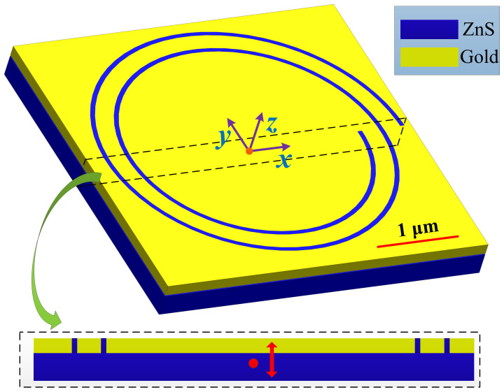
where εm and εd are the relative permittivity of the metal and dielectric, respectively. A simple way to decrease the SPPs wavelength is to use dielectric material with higher index of refraction. To prove the relationship between the SPP wavelength and the steering angle, a three-dimensional geometry has been modeled using commercial FEM software (COMSOL). As shown in Fig. 1, a 2-turn right-hand Archimedes' spiral slot with slot width of 40 nm is etched through a 150 nm gold film on a ZnS substrate (n = 2.26). The slot is filled with the same dielectric. The thickness of the spiral antenna is kept unchanged throughout this work. In the cylindrical coordinates, a right-handed-spiral (RHS) can be expressed as r = r0-Λφ/(2π), where Λ equals the SPP wavelength on the planar Au/ZnS interface and r0 denotes the distance from the geometrical center to the innermost slot. An electric dipole is imbedded in the substrate with 10 nm below the Au/ZnS interface. The emission wavelength of the dipole is assumed to be 633 nm. The index of refraction of gold at this wavelength is 0.197 + 3.0908i16. It has been demonstrated experimentally that a spiral antenna with r0 equals to 5λspp provides sufficient beaming effect12.
Figure 1. Diagram of a beam steering device consists of spiral plasmonic antenna and ZnS substrate.
The inset shows the cross section indicated by the dashed box. An electric dipole is imbedded in the substrate and located 10 nm below the Au/ZnS interface. The red arrow indicates the oscillation direction of the dipole.
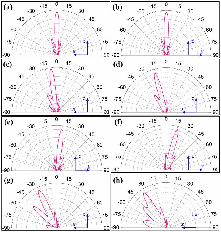
Compared with the case of placing dipole on an Au/Air interface12, r0 can be reduced from 3 μm to 1 μm in this case as the SPPs wavelength at the Au/ZnS interface (190 nm) is much smaller than that at the Au/Air interface (598 nm), leading to a smaller beaming device. The transverse dimension of the device is less than 4 μm, which is 58% smaller than the previous design12. The Fig. 2(a) and 2(b) show the angular radiations in x-z and y-z planes when the dipole is placed at the geometrical center of the spiral antenna. The radiation peaks at 0°, normal to the antenna surface. The emission pattern is highly directional, with full-width-half-maximal (FWHM) of 11.4° and 11.8° in x-z and y-z planes, respectively. By adding more turns of the spiral, the angular width of the radiation emission can be further reduced5. Figure 2(c) shows the angular radiations in x-z plane when the dipole is displaced along x axis from the center by 50 nm. As expected, the emission peak shifts from the normal direction by 8°. The steering angle further increases to 16° when the displacement is 100 nm (shown in Fig. 2(d)). These results agree very well with the theoretical predictions using equation (1), which are calculated to be 7.4° and 15.0° for displacements of 50 nm and 100 nm, respectively (D is nearly 2.6 μm). Compared with the case reported previously12, the beam steering sensitivity is increased by 10 folds, benefiting from both a shorter SPP wavelength and a reduced antenna size. In addition, the emission pattern is well maintained and the angular width of the radiation basically remains constant. Similar phenomena are observed for electric dipole with y-directional displacement. In this case, the steering angles are 7° and 16° when the dipole is moved along y axis for 50 nm and 100 nm, respectively (shown in Fig. 2(e) and 2(f)). In summary, these numerical simulations confirm that the steering angle strongly depends on the wavelength of SPPs and the sensitivity of the beaming direction can be improved by decreasing the wavelength of SPPs. In addition, the validity of the theoretical model is proved and it provides a rough but quick estimation of the steering angle of the far-field emission.
Figure 2. Angular radiation patterns for beam steering device consists of spiral plasmonic antenna and ZnS substrate with different displacements.
For zero displacement: (a, b) line-scans in the x-z and y-z planes. For x-directional displacements of 50 nm, 100 nm, 150 nm and 200 nm: (c, d, g, h) line-scans in the x-z plane. For y-directional displacements of 50 nm and 100 nm: (e, f) line-scans in the y-z plane.
Composite beam steering device design
In recent years, SPPs based photonic devices such as waveguide17, reflector18 and beam splitters19 have gained increasing research interest. Among SPPs waveguides, metal-insulator-metal (MIM) configuration is very promising for compact photonic integration20,21, plasmonic splitter22, etc. As the insulator layer of MIM waveguide is too thin to support photonic modes, the excited dipole decay radiatively only by direct near-field coupling to plasmonic transverse magnetic modes. More importantly, extremely small SPP wavelength can be achieved even for excitation well below SPPs frequency, provided that the dielectric core is sufficiently thin23. Therefore, a carefully designed metallic waveguide substituting the role of ZnS substrate described above can provide even higher steering sensitivity and further reduce the device size.
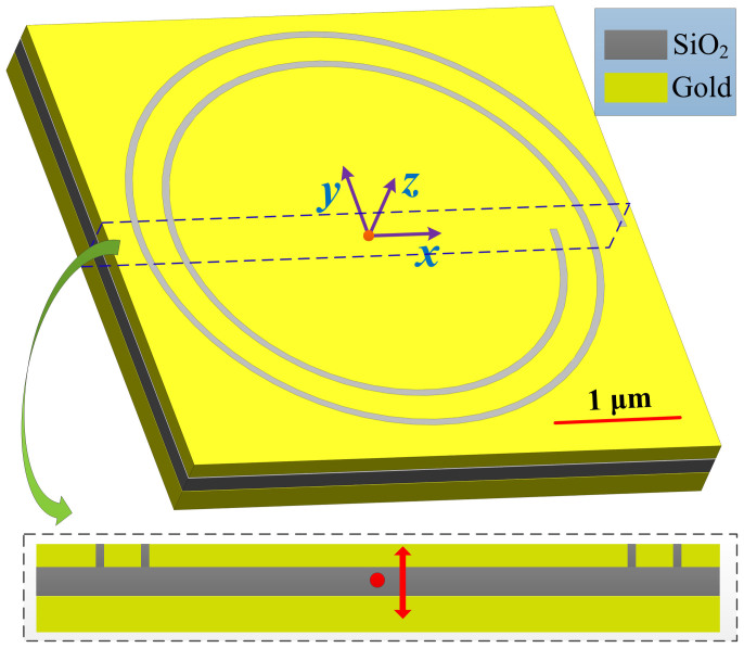
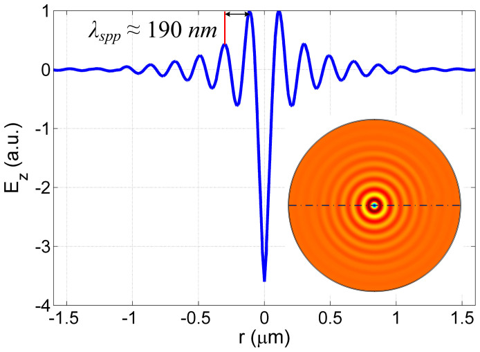
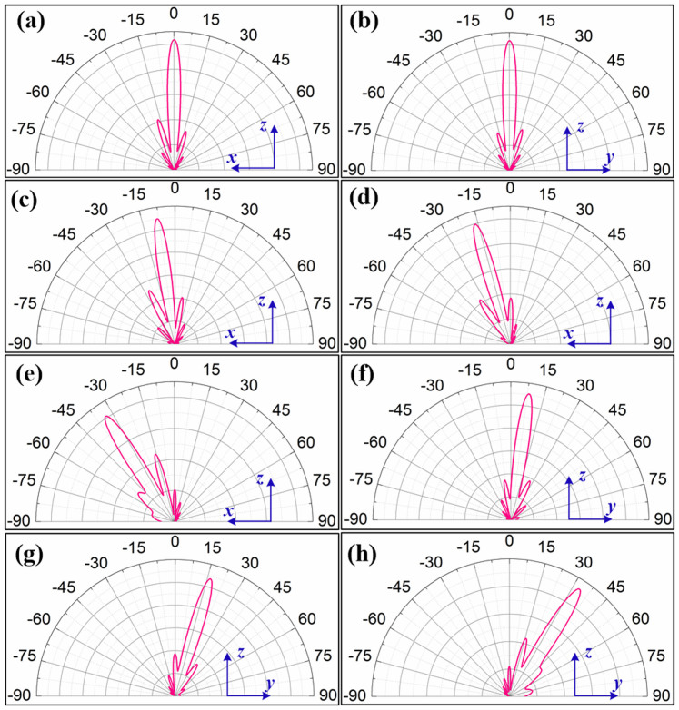
The proposed composite structure is illustrated in Fig. 3. A gold nanodisk with the thickness of 200 nm is placed 20 nm below the spiral surface. The gap in between the spiral and the nanodisk is filled with silicon dioxide (n = 1.5). The central portion of the structure forms an Au-SiO2-Au waveguide. To excite the waveguide, an electric dipole is placed in the middle of the insulating layer with oscillation direction along z axis. As the thickness of the insulating layer is far below the diffraction limit, conventional guided modes cannot exist and the radiation field from the dipole will be transformed into a symmetric SPPs mode that is highly confined within the dielectric core. Inset of Fig. 4 shows the Ez distribution in the middle transverse plane of the insulating layer for dipole emission wavelength of 633 nm. The excitation of a guided mode with 190 nm wavelength can be clearly seen. The SPPs are guided through the slot opening to other side of the spiral antenna and then re-radiate into the free space. The wavelength of SPPs in the metallic waveguide decreases with decreasing thickness of the insulating layer. The effective wavelength of the SPP guided mode is designed to be about 190 nm, equivalent to the case of using ZnS substrate for fair comparison. Therefore, the parameters of the spiral antenna are kept unchanged. For phase matching between the insulating layer of the waveguide and the spiral slot, the filling material in the slot is replaced with SiO2. When the dipole is placed at the geometrical center of the spiral antenna, the emission peak is still normal to the spiral surface with high directivity (Fig. 5(a) and 5(b)). The FWHM of the radiation pattern along x and y axes are 11.4° and 11.7°, respectively. Although the dipole location (distance from Au/SiO2 interface) is an important factor to influence the profile properties of the symmetric SPPs mode in terms of amplitude and wavelength24, a tiny shift of the dipole position in the transverse plane has negligible effect on SPPs wavelength, which is vital for obtaining a far-field radiation pattern with solid spot at the center14. Figure 5(c) and 5(d) show the line-scans along x axis for x-directional displacement of 50 nm and 100 nm, respectively. The radiation field maintains almost the same profile and angular width while steering away from the normal direction for 8° and 17°, respectively. These steering angles are the same with the results shown in Fig. 2(c) and 2(d) because the wavelength of the SPPs collected by the spiral antenna are designed to be the same. It should be noted that the effective wavelength of the guided mode can be further reduced with different design parameters, leading to further enhanced steering sensitivity and smaller device aperture size.
Figure 3. Diagram of the beam steering device consists of spiral plasmonic antenna and subwavelength metallic waveguide.
The inset shows the cross section indicated by the dashed box. An electric dipole is imbedded in the middle of the insulating layer of the waveguide. The red arrow indicates the oscillation direction of the dipole.
Figure 4. Line-scan of the Ez distribution along the dashed line indicated in the inset.
The inset shows the Ez distribution in the middle transverse plane of the insulating layer.
Figure 5. Angular radiation patterns for beam steering device consists of spiral plasmonic antenna and metallic waveguide with different displacements.
For zero displacement: (a, b) line-scans in the x-z and y-z planes. For x-directional displacements of 50 nm, 100 nm and 200 nm: (c, d, e) line-scans in the x-z plane. For y-directional displacements of 50 nm, 100 nm and 200 nm: (f, g, h) line-scans in the y-z plane.
Besides the miniature size and high beam steering sensitivity, this composite beam steering device has an additional advantage of being more robust to the displacement of the feed point. For the design using ZnS, the peak intensity of the first side lobe rises to above 75% with respect to the main lobe at a displacement of more than 150 nm, leading to a distorted emission pattern (shown in Figure 2(g) and 2(h)). Contrarily, the first side lobe peak intensity remains below 50% of the main lobe peak intensity even the displacement increases up to 200 nm. This is because the phase distribution is better maintained in the waveguide even for the large displacement of the dipole, which is crucial to obtain a radiation pattern with good directivity. Figure 5(e) shows the angular radiation pattern in x-z plane when the dipole is displaced 200 nm away from the center along x axis. Despite the increase of one side lobe, the far-field radiation field is still dominated by the peak centered at −34°, corresponding to a steering angle of 34° that agrees with the theoretical prediction (31.2°). Figure 5 (f)–5(h) show the line-scans of the emission patterns along y axis for y-directional displacements of 50 nm, 100 nm and 200 nm, respectively. In this case, the emission is steered along y direction at 8°, 17° and 33°, respectively.
Discussion
In conclusion, we designed and numerically studied a high sensitive beam steering device that combines a spiral plasmonic antenna with a subwavelength metallic waveguide. The guided mode in the metallic waveguide excited by an electric dipole imbedded in the insulating layer is coupled through the spiral plasmonic antenna and radiates into highly directional radiation in the far field. Due to the characteristics of the guided mode in the waveguide, SPPs with shorter effective wavelength can be excited propagating on the antenna surface, an effect that not only improves the sensitivity of the beam steering performance but also reduce the necessary aperture size of the spiral antenna. By introducing a small amount of the displacement of the dipole to the geometrical center of the spiral antenna, both theoretical calculation and numerical simulations demonstrate that wide angle beam steering can be realized. For a device consisted of a 2-turn spiral antenna and an Au-SiO2-Au waveguide with 25 nm SiO2 thickness, steering ranges of +/−8°, +/−17° and +/−34° are obtainable when the dipole is dynamically displaced from the center by +/−50 nm, +/−100 nm and +/−200 nm, respectively, showing a steering sensitivity 10 times higher than the case reported previously due to both reduced device size and shorter SPP wavelength. Besides, the dimension of the device is reduced to only 42% of the previous design with only the spiral antenna. To achieve the real-time dynamic beam steering with the proposed device, the nanoscale emitters can be uniformly spin coated or dip coated inside the waveguide and selectively excited, which are still within the capabilities of modern nanotechnology. One possible way is to selectively excite the emitters inside the waveguide electronically by moving a conductive cantilever to inject electrons locally. Alternatively, a transparent conduction film (TCF) can be adopted to sandwich the emitters between a spiral antenna and a TCF. Due to the intriguing properties of TCF such as electrically conductive and optically transparent, the emitters embedded in the waveguide can be excited by laser beam from the side of the TCF. As a consequence, emitters in different areas can be excited by scanning the excitation locations, leading to a dynamically controlled emission direction. Such a miniature beam steering device may find applications in quantum optical information processing and integrated photonic circuits.
Methods
Simulation method
The full-wave simulations of the characteristics of the devices shown in Fig. 1 and 3 were performed using the radio frequency module of the commercial software COMSOL. The electric dipole is modelled by setting an electric point dipole with electric current dipole moment along the direction normal to the antenna surface (Pz equals to 1 m A). The electric field distributions in the far field are calculated by the postprocessing available in COMSOL.
Author Contributions
G.R. was responsible for the COMSOL simulations. Q.Z. was responsible for the original research concept, and physical interpretation. G.R. wrote the paper with the help of Q.Z.
Acknowledgments
The authors acknowledge the financial support from the Fraunhofer Society through the University of Dayton - Fraunhofer Research Center.
References
- Bharadwaj P., Deutsch B. & Novotny L. Optical antennas. Adv. Opt. Photon. 1, 438–483 (2009). [Google Scholar]
- Curto A. G., Volpe G., Taminiau T. H., Kreuzer M. P., Quidant R. & van Hulst N. F. Unidirectional emission of a quantum dot coupled to a nanoantenna. Science 329, 930–933 (2010). [DOI] [PubMed] [Google Scholar]
- Taminiau T. H., Stefani F. D., Segerink F. B. & Van Hulst N. F. Optical antennas direct single-molecule emission. Nat. Photon. 2, 234–237 (2008). [Google Scholar]
- Chen X., Sandoghdar V. & Agio M. Highly efficient interfacing of guided plasmons and photons in nanowires. Nano Lett. 9, 3756–3761 (2009). [DOI] [PubMed] [Google Scholar]
- Rui G., Nelson R. L. & Zhan Q. Circularly polarized unidirectional emission via a coupled plasmonic spiral antenna. Opt Lett. 36, 4533–4535 (2011). [DOI] [PubMed] [Google Scholar]
- Kosako T., Kadoya Y. & Hofmann H. F. Directional control of light by a nano-optical Yagi-Uda antenna. Nat. Photon. 4, 312–315 (2010). [Google Scholar]
- Dorfmüller J. et al. Near-field dynamics of optical Yagi-Uda nanoantennas. Nano Lett. 11, 2819–2824 (2011). [DOI] [PubMed] [Google Scholar]
- Aouani H. et al. Bright unidirectional fluorescence emission of molecules in a nanoaperture with plasmonic corrugations. Nano Lett. 11, 637–644 (2011). [DOI] [PubMed] [Google Scholar]
- Biagioni P. et al. Cross resonant optical antenna. Phy. Rev. Lett. 102, 256801 (2009). [DOI] [PubMed] [Google Scholar]
- Aouani H. et al. Plasmonic antennas for directional sorting of fluorescence emission. Nano Lett. 11, 2400–2406 (2011). [DOI] [PubMed] [Google Scholar]
- Xi Z. et al. Controllable directive radiation of a circularly polarized dipole above planar metal surface. Opt. Express 21, 30327–30335 (2013). [DOI] [PubMed] [Google Scholar]
- Rui G., Abeysinghe D. C., Nelson R. L. & Zhan Q. Demonstration of beam steering via dipole-coupled plasmonic spiral antenna. Sci. Rep. 3, 7 (2013). [DOI] [PMC free article] [PubMed] [Google Scholar]
- Rui G., Chen W., Abeysinghe D. C., Nelson R. L. & Zhan Q. Beaming circularly polarized photons from quantum dots coupled with plasmonic spiral antenna. Opt. Express 20, 19297–19304 (2012). [DOI] [PubMed] [Google Scholar]
- Rui G., Nelson R. L. & Zhan Q. Beaming photons with spin and orbital angular momentum via a dipole-coupled plasmonic spiral antenna. Opt. Express 20, 18819–18826 (2012). [DOI] [PubMed] [Google Scholar]
- Barnes W. L., Dereux A. & Ebbesen T. W. Surface plasmon subwavelength optics. Nature 424, 824–830 (2003). [DOI] [PubMed] [Google Scholar]
- Palik E. D. Handbook of optical constants. Handbook of optical constants of solids (Academic Press, 1998). [Google Scholar]
- Tanaka K. & Tanaka M. Simulations of nanometric optical circuits based on surface plasmon polariton gap waveguide. Appl. Phy. Lett. 82, 1158–1160 (2003). [DOI] [PubMed] [Google Scholar]
- Wang B. & Wang B. Plasmon Bragg reflectors and nanocavities on flat metallic surfaces. Appl. Phy. Lett. 87, 013107 (2005). [Google Scholar]
- Hu F., Yi H. & Zhou Z. Band-pass plasmonic slot filter with band selection and spectrally splitting capabilities. Opt. Express 19, 4848–4855 (2011). [DOI] [PubMed] [Google Scholar]
- Verhagen E., Dionne J. A., Kuipers L., Atwater H. A. & Polman A. Near-field visualization of strongly confined surface plasmon polaritons in metal−insulator−metal waveguides. Nano Lett. 8, 2925–2929 (2008). [DOI] [PubMed] [Google Scholar]
- Dionne J. A., Lezec H. J. & Atwater H. A. Highly Confined photon transport in subwavelength metallic slot waveguides. Nano Lett. 6, 1928–1932 (2006). [DOI] [PubMed] [Google Scholar]
- Guo Y. et al. A plasmonic splitter based on slot cavity. Opt Express 19, 13831–13838 (2011). [DOI] [PubMed] [Google Scholar]
- Maier S. A. Plasmonics: fundamentals and applications (Springer, 2010). [Google Scholar]
- Xiao G., Ji X., Gao L., Wang X. & Zhou Z. Effect of dipole location on profile properties of symmetric surface plasmon polariton mode in Au/Al2O3/Au waveguide. Front. Optoelectron 5, 63–67 (2012). [Google Scholar]


