

Abstract
Insufficient bone anchoring is a major limitation of artificial substitutes for connective osteoarticular tissues. The use of coatings containing osseoconductive ceramic particles is one of the actively explored strategies to improve osseointegration and strengthen the bone-implant interface for general tissue engineering. Our hypothesis is that hydroxyapatite (HA) particles can be coated robustly on specific assemblies of PVA hydrogel fibers for the potential anchoring of ligament replacements. A simple dip-coating method is described to produce composite coatings made of microscopic hydroxyapatite (HA) particles dispersed in a poly(vinyl alcohol) (PVA) matrix. The materials are compatible with the requirements for implant Good Manufacturing Practices. They are applied to coat bundles of PVA hydrogel fibers used for the development of ligament implants. By means of optical and electronic microscopy, we show that the coating thickness and surface state can be adjusted by varying the composition of the dipping solution. Quantitative analysis based on backscattered electron microscopy show that the exposure of HA at the coating surface can be tuned from 0 to over 55% by decreasing the weight ratio of PVA over HA from 0.4 to 0.1. Abrasion experiments simulating bone-implant contact illustrate how the coating cohesion and wear resistance increase by increasing the content of PVA relative to HA. Using pullout experiments, we find that these coatings adhere well to the fiber bundles and detach by propagation of a crack inside the coating. These results provide a guide to select coated implants for anchoring artificial ligaments.
Keywords: hydroxyapatite, poly(vinyl alcohol), hydrogel, dip-coating, scanning electron microscopy
Introduction
Injuries of soft connective tissues such as ligaments, tendons, or cartilage do not heal well and often require a reconstruction using natural grafts, durable synthetic implants or degradable tissue-engineered scaffolds.1-3 To restore proper physiological function, it is crucial that these reconstructed tissues be well anchored to the bone tissues of the treated joint. In particular, for synthetic implants, failures at the bone-implant interface remain a major limitation.3-5 For bone prosthetics, coating by osseoconductive ceramics has been shown to significantly improve the strength of the anchorage to bone.6-12 How this approach can be applied to soft tissue substitutes currently motivates strong research efforts.6-8,13-16 In particular, methods for coatings that contain bioceramics to enhance osseointegration while still adhering properly to the soft implant remains a challenge. Numerous systems have been developed that are composed of osseoconductive or inductive ceramic particles embedded in a biocompatible polymer matrix.6-8,11,17-19 The exact requirements for the design of such coatings are still not well defined and depend on the implantation site. In particular, it is most likely that a sufficient surface exposure of ceramic particles should be provided to stimulate the activity of neighboring cells and promote growth of bone tissue. The control of this accessibility to bioceramics is central for the osseointegration of permanent coatings but might also play a role for biodegradable coatings at the early stage after implantation. In this article, we investigate a direct approach to make composite hydrogel-hydroxyapatite coatings with a tunable surface exposure of hydroxyapatite created by varying the composition of the coating solution.
The studied coatings are composed of microscopic hydroxyapatite particles embedded in a hydrogel matrix obtained from physically cross-linked poly(vinyl alcohol) (PVA). Such PVA hydrogels form a non-degradable material with excellent biocompatibility.20-22 PVA hydrogels have already shown promising performances for several soft-tissue replacement applications including cartilage15,16,22 and vein valve repair.23 Besides them being biocompatible, PVA hydrogels do not show strong promotion for secured attachment and proliferation of cells.6,7 Several studies have shown that PVA hydrogels can be functionalized by the addition of hydroxyapatite (HA) particles, improving cell adhesion, cell proliferation and osteocalcine levels.12,24-26 Whether these PVA/HA systems can be used as soft tissue implant coatings has been little explored hitherto.
Here, coatings of PVA/HA composite were applied to assemblies of PVA hydrogel fibers, which have recently been shown to reproduce closely the tensile response of native ligaments.27 By promoting osseointegration, these coatings may enhance the anchoring of these ligament substitutes in bone tunnels. The surface exposure rate of hydroxyapatite was quantified using low vacuum electron microscopy, which allows observations in the hydrated state. Implant-coating adhesion and resistance to wear are also key-issues to ensure that the coating will withstand surgery and physiological loads. Both properties were assessed using pull-out experiments and friction-against-bone experiments, respectively. All these results will serve as design considerations to select an appropriate coating composition and process for in vivo studies. In particular, the selected coatings should offer both a large surface exposure of HA particles to ensure accessibility to cells and a cohesion that prevents coating rip-off during and after implantation.
Results
The studied coatings were obtained from a medical grade HA powder produced by blending powders with different particle size distributions. Figure 1A shows the overall particle diameter distribution of the HA powder as measured by dry dispersion. This distribution is broad and ranges from about 1µm to 70 µm. The number average particle diameter is 27 µm and the diameter ranges between 5 µm and 60 µm for 90% of the population. The morphology and shape of the particles were investigated by SEM as shown in Figure 1B. Most particles have a spherical shape and observations of particles sprayed over 1 cm2 show no significant segregation between small and large particles.
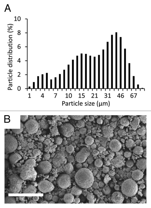
Figure 1. Characterization of HA powder used for coating fabrication: (A) distribution in particle diameter; (B) SEM observation of HA powder in secondary electron mode. Scale bar is 100µm.
The studied coating process is based on a dip-coating approach and is composed of several steps as illustrated in Figure 2: (1) a bundle of PVA fibers forming the implant was soaked in a PVA aqueous solution; (2) after 1 h, it was taken out of the solution and let drip for 1 min to remove any excess of PVA aqueous solution; (3) the PVA solution coating the fibers was physically cross-linked by a succession of freezing and thawing cycles, as described by Hassan and Peppas28; (4) PVA/HA coating was obtained by soaking these precoated PVA bundles in a PVA/HA aqueous solution; (5) after 1 h, samples were let drip for 1 min to remove any excess in PVA/HA solution and (6) were finally cross-linked by repeated freezing-thawing cycles.

Figure 2. Schematic representation of the coating process.
Several coating compositions were produced by varying the weight ratio of PVA over HA, referred to as R in the following. For that, three different aqueous solutions of PVA and HA were prepared as summarized in Table 1. The corresponding R values are 0.4, 0.2, and 0.1. For each solution, water content was adjusted to produce a uniform coating during step 4. In particular, the obtained viscosity allowed a homogeneous dispersion of HA particles with our stirring apparatus and a slow sedimentation kinetic during the whole dip-coating step (1 h). More details on the compositions and processing steps are given the Materials and Methods section. In the following, the PVA/HA coated samples are compared with PVA coated samples obtained right after step 3.
Table 1. Compositions of PVA/HA coating solutions. R gives the weight ratio of PVA over HA.
| H2O (wt%) | PVA (wt%) | HA (wt%) | R (g/g) |
|---|---|---|---|
| 72 | 8 | 20 | 0.4 |
| 52 | 8 | 40 | 0.2 |
| 45 | 5 | 50 | 0.1 |
Both PVA and PVA/HA coated samples were characterized by optical microscopy in dark field reflection mode. In order to remain close to in vivo conditions, all observations were made in a hydrated state by fully immersing the samples in water. Figure 3 shows optical micrographs of the surface and cross-section of various samples. Surface observations indicate that fibers are glued together and aligned along the bundle longitudinal axis for both PVA and PVA/HA coated samples, as shown in Figure 3A and B, respectively. In the case of PVA/HA coated samples, HA particles are uniformly spread with no noticeable difference along the sample length. All samples are fully covered by the PVA/HA coatings and no fibers are visible at the surface, as illustrated in Figure 3B for R = 0.4.

Figure 3. Optical micrographs: surface views of a PVA coated bundle (A) and a PVA/HA coated bundle with R = 2.5 (B); cross-sections of a PVA coated bundle (C) and PVA/HA coated bundles with R = 0.4, 0.2 and 0.1 (D–F). Scale bar is 500µm.
Cross-section observations for PVA coated samples show that fibers have been embedded in a homogeneous PVA matrix. The PVA solution during step 1 has penetrated down to the bundle core. After cross-linking during step 3, PVA hydrogel is connecting fibers and forms a thin outside layer around the bundle, as shown in Figure 3C. The thickness of this PVA hydrogel layer is about 23 ± 6 µm, and the diameter of the coated bundle is 2080 ± 35 µm. In the case of PVA/HA coated samples, a dense and homogeneous outside layer is formed around the coating for all values of R, as shown in Figure 3D–F. The coating thickness, and consequently the overall outside diameter of the sample, is increasing with decreasing R, as described in Figure 4. Measurements of the outside diameter in several points show that the coating thickness is uniform with fluctuations of less than 5% along the whole bundle length (5 cm). At one position along the length, cross-section observations show that the coating thickness fluctuates radially as illustrated in Figure 3D–F. These fluctuations represent about 10–20% of the average thickness as indicated by error bars in Figure 4B.
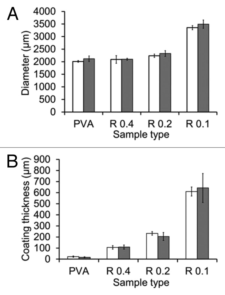
Figure 4. Measurements of diameter (A) and coating thickness (B) for each type of samples
Higher magnitude observations were performed using low vacuum SEM, for which hydrated samples can be observed without any metallization and for a few minutes before the effect of water evaporation distorts the microstructure of hydrogel samples. A series of observations in secondary electron mode is given in the first two columns of Figure 5 for PVA and PVA/HA coated samples. For PVA coated samples, both cross-section (Fig. 5A) and surface (Fig. 5B) views indicate that the PVA coating fits the bundle closely. At this scale, the coating looks uniform and no cracks are visible at the surface. For PVA/HA coated samples, cross-section observations in Figure 5D, G, and J show a homogeneous and dense packing of HA particles along the coating thickness for all values of R. HA particles are glued together by the PVA matrix and no particle has passed through the fibers. Surface observations in Figure 5E, H, and K confirm that HA particles are well spread at the surface. All three coatings could withstand drying and no crack was noticed at the surface.

Figure 5. SEM observations of the cross-sections and surfaces of PVA coated (A–C) and PVA/HA coated samples with R = 0.4 (D–F), 0.2 (G–I) and 0.1 (J–L). Images C, F, I, andL show the exact same ROIs as B, E, F, andK using backscattered electron imaging. Scale bar is 100 µm.
Surface observations of the PVA and PVA/HA coatings were also performed using back-scattered electron (BSE) imaging to estimate the exposure of HA at the surface. BSE images are given in Figure 5C, F, I, and L and correspond to the same region of interest as in Figure 5B, E, H, and K, respectively. These observations provide a chemical contrast at the sample surface. In particular, HA particles appear much clearer, almost white, than the PVA matrix covering them. For R = 0.4 as shown in Figure 5E, the quasi-totality of the area is dark, indicating that no HA is directly exposed at the surface. For R = 0.2 and 0.1 as shown in Figure 5I and L, a chemical contrast is observed with white regions corresponding to areas where HA is directly exposed at the surface. For R = 0.2, only some of the particles are uncovered while for R = 0.1, most of HA is directly exposed and it is difficult to distinguish PVA coated regions from shadows caused by surface topography.
These BSE observations provide a quantitative measure of the HA exposure rate. For that, images have been segmented to provide the percentage of white area, as illustrated in the top picture of Figure 6. Two methods were used to determine the threshold as described in the Materials and Methods section and give an upper and a lower bound for the HA surface exposure rate. Estimations of the exposure rate are plotted in Figure 6 as a function of R. For R = 0.4, the percentage of particles exposed at the surface was almost zero. For R = 0.2, the exposure rate is about 30 ± 5% and increases to 55 ± 12% for R = 0.1. These measurements suggest that there is a critical PVA to HA ratio below which HA particles are partially covered by PVA hydrogel and therefore, some direct access to HA is possible at the coating surface. With the studied systems, this critical ratio is in the range 0.4–0.2.
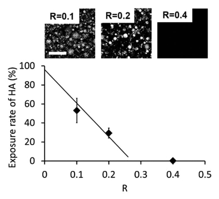
Figure 6. Surface exposure of HA as a function of R. The full line is a linear fit based on data points at R = 0.2 and 0.1, going through full exposure for R = 0. Top images correspond to binarized BSE images used for image analysis. Scale bar is 100 µm.
The stability in water of the coated samples was assessed by storing them in water at room temperature for over 1 y. The implant diameter and the coating thickness remained the same as shown in Figure 4. No microscopic change was observed at the surface. This is consistent with the low solubility of HA and with the stability of physically cross-linked PVA hydrogels, which are known to remain stable in water below 90 °C for highly hydrolyzed PVA grades.29
Resistance to wear and coating cohesion were assessed by a custom fretting experiment where sample surface is in contact with a cylinder of bovine cortical bone as illustrated in Figure 7A. The bone cylinder had a radius of 2.5 mm and fretting occurred by reciprocating motion at 1Hz. Wear was quantified by recording the loss in coating thickness after 1, 10, 50, 100, and 200 cycles as presented in Figure 7B. A decrease in coating thickness was noticed for all samples, except for PVA coated samples. Resistance to wear increases with increasing ratio R, as shown in Figure 7B and C. In particular, after 200 cycles, the loss in coating thickness for the lowest ratio R = 0.1 is three and eight times higher than for R = 0.2 and for R = 0.4 respectively.

Figure 7. Characterization of the coating resistance to wear: (A) Schematic representation of the experimental set up. (B) Worn thickness vs. number of cycles for all sample types; (C) Comparison of surface states before testing and after 100 cycles for R = 0.1 and 0.4. Scale bar is 1 mm.
The strength of the fiber/coating interface was evaluated using pull-out experiments. Threads or bundles of PVA fibers were embedded in a 2 cm-wide bulk cylinder using the same dipping and cross-linking process and the same materials as for the studied coatings. The experiments consisted in measuring the force required to pull these threads or bundles out of the bulk cylinders as illustrated in Figure 8A. A first series of measurements was performed to assess qualitatively the adhesion between the PVA matrix and the PVA fibers. For that, we compared the force required to pull-out a PVA thread and a polyethylene (PE) thread embedded in a bulk PVA cylinder. The corresponding force-displacement curves are given in Figure 8B. For the PVA thread, the thread did not slip immediately out of the cylinder and the force first increased steadily until about 3N. Above 3N, the thread detached abruptly and slipped out of the PVA cylinder. These results strongly suggest that mechanical bonding is formed during the cross-linking process at the interface between the PVA fibers and the PVA coating. For the PE threads, for which no particular bonding with PVA is expected, the thread slipped almost immediately out of the cylinder. The corresponding pull-out force is very weak (<0.5 N) and is most likely caused by friction stresses.

Figure 8. Characterization of the coating adhesion: (A) Schematic representation of the pull out test set up. (B) Force-displacement curves for PVA and PE threads pulled out of a PVA cross-linked matrix. (C) Force-strain curves for PVA pre-coated bundles pulled out of a cross-linked matrix of PVA or PVA/HA (R = 0.2).
In a second series, PVA coated samples were embedded in and pulled out of cylinders of PVA or PVA/HA (R = 0.2). Corresponding force-strain curves are given in Figure 8C. Like for PVA threads, a strong adhesion was observed: for both PVA and PVA/HA cylinders, the samples first deformed without slipping out of the cylinder and extraction occurred above a critical force. The largest forces were required to pull the samples out of the PVA/HA cylinders. The maximum pull-out forces are 25 ± 2 N and 40 ± 2 N for PVA and PVA/HA cylinders, respectively.
The surfaces of samples after pull-out were examined by SEM in low vacuum mode, as shown in Figure 9 for bundles embedded in a PVA and PVA/HA bulk. In all systems, the surface of the extracted samples was covered with bulk matrix. The surface of fibers was not exposed. Cracking occurred in the bulk PVA or PVA/HA material, but not at the interface with the fibers. In addition, cross-section observations in Figure 9B and D show that an intimate contact was conserved between the fibers and the coating after pull-out, meaning that both PVA and PVA/HA coatings are sufficiently bonded to the fibers to withstand the stresses exerted during pull-out.

Figure 9. SEM observations of precoated PVA samples pulled out from a matrix of PVA (A: surface view, B: cross-section) or PVA/HA (C: surface view, D: cross-section). Scale bar is 100µm.
Discussion
The results reported in this study show that a simple dip-coating process can be used to produce composite hydrogel-ceramic coatings for which the surface exposure rate of ceramics is tunable from none to almost full exposure. In order to be relevant for in vivo use, this process has to fulfil a number of requirements including preservation of the control and repeatability over the coating thickness and surface state.
In the studied systems, spherical HA particles were chosen as they are expected to initiate less inflammatory response than irregular and needle-like particles.30 A large range in particle size from 1 to 70µm was used. For such a size range, little inflammatory response has been observed in previous works. In vitro studies by Laquerriere et al.31,32 have shown that large non-phagocytable particles (10–70 µm) do not provoke a strong inflammatory response. For smaller sizes in the range 1–30 µm, they find that some cellular response and inflammatory activity occur and depend also on the shape of the particles. An in vitro and in vivo study by Malard et al.33 has shown that small particles with diameters ranging from 10 to 20 µm induce more inflammatory response than larger ones. Here, the proposed process can easily be revised to use a narrower size range if needed.
The microscopic observations presented here show that both the surface state and the thickness of the coatings are strongly dependent on composition. The surface exposure of HA is mostly governed by the relative content of PVA with respect to HA, as quantified by the weight ratio R. BSE observations indicate that the coating composition must remain below a maximum value of R for HA to be exposed. For our systems, this maximum ratio is of the order of 0.30 ± 0.05 as predicted by a linear fit joining the data points for R = 0.2 and 0.1 to the full exposure at R = 0. This relationship between HA surface exposure and parameter R is most likely related to the wetting of HA particles by hydrated PVA chains, like for the wetting of granular media by polymer binders.34,35 For large values of R, full wetting of HA particles by PVA is obtained and only PVA hydrogel is exposed at the coating surface. As R is reduced, the surface of HA particles is partially wetted by PVA which form capillary bridges between particles: a fraction of HA surface becomes directly exposed at the coating surface. As a consequence, the specific surface area of the HA powder and thus the distribution in particle size should be an additional parameter to tune the exposure rate of HA at the surface of coatings.
Major variations in thickness were also obtained with the three studied compositions: a 6-fold difference was measured between the thinnest (R = 0.4) and thickest (R = 0.1) coating as shown in Figure 4. From predictions of dip-coating models, it is most likely that these large variations are due to changes in the viscosity of the solutions. In particular, if one neglects gravity effects, the Landau-Levich-Derjaguin theory36 predicts that the thickness, e, of a dip-coated film scales as , where V is the substrate extraction velocity, g the gravity constant, η and ρ the viscosity and density of the dipping solution, and γ the surface tension of the air-solution interface. In our case, all samples were extracted at the same velocity. Dipping solutions have similar chemical compositions and their density estimated from Table 1 ranges from 1.2 to 1.6. As a result, effects due to changes in ρ and γ can be reasonably neglected. The solution viscosity η remains the only important governing parameter. Accordingly, qualitative observations of the resistance to mixing confirm that the viscosity of the dipping solutions increases noticeably as R decreases from 0.4 to 0.1. Interestingly, this suggests that the thickness of the coating may be adjusted independently from the surface exposure rate of HA by varying the water content alone.
Dimensional measurements show that a uniform coating thickness can be achieved with this process. However, it might be interesting to produce tapered coatings for which the coating thickness decreases with the bone anchoring distance. In particular, for the anchoring of artificial ligaments, a transition zone from coated to uncoated may be needed at the bone tunnel exit to prevent detachment and migration of HA particles in the intra-articular space. This could be realized here by increasing progressively the extraction velocity or by decreasing the sedimentation speed of HA particles during the dipping step.
The mechanical properties of the composite coatings are also strongly dependent on the relative PVA and HA contents. Fretting experiments on cortical bone reveal strong differences in resistance to wear between the different coating compositions. These differences highlight the mechanical role of the PVA matrix, which is expected to act as a binder providing cohesion to the coating. Accordingly, the results show an 8-fold increase in worn thickness when R decreases from 0.4 to 0.1. Pull-out experiments show how strongly these PVA/HA coatings adhere to PVA based implants. The large difference measured between pull-out resistance of PE and PVA threads (Fig. 8B) suggests that some physico-chemical bonding is created at the interface between the PVA fibers and the PVA coating. This bonding may occur during the freezing-thawing steps when PVA crystallites could form and involve chains from both the fibers and the coating. A similar phenomenon could explain the strong adhesion and fractography observations for PVA coated bundles embedded in PVA or PVA/HA bulk as shown in Figures 9B and D.
These mechanical data provide a guide to assess the performance of these coatings in a putative use as the bone tunnel parts of artificial ligament substitutes. For this type of application, rough contacts occur in multiple situations. The most abrasive contacts are most likely created during the surgery, upon insertion in the bone tunnels and fixation with interference screws. Once the device is implanted, physiological loading of the ligament substitute may also induce fretting wear between the coating and cortical or trabecular bone. Such dynamic conditions may cause the detachment of single particles or coating fragments, which in turn may induce inflammatory response after long-term implantation.37 Coatings with low PVA content (R = 0.1) appear too crumbly to withstand the severe shear caused during bone tunnel insertion.
The in vivo stress state at the bone-coating interface is difficult to evaluate because a large fraction of the load is borne by fixation devices, such as interference screws or endobuttons. An upper bound of the in vivo strain state applied to the interface can be inferred from the maximum tensile strain undergone by native ligaments. Tensile failure occurs between 9 and 60% of strain for both rabbit38 and human ACL.39-41 Pull-out measurements indicate that failure in coated systems with R = 0.2 occurs at similar levels of strain, of the order of 40% (Fig. 8C). This suggests that no decohesion at the fiber-coating interface is expected upon normal in vivo loading. Among the three studied coating compositions, the coating obtained with R = 0.2 offers the best compromise between resistance to wear, coating-fiber adhesion and HA exposure, from the perspective of in vivo implantation in bone.
As regards biocompatibility, no major issue is expected from the composition of matter. For numbers of applications as implants in the osteo-articular system, both PVA and HA have exhibited good biocompatibility.15,22,42,43 For PVA/HA composites, previous in vitro studies using different processes and particle sizes have shown that these systems do not cause a strong inflammatory response44-46 and can even induce differentiation and proliferation of osteoblastic cells.6,8,47 The prior studies do not demonstrate an optimal size, although we suspect grains on the order of 100 microns will leave pores suitable for osteoblast ingrowth. An in vivo study using a subcutaneous murine model by Wang et al.13 have also shown a good tolerance with no cytotoxicity for PVA/HA/gelatin systems having a PVA/HA ratio of 2. Full biocompatibility will require evaluation of the component parts together as an assembly. An in vivo study with appropriate stress and motion will better evaluate the whole device in the anatomic setting with endpoints of local inflammation and hypertrophy.
Conclusion
In this work, we report a simple dip-coating process allowing the fabrication of composite surfaces of ceramic (HA) and hydrogel (PVA), for which the surface exposure of ceramic is tunable. The process is reproducible and does not alter the biocompatibility of the coating. By varying the composition of the dipping solution, the geometry and surface state of the coating can be adjusted over a large range. The viscosity of the solution and the relative content of PVA over HA are the main controlling parameters to tune the coating thickness and the HA surface exposure rate, respectively. In addition, these coatings were found to adhere strongly to PVA fibers which may be used as ligament substitutes.
Materials and Methods
Materials
Commercially available PVA threads (Solvron® MH675, Nitivy Ltd.) were purchased in the form of 15 twisted continuous fibers of 45 dtex each. The PVA used to form these fibers was over 95% hydrolyzed, similar to PVA used in biomedical applications. PVA bundles of about 1.5 mm in diameter were formed by twisting 15 PVA threads following the same protocol as in ref. 27. Embedding and coating of PVA bundles were performed with high molecular weight (89 000–98 000 kg∙mol−1) and 99% hydrolyzed PVA (Sigma-Aldrich). A medical grade powder of hydroxyapatite particles (S.A.I.) was used for the coating with a broad distribution in particle diameter ranging from 5 to 60 µm. Granulometry analysis was done by dry dispersion using a Malvern Mastersizer 3000 particle size analyzer.
Implant fabrication
Preparation of coating solutions
PVA powder was dissolved under mechanical stirring in ultrapure water using a silicon oil bath heated to 110 °C for 15 min to produce a 10 wt% PVA aqueous solution. The weight of the solution was measured after dissolution and water was added to correct from evaporation. The solution was then covered and let cool down and degas.
HA particles were added to the previously prepared PVA aqueous solution and dispersed by mechanical stirring for 5 min. Water content and HA content were adjusted to produce three solutions with different PVA/HA weight ratios as indicated in Table 1. These PVA/HA solutions were then covered and let degas for 3 d.
Coating process
To prevent HA particles from penetrating between fibers, PVA bundles were first embedded in a PVA hydrogel matrix. For that, 10cm PVA bundles were mounted onto stainless steel racks and soaked in the 10 wt% PVA aqueous solution for 1 h. After this time, the racks were taken out of the solution and let drip for 1 min. Cross-linking of the PVA solution covering the bundles was obtained by the freezing/thawing method28 as follows. The racks were placed in a freezer at –20 °C for 19 h and then back to 20 °C for 5 h. This cycle was repeated five times for one of the racks and twice for the rack intended for PVA/HA coating.
The rack of PVA bundles that underwent two freeze/thaw cycles was soaked in the PVA/HA solution for 1 h, taken out, let drip for 1 min and submitted to five additional freeze/thaw cycles to cross-link the HA/PVA coating that covered the samples.
Microscopic characterization
The structure of fabricated samples was characterized by optical microscopy and scanning electron microscopy (SEM) using both secondary electron and backscattered electron detection. Optical microscopy was performed with an Axio Scope A1 Zeiss apparatus on fully hydrated samples immersed in water. Observations were made in dark field reflection mode at a 10× magnification. Dimensional uniformity was assessed by measuring the outer diameter in ten different places along the whole bundle length (5cm). An average coating thickness was estimated using Image J Software from cross-section observation in two different places, by measuring the thickness radially in ten directions. SEM was performed on a Nova Nano SEM 450 SEI apparatus in low-vacuum mode at 90 Pascal and 5 kV. In these conditions, no metallization is required and samples can be observed in a semi-hydrated state for the first ten minutes.
Exposure rate estimation
Exposure rate was estimated by image analysis of BSE images using ImageJ software. On these BSE images, exposed hydroxyapatite appears with a brighter contrast than PVA. As a result, images were binarized and the surface exposure rate was estimated by taking the fraction of white pixels. For each type of coating, the measurement was performed on three images corresponding to a total area of about 0.1 mm2.
Two methods were used to define the threshold for segmentation. In a first method giving a lower bound, a reference threshold was defined on the image having the weakest chemical contrast (R = 0.4) and was applied to the others images. In a second method giving an upper bound, the secondary electron image corresponding to each BSE image was used to find a region showing both covered and uncovered surfaces of HA. The threshold was determined as the best value capturing the boundary between covered and uncovered surfaces.
Pull out experiments
Samples for pull-out tests were obtained by embedding the extremity of a thread or a bundle of fibers in a bulk cylinder of PVA or PVA/HA hydrogels. Embedding was obtained in three steps: (1) the thread or bundle were passed through a cylindrical mold, (2) the mold was filled with a solution of PVA or PVA/HA while holding the thread or bundle in place, (3) the solution of PVA or PVA/HA was cross-linked by a series of five freezing-thawing cycles. Three different threads or bundles were embedded; threads of polyethylene, threads of 15 twisted PVA fibers and bundles of 15 twisted PVA threads, as described in reference 27.
Pull out experiments were performed on a tensile testing apparatus (Instron 5866) using a 500 N load cell. The embedded end of the threads or bundles was hold in a metal holder while the free extremity was attached to the superior grip using capstan knot. Pulling was performed at 0.5 mm/sec until complete extraction from the bulk cylinder. For bundle pull-out, the deformation of the bundle was measured by following the distance between two markers fixed on each bundle.
Wear characterization
Wear experiments were performed at room temperature in wet condition using a CETR UMT-3 tester in cylinder-on-cylinder configuration in reciprocating motion. The upper wearing part is a 10 mm long bone cylinder of 5 mm diameter, obtained from cortical bone of bovine femur. Coated samples are immersed in water and fixed to the lower moving part. Contact between bone and sample is performed by applying an initial normal force of 0.5 N after which normal displacement is fixed. Wear cycles are applied in a reciprocating motion at 1 Hz with a 4 mm amplitude. After 1, 10, 50, 100, and 200 cycles, test was interrupted to create a new contact at 0.5 N and measure the reduction in coating thickness. Surface condition of the sample is also recorded, using Keyence VHX-2000 digital microscope in wet condition.
Disclosure of Potential Conflicts of Interest
No potential conflicts of interest were disclosed.
Acknowledgments
The authors are thankful to Y. Auriac and M. Betbeder (Mines-Paristech) for technical support on mechanical testing and SEM observations, as well as H. Proudhon (Mines-Paristech) for fretting experiments. We also thank Dr. H.Petite, Prof. D.Hannouche, and Prof. V. Viateau (B2OA, University Paris Diderot) for fruitful discussions. Funding by Mines-ParisTech and Institut Carnot-Mines (Project HAP-Process 2012) is gratefully acknowledged.
Glossary
Abbreviations:
- ACL
anterior cruciate ligament
- HA
hydroxyapatite
- PVA
poly(vinyl alcohol)
- SEM
scanning electron microscopy
- SE
secondary electrons
- BSE
backscattered electrons
- PE
poly(ethylene)
References
- 1.Bray RC, Leonard CA, Salo PT. Vascular physiology and long-term healing of partial ligament tears. J Orthop Res. 2002;20:984–9. doi: 10.1016/S0736-0266(02)00012-8. [DOI] [PubMed] [Google Scholar]
- 2.Woo SL, Abramowitch SD, Kilger R, Liang R. Biomechanics of knee ligaments: injury, healing, and repair. J Biomech. 2006;39:1–20. doi: 10.1016/j.jbiomech.2004.10.025. [DOI] [PubMed] [Google Scholar]
- 3.Mascarenhas R, MacDonald PB. Anterior cruciate ligament reconstruction: a look at prosthetics--past, present and possible future. Mcgill J Med. 2008;11:29–37. [PMC free article] [PubMed] [Google Scholar]
- 4.Guidoin MF, Marois Y, Bejui J, Poddevin N, King MW, Guidoin R. Analysis of retrieved polymer fiber based replacements for the ACL. Biomaterials. 2000;21:2461–74. doi: 10.1016/S0142-9612(00)00114-9. [DOI] [PubMed] [Google Scholar]
- 5.Larkin LM, Calve S, Kostrominova TY, Arruda EM. Structure and functional evaluation of tendon-skeletal muscle constructs engineered in vitro. Tissue Eng. 2006;12:3149–58. doi: 10.1089/ten.2006.12.3149. [DOI] [PMC free article] [PubMed] [Google Scholar]
- 6.Hou R, Zhang G, Du G, Zhan D, Cong Y, Cheng Y, Fu J. Magnetic nanohydroxyapatite/PVA composite hydrogels for promoted osteoblast adhesion and proliferation. Colloids Surf B Biointerfaces. 2013;103:318–25. doi: 10.1016/j.colsurfb.2012.10.067. [DOI] [PubMed] [Google Scholar]
- 7.Hayami T, Matsumura K, Kusunoki M, Nishikawa H, Hontsu S. Imparting cell adhesion to poly(vinyl alcohol) hydrogel by coating with hydroxyapatite thin film. Mater Lett. 2007;61:2667–70. doi: 10.1016/j.matlet.2006.10.019. [DOI] [Google Scholar]
- 8.Matsumura K, Hayami T, Hyon SH, Tsutsumi S. Control of proliferation and differentiation of osteoblasts on apatite-coated poly(vinyl alcohol) hydrogel as an artificial articular cartilage material. J Biomed Mater Res A. 2010;92:1225–32. doi: 10.1002/jbm.a.32448. [DOI] [PubMed] [Google Scholar]
- 9.Baxter FR, Bach JS, Detrez F, Cantournet S, Corté L, Cherkaoui M, Ku DN. Augmentation of bone tunnel healing in anterior cruciate ligament grafts: application of calcium phosphates and other materials. J Tissue Eng. 2010;2010:712370. doi: 10.4061/2010/712370. [DOI] [PMC free article] [PubMed] [Google Scholar]
- 10.Pan W, Cao Z, Li D, Zhang M. Evaluation of the potential application of three different biomaterials combined with bone morphological proteins for enhancing tendon-bone integration. Injury. 2013;44:550–7. doi: 10.1016/j.injury.2012.09.019. [DOI] [PubMed] [Google Scholar]
- 11.Li H, Wu Y, Ge Y, Jiang J, Gao K, Zhang P, Wu L, Chen S. Composite coating of 58S bioglass and hydroxyapatite on a poly (ethylene terephtalate) artificial ligament graft for the graft osseointegration in a bone tunnel. Appl Surf Sci. 2011;257:9371–6. doi: 10.1016/j.apsusc.2011.05.110. [DOI] [Google Scholar]
- 12.Hirota M, Hayakawa T, Yoshinari M, Ametani A, Shima T, Monden Y, Ozawa T, Sato M, Koyama C, Tamai N, et al. Hydroxyapatite coating for titanium fibre mesh scaffold enhances osteoblast activity and bone tissue formation. Int J Oral Maxillofac Surg. 2012;41:1304–9. doi: 10.1016/j.ijom.2011.12.035. [DOI] [PubMed] [Google Scholar]
- 13.Wang M, Li Y, Wu J, Xu F, Zuo Y, Jansen JA. In vitro and in vivo study to the biocompatibility and biodegradation of hydroxyapatite/poly(vinyl alcohol)/gelatin composite. J Biomed Mater Res A. 2008;85:418–26. doi: 10.1002/jbm.a.31585. [DOI] [PubMed] [Google Scholar]
- 14.Kopecek J. Hydrogel biomaterials: a smart future? Biomaterials. 2007;28:5185–92. doi: 10.1016/j.biomaterials.2007.07.044. [DOI] [PMC free article] [PubMed] [Google Scholar]
- 15.Kobayashi M, Chang YS, Oka M. A two year in vivo study of polyvinyl alcohol-hydrogel (PVA-H) artificial meniscus. Biomaterials. 2005;26:3243–8. doi: 10.1016/j.biomaterials.2004.08.028. [DOI] [PubMed] [Google Scholar]
- 16.Maher S, Doty SB, Torzilli P, Thornton S, Lowman A. M, Thomas J. D. Warren R., Wright T. M, Myers E. Nondegradable hydrogels for the treatment of focal cartilage defects. J Biomed Mater Res. 2007;83A:145–55. doi: 10.1002/jbm.a.31255. [DOI] [PubMed] [Google Scholar]
- 17.Poursamar SA, Azami M, Mozafari M. Controllable synthesis and characterization of porous polyvinyl alcohol/hydroxyapatite nanocomposite scaffolds via an in situ colloidal technique. Colloids Surf B Biointerfaces. 2011;84:310–6. doi: 10.1016/j.colsurfb.2011.01.015. [DOI] [PubMed] [Google Scholar]
- 18.Sinha A, Guha A. Biomimetic patterning of polymer hydrogels with hydroxyapatite nanoparticles. Mater Sci Eng C. 2009;29:1330–3. doi: 10.1016/j.msec.2008.10.024. [DOI] [Google Scholar]
- 19.Suetsugu Y, Walsh D, Tanaka J, Mann S. Hydroxyapatite pattern formation in PVA gels. J Mater Sci. 2009;44:5806–14. doi: 10.1007/s10853-009-3815-y. [DOI] [Google Scholar]
- 20.Tadavarthy SM, Moller JH, Amplatz K. Polyvinyl alcohol (Ivalon)--a new embolic material. Am J Roentgenol Radium Ther Nucl Med. 1975;125:609–16. doi: 10.2214/ajr.125.3.609. [DOI] [PubMed] [Google Scholar]
- 21.Hassan CM, Peppas NA. Structure and application of poly(vinyl alcohol) hydrogels produced by conventional crosslinking or by freezing/thawing methods. Adv Polym Sci. 2000;153:38–65. doi: 10.1007/3-540-46414-X_2. [DOI] [Google Scholar]
- 22.Baker MI, Walsh SP, Schwartz Z, Boyan BD. A review of polyvinyl alcohol and its uses in cartilage and orthopedic applications. J Biomed Mater Res B Appl Biomater. 2012;100:1451–7. doi: 10.1002/jbm.b.32694. [DOI] [PubMed] [Google Scholar]
- 23.Sathe RD, Ku DN. Flexible Prosthetic Vein Valve. J. med. Devices. 2007;1:105–12. doi: 10.1115/1.2736393. [DOI] [Google Scholar]
- 24.Bertazzo S, Zambuzzi WF, Campos DD, Ogeda TL, Ferreira CV, Bertran CA. Hydroxyapatite surface solubility and effect on cell adhesion. Colloids Surf B Biointerfaces. 2010;78:177–84. doi: 10.1016/j.colsurfb.2010.02.027. [DOI] [PubMed] [Google Scholar]
- 25.Dalby MJ, Di Silvio L, Harper EJ, Bonfield W. Increasing hydroxyapatite incorporation into poly(methylmethacrylate) cement increases osteoblast adhesion and response. Biomaterials. 2002;23:569–76. doi: 10.1016/S0142-9612(01)00139-9. [DOI] [PubMed] [Google Scholar]
- 26.Draenert M, Draenert A, Draenert K. Osseointegration of hydroxyapatite and remodeling-resorption of tricalciumphosphate ceramics. Microsc Res Tech. 2013;76:370–80. doi: 10.1002/jemt.22176. [DOI] [PubMed] [Google Scholar]
- 27.Bach JS, Detrez F, Cherkaoui M, Cantournet S, Ku DN, Corté L. Hydrogel fibers for ACL prosthesis: design and mechanical evaluation of PVA and PVA/UHMWPE fiber constructs. J Biomech. 2013;46:1463–70. doi: 10.1016/j.jbiomech.2013.02.020. [DOI] [PubMed] [Google Scholar]
- 28.Hassan CM, Peppas NA. Cellular PVA Hydrogels Produced by Freeze/Thawing. J Appl Polym Sci. 2000;76:2075–9. doi: 10.1002/(SICI)1097-4628(20000628)76:14<2075::AID-APP11>3.0.CO;2-V. [DOI] [Google Scholar]
- 29.Hassan CM, Peppas NA. Structure and Morphology of Freeze/Thawed PVA Hydrogels. Macromolecules. 2000;33:2472–9. doi: 10.1021/ma9907587. [DOI] [Google Scholar]
- 30.Laquerriere P, Grandjean-Laquerriere A, Jallot E, Nardin M, Frayssinet P, Nedelec JM, Laurent-maquin D. Effect of the physicochemical characteristics of hydroxyapatite on the cell behavior. ITBM-RBM. 2005;26:200–5. doi: 10.1016/j.rbmret.2005.04.007. [DOI] [Google Scholar]
- 31.Laquerriere P, Grandjean-Laquerriere A, Jallot E, Balossier G, Frayssinet P, Guenounou M. Importance of hydroxyapatite particles characteristics on cytokines production by human monocytes in vitro. Biomaterials. 2003;24:2739–47. doi: 10.1016/S0142-9612(03)00089-9. [DOI] [PubMed] [Google Scholar]
- 32.Laquerriere P, Grandjean-Laquerriere A, Kilian L, Beorchia A, Guenounou M, Jallot E, Balossier G, Frayssinet P. Influence of hydroxyapatite particle characteristics on the [K]/[Na] ratio: a human monocytes in vitro study. Colloid surface B Biointerfaces. 2004;33:39–44. doi: 10.1016/j.colsurfb.2003.08.012. [DOI] [Google Scholar]
- 33.Malard O, Bouler JM, Guicheux J, Heymann D, Pilet P, Coquard C, Daculsi G. Influence of biphasic calcium phosphate granulometry on bone ingrowth, ceramic resorption, and inflammatory reactions: preliminary in vitro and in vivo study. J Biomed Mater Res. 1999;46:103–11. doi: 10.1002/(SICI)1097-4636(199907)46:1<103::AID-JBM12>3.0.CO;2-Z. [DOI] [PubMed] [Google Scholar]
- 34.Megias-Alguacil D, Gauckler LJ. Accuracy of the toroidal approximation for the calculus of concave and convex liquid bridges between particles. Granul Matter. 2011;13:487–92. doi: 10.1007/s10035-011-0260-9. [DOI] [Google Scholar]
- 35.Mitarai N, Nakanishi H. Simple model for wet granular materials with liquid clusters. EPL 2009; 88: 6pp. [Google Scholar]
- 36.Landau LD, Levich LD. Dragging of a liquid by a moving plate. Acta Physicochim. USSR. 1942;17:42–54. [Google Scholar]
- 37.Morscher EW, Hefti A, Aebi U. Severe osteolysis after third-body wear due to hydroxyapatite particles from acetabular cup coating. J Bone Joint Surg Br. 1998;80:267–72. doi: 10.1302/0301-620X.80B2.8316. [DOI] [PubMed] [Google Scholar]
- 38.Yamamoto S, Saito A, Nagasaka K, Sugimoto S, Mizuno K, Tanaka E, Kabayama M. The strain-rate dependence of mechanical properties of rabbit knee ligaments. Proceedings of the 18th International Technical Conference on the Enhanced Safety of Vehicles (ESV) 2003. [Google Scholar]
- 39.Butler DL, Kay MD, Stouffer DC. Comparison of material properties in fascicle-bone units from human patellar tendon and knee ligaments. J Biomech. 1986;19:425–32. doi: 10.1016/0021-9290(86)90019-9. [DOI] [PubMed] [Google Scholar]
- 40.Noyes FR, Grood ES. The strength of the anterior cruciate ligament in humans and Rhesus monkeys. J Bone Joint Surg Am. 1976;58:1074–82. [PubMed] [Google Scholar]
- 41.Takeda Y, Xerogeanes JW, Livesay GA, Fu FH, Woo SL. Biomechanical function of the human anterior cruciate ligament. Arthroscopy. 1994;10:140–7. doi: 10.1016/S0749-8063(05)80081-7. [DOI] [PubMed] [Google Scholar]
- 42.Surmenev RA, Surmeneva MA, Ivanova AA. Significance of calcium phosphate coatings for the enhancement of new bone osteogenesis--a review. Acta Biomater. 2014;10:557–79. doi: 10.1016/j.actbio.2013.10.036. [DOI] [PubMed] [Google Scholar]
- 43.Faig-Martía J, Gil-Murb F. Hydroxyapatite coatings in prosthetic joints. Rev Esp Cir Ortop Traumatol. 2008;52:113–20. [Google Scholar]
- 44.Nie L, Chen D, Suo J, Zou P, Feng S, Yang Q, Yang S, Ye S. Physicochemical characterization and biocompatibility in vitro of biphasic calcium phosphate/polyvinyl alcohol scaffolds prepared by freeze-drying method for bone tissue engineering applications. Colloids Surf B Biointerfaces. 2012;100:169–76. doi: 10.1016/j.colsurfb.2012.04.046. [DOI] [PubMed] [Google Scholar]
- 45.Chang W, Mu X, Zhu X, Ma G, Li C, Xu F, Nie J. Biomimetic composite scaffolds based mineralization of hydroxyapatite on electrospun calcium-containing poly(vinyl alcohol) nanofibers. Mater Sci Eng C Mater Biol Appl. 2013;33:4369–76. doi: 10.1016/j.msec.2013.06.023. [DOI] [PubMed] [Google Scholar]
- 46.Costa H, Mansur A, Barbosa-Stancioli E, Pereira M, Mansur H. Morphological, mechanical, and biocompatibility characterization of macroporous alumina scaffolds coated with calcium phosphate/PVA. J Mater Sci. 2008;43:510–24. doi: 10.1007/s10853-007-1849-6. [DOI] [Google Scholar]
- 47.Wu G, Su B, Zhang W, Wang C. In vitro behaviors of hydroxyapatite reinforced polyvinyl alcohol hydrogel composite. Mater Chem Phys. 2008;107:364–9. doi: 10.1016/j.matchemphys.2007.07.028. [DOI] [Google Scholar]