Abstract
The use of a craniotomy for in vivo experiments provides an opportunity to investigate the dynamics of diverse cellular processes in the mammalian brain in adulthood and during development. Although most in vivo approaches use a craniotomy to study brain regions located on the dorsal side, brainstem regions such as the pons, located on the ventral side remain relatively understudied. The main goal of this protocol is to facilitate access to ventral brainstem structures so that they can be studied in vivo using electrophysiological and imaging methods. This approach allows study of structural changes in long-range axons, patterns of electrical activity in single and ensembles of cells, and changes in blood brain barrier permeability in neonate animals. Although this protocol has been used mostly to study the auditory brainstem in neonate rats, it can easily be adapted for studies in other rodent species such as neonate mice, adult rodents and other brainstem regions.
Keywords: Neuroscience, Issue 87, auditory system; blood brain barrier permeability; development; neurophysiology; two-photon microscopy, electrophysiology,
Introduction
The use of a craniotomy in combination with fluorescence imaging and electrophysiology techniques allows monitoring blood flow, blood brain barrier permeability and measuring the activity of neurons and glial cells in live animals1-3. Several laboratories have used this approach to provide insight into brain physiology in healthy and disease conditions, but gaps remain in our understanding of how these processes arise during development. Furthermore, most studies have focused on brain regions that are readily accessible from the dorsal surface of the skull, such that ventral brainstem structures with diverse physiological roles have been studied mostly using ex vivo approaches.
The main goal of this protocol is to provide a method for opening a craniotomy on the ventral skull of rodents. This approach was adapted from classic studies performed in larger mammals such as dogs and cats for sensory neurophysiology recordings of the auditory brainstem4-7. In this protocol however, there is the novel challenge of performing the procedure in neonate animals. Using vasculature landmarks, this adapted protocol has been used previously to study the auditory brainstem of neonate rats, adult mice and other brainstem regions like the inferior olive8-11 (Figure 1).
A main advantage of a ventral craniotomy over existing methods to study ventral brainstem nuclei is that it provides direct access to the structures of interest in living animals. For example, the auditory cells of the superior olivary complex are localized a few tens of micrometers from the brain surface, which is important for targeted placement of probes and for using two-photon imaging approaches in which imaging depth can be limited to 0.5 mm by light tissue scattering and absorption. A ventral craniotomy also provides a preparation with relatively intact neural connections, which are disrupted in acute and organotypic slice preparations12. In contrast to other protocols for in vivo neurophysiology experiments13, a ventral approach can be combined with multi-electrode recording and imaging methods that provide information about cellular ensembles (Figures 6 and 7). Lastly, in combination with this protocol a fluorescently labeled solute can be injected in the vasculature to measure changes in blood brain barrier permeability to the solute (Figure 8).
Protocol
The following protocol follows the animal care guidelines established by the Institutional Animal Care and Use Committee (IACUC) at The City College of New York.
1. Animal Intubation (10-20 min)
- Prior to surgery, prepare mammalian Ringer solution. Assemble the surgical tools, heating pad, and small animal ventilator on the bench (Figure 2).
- For measurements of blood brain barrier permeability make 10 ml of 1% bovine serum albumin (BSA) solution in Ringer and dissolve TRITC-dextran 155 kD at 8 mg/ml in 1% BSA solution, filter solution with 25 mm syringe filter (0.2 μm pore size) and store in a foil-covered syringe in the dark.
- Anesthetize the animal using isoflurane. Use 5.0% for induction and 1.5-3.0% for maintenance. Alternatively a mixture of ketamine (41.7 mg/kg) and xylazine (2.5 mg/kg body) can be used. Depth of anesthesia can be checked by toe pinch reflex of upper and lower extremities.
- Subsequent doses of ketamine (41.7 mg/kg body weight) and xylazine (2.3 mg/kg body weight) should be administered in increments of ⅓ of the maximum dose to avoid overdosing. Use of a rodent ventilator is recommended to counteract xylazine-induced respiratory depression.
- Place the anesthetized pup lying on its dorsal side and secure its head with the plastic cone used to deliver the anesthetic (Figure 3a).
- Secure the animal with adhesive tape on the fore limbs and tail (Figure 3a).
- An alternative to secure the pup’s head is to use a head plate attached to a metal bar. Note: Make sure the heating pad is set to 37 °C to avoid hypothermia (Figure 3a).
- Use scissors (Figure 2b) to make one longitudinal and four lateral incisions on the skin overlying the neck (Figure 3b). Using blunt technique, dissect the skin and place it aside using forceps (Figures 2c and 3c).
- Hold the skin down using adhesive tape. Stabilize the head in a horizontal position (Figure 3c).
- Using spring scissors (Figure 2d) and blunt technique, push glands and fat layers aside to expose the trachea (Figure 3c). Identify the location of the carotid arteries.
- Keep the carotid arteries away from the trachea. Note: Puncturing the carotids can result in massive blood loss and death of the pup.
- Using spring scissors (Figure 2d) dissect the longitudinal muscles covering the trachea. Cut the longitudinal muscles located under the trachea (Figure 3d). Note: The tracheal rings should be clearly visible (Figure 3e).
- Using forceps (Figure 2c), tie two pieces of suture around the trachea. One piece of suture will secure the ventilation tube and the second thread will be used to close the trachea rostral to the ventilation tube insertion point (Figure 4a). Note: Moisten exposed tissue regularly with Ringer solution to prevent dehydration.
Using spring scissors (Figure 2d) make an incision on one of the tracheal rings located between the two threads placed in step 1.6.1 (Figure 4c). Note: Make sure that no fluid enters the open trachea. Fluid in the trachea will cause asphyxiation.
- Insert the intubation tube (Figure 4b) into the trachea and tighten the lower thread to secure it. Using forceps (Figure 2c), tighten the upper thread to close the trachea posterior to the insertion point of the intubation tube.
- Tighten and trim the ends of the two threads (Figure 4d-f). Note: Vapor inside the intubation tube is a good sign of airflow control.
- Promptly switch the isoflurane supply to the ventilator. Adjust the stroke volume and the ventilation rate according to the weight of the animal.
- Seal the exposed surrounding tissue with elastomer (Figure 5a). Keep the surface moistened and clean.
2. Trachea and Muscle Removal to Expose the Cranium (5-10 min)
Use spring scissors (Figure 2d) to cut the trachea adjacent to the ventilation tube. Perform two cuts along the muscle wall of the buccal cavity to expose the caudal end of the palate (Figure 5b). Note: If necessary, use a cauterizer to stop bleeding. Uncontrolled bleeding will cause death of the animal.
Clean the area using copious amounts of Ringer solution (Figure 5c). Identify the gap between the last vertebrae and the basi-occipital bone (Figure 5d). Note: The gap between the bones is a useful skull landmark to locate brainstem structures. The inferior olive is located under this gap. The auditory superior olivary complex is located under the basi-occipital bone in the rostral direction from this gap (see also Figure 1).
- Clean the area using forceps (Figure 2c) and spring scissors (Figure 2d). Do not puncture blood vessels. Note: If necessary, cauterize to stop bleeding.
- After the exposed area is clean of fat and muscle tissue, the space separating the basi-occipital bone and the last vertebra should be visible (Figure 5d).
3. Craniotomy (15-30 min)
- Use a microdrill or an ultrasonic cleanser. Locate the medial wall of the bulla.
- Thin the skull by making an inverted D shape until the underlying arteries are visible (Figure 5e). Note: The basilar artery (bas) runs on top of the brainstem midline. The anterior inferior cerebellar artery (aica) branches bilaterally and can be used reliably as a landmark as it has a constant position in different animals.
- When the skull is thinned, gently break it using a dissecting chisel (Figure 2e). Remove the bone piece with forceps (Figure 2c). Alternatively, lift and break the skull using a bent needle. Note: Repeat this procedure until the size and shape of the craniotomy is appropriate for the planned experiment. The bas and aica should be visible through the dura membrane (Figure 5f).
- Clean the area several times with fresh Ringer solution. Using absorbent pads dry the surface of the dura membrane.
- If necessary, use a suture needle to remove the dura membrane without displacing or breaking the landmark arteries bas and aica. Note: Upon dura puncturing cerebrospinal fluid will flow out. Clean the area with Ringer solution and keep moistened throughout the experiment.
4. Electrophysiology Experiment
- Select the polytrode according to experiment design (Figure 7a). Use a fine paintbrush to coat the polytrode with DiI. Transfer the DiI solution into a 1 ml microcentrifuge tube, dip the paintbrush in the solution and gently strike the polytrode under visual guidance (i.e. using a stereoscope). Start at the tip of the probe and carefully continue until all electrodes are coated uniformly.
- Place the ground electrode inside the oral cavity. Load the polytrode into the electrode holder (Figure 7b).
- Turn the amplifier on and check that all connections work well.
- Position the electrode above bas at the branch point of aica (position zero). Move the electrode to the desired target point by using the appropriate rostral-lateral coordinate (Figure 7c).
- Place the electrode on the brain surface and move it to the desired depth in steps of 5-10 μm.
Perform recording according to experimental design. Save data for further analysis.
5. Two-photon Imaging Experiment
Turn on the microscope. Set the excitation wavelength and use an appropriate emission filter. Excitation at 800 nm and a 607 ± 45 nm band-pass emission filter work well for imaging TRITC-dextran.
- Identify the right or left carotid artery. Using blunt technique dissect the carotid artery from the adjacent connective tissues or nerves.
- Pick and hold the carotid artery with a hemostat. Tie three pieces of suture around the carotid artery.
- Tighten the thread closer to the heart side to stop the blood flow and leave the other two threads loose.
- Use fine scissors to make a small cut at a 45° angle on the carotid artery between the tied thread and the next loose thread. Note: Clean the blood with absorbent paper.
- Cannulate the carotid artery. Insert the tubing filled up with TRITC-dextran solution into the cut on the carotid artery about 5 mm deep oriented towards the pup’s head.
- Tighten the other two threads around the artery to hold the tubing and the artery together. Tighten the threads, trim and add elastomer to further stabilize. Note: The other side of the tubing is connected with the syringe containing TRITC-dextran solution (prepared in step 1.1).
- Fix the syringe on the syringe pump.
- Set the speed at the carotid artery blood flow rate of the pup. Turn on the syringe pump for a few seconds and check manually that the dye solution can be injected into the carotid artery. Note: Assuming that blood flow rate in the carotid artery of adult rats (240-280 g) is about 3 ml/min14, the blood flow rate for a rat pup (e.g. P10 pup weighing 15-25 g) can be calculated to range from 0.16-0.3 ml/min.
- Place the animal under the microscope objective. Inject the fluorescent dextran into the bloodstream.
- Identify areas of interest on the ventral brainstem with a 5X air objective. Switch to a 20X or 40X objective (water immersion, NA = 0.5 or 0.8, respectively) to focus the region of interest (ROI).
- Start imaging and adjust the image acquisition parameters (e.g. exposure time, laser power, detector gain) until the fluorescence intensity in the vasculature of the ROI is optimized (i.e. not too low but not to saturated).
- Turn on the syringe pump to inject the dye solution into the carotid artery and acquire a time series at a fixed focal plane.
6. Animal Care Following Procedure
This is a terminal procedure. At the end of an experiment animals must be euthanized with an overdose of Pentobarbital (100 mg/kg, intraperitoneal injection) or any other method of euthanasia approved by American Veterinary Medical Association Euthanasia Guidelines. Note: Perfusion through the heart with Ringer solution followed with a fixative solution is recommended for further histological analysis.
Representative Results
Electroporation of neural tracers
The medial nucleus of the trapezoid body (MNTB) is a group of cells in the superior olivary complex that has been studied previously using this protocol. For example, patch clamp pipettes can be used to electroporate neural tracers (Figure 6)9. When pipettes are placed near the midline as shown in Figure 6a, the result is that decussating afferent axons are labeled. A two-photon microscope equipped with a high numerical aperture water immersion objective can be used to image the fibers reaching the MNTB, including very fine collateral branches (arrows in Figure 6b). Neural tracers can also be delivered to the MNTB directly, as shown in Figure 6c. The result is labeling of MNTB cells and afferent axons, as can be appreciated by imaging with a lower numerical aperture water immersion objective (Figure 6d). The main advantage of using the lower magnification objective is that a wider field of view can be examined, and although this results in a decrease in spatial resolution due to the lower objective numerical aperture, individual MNTB cells can be discerned well (arrows in Figure 6d). The average duration of these experiments for ages P1-P5 is 3.1 ± 1.4 hr (n = 22 pups).
Electrophysiology recordings
Spontaneous burst firing is a form of developmental electrical activity observed in single MNTB cells before the onset of hearing11,13. Using this surgical protocol it is also possible to target multielectrode arrays (polytrodes) to the MNTB (Figure 7a-b). The result is a recording of spontaneous activity in an ensemble of MNTB cells. Figure 7e shows a representative polytrode recording from a P6 rat. In this experiment, the polytrode was coated with the lipophylic dye DiI using a thin paintbrush (see step 4.1). After performing the recording the brain was processed for histological analysis and the location of the DiI-labeled polytrode track was used to confirm proper targeting to the MNTB (Figure 7d). The average duration of experiments for ages P1-P6 is 2.0 ± 0.7 hr (n = 33 pups).
Measuring microvessel permeability
This protocol can also be used to perform two-photon imaging experiments of vascular permeability. A fluorescent solute (TRITC-dextran, MW 155 kD, Stokes radius ~8.5 nm) was dissolved in 1% BSA Ringer solution and injected into the cerebral circulation via a canula inserted in the carotid artery14. Unlike tail vein injections, this procedure bypasses the heart and introduces the fluorescent solute directly into the brain microcirculation. Figure 8a illustrates the quality of labeling of blood vasculature that results from using this procedure. After continuous perfusion of labeled solutes into the blood stream it is possible to obtain a time-lapse sequence of a region of interest, as shown in Figure 8b. The total fluorescence intensity in the region of interest was measured offline and a mathematical model used to determine the blood brain barrier permeability to fluorescently labeled solutes (Figure 8c)15. The average duration of experiments for ages P9-P10 is 2.3 ± 0.8 hr (n = 3 pups).
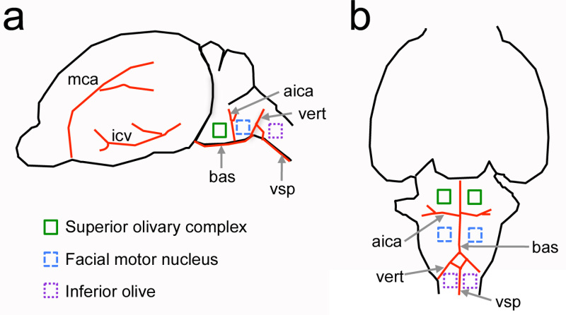 Figure 1. Relative location of ventral brainstem neural structures with respect to vasculature landmarks in the neonate rat.
a, Side view of the brain. b, ventral view of the brain. Major blood vessels are shown in red and neural structures of interest are indicated by color squares. Not drawn to scale. aica = anterior inferior cerebellar artery; bas = basilar artery; icv = inferior cerebral vein; mca = middle cerebral artery; vert = vertebral artery; vsp = ventral spinal artery. Click here to view larger image.
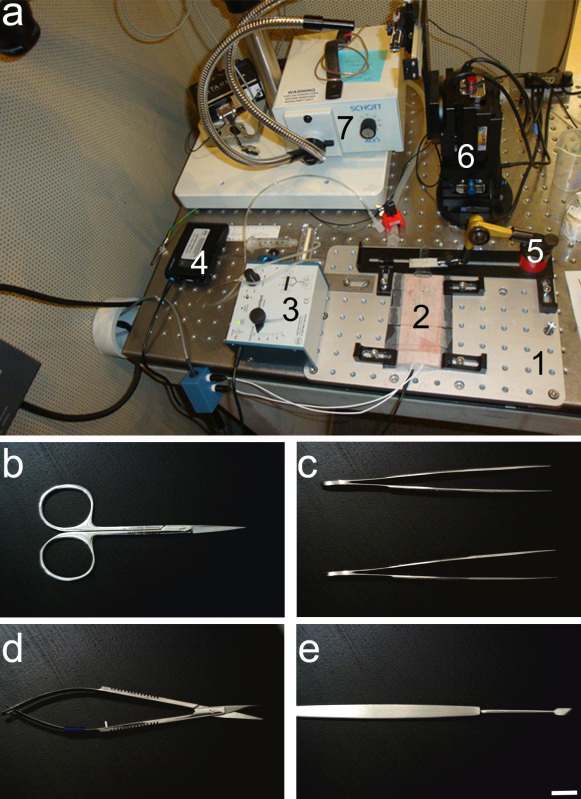 Figure 2. Surgical setup.a, Surgery can be done on a small bread board (1) resting on top of a stable table top. A heating pad (2) and a small animal ventilator (3) can be fastened to the bread board to facilitate moving the entire preparation when needed. The small animal ventilator can be powered by a battery (4). A magnetic holder (5) can be used to secure the nose cone used to deliver the anesthetic. The nose cone can also help secure the head in a stable position. If the animal does not need to be relocated, a micromanipulator (6) can be used to position probes for electrophysiology or neural tracing experiments. A light source (7) and a stereoscope (not pictured) are necessary to visualize landmark structures during microsurgery. b, Small scissors are used in step 1.4. c, Forceps are used in steps 1.4, 1.6.1, 1.8 and 1.8.1. d, spring scissors are used in steps 1.5, 1.6 and 1.7. e, dissecting chisel is used in step 3.1.2. Scale bar in e = 1 mm, applies to b-d. Click here to view larger image.
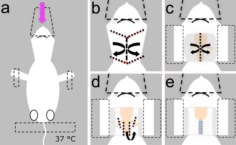 Figure 3. Exposing the trachea for intubation.a, The animal is anesthetized, placed in the prone position and secured with the nose cone and tape (dashed lines). b, The skin is cut and placed aside to expose the underlying fat layer. c, The overlying fat and glands (shown in grey) are pushed aside to expose the trachea. Tape is used to secure the overlying skin (dashed lines). d, The trachea is dissected from the musculature. e, Visualization of tracheal rings indicates successful removal of overlying muscle. Click here to view larger image.
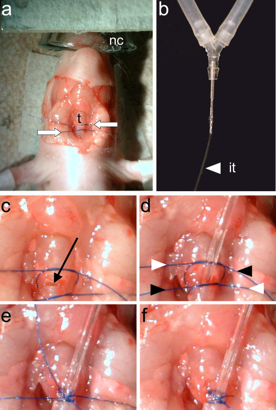 Figure 4. Intubating the animal.a, Two suture threads (white arrows) are tied around the trachea (t). b, The intubation tube (it) must be tightly connected to the y tube of the animal ventilator. c, A tracheostomy is made between the two suture threads (black arrow). d, The ventilation tube is inserted and the two suture threads are tightened. The ends of the threads are tightened again in a crossed fashion (indicated by white and black arrowheads). e, The suture endings are tied. f, The suture endings are trimmed and intubation is complete. Click here to view larger image.
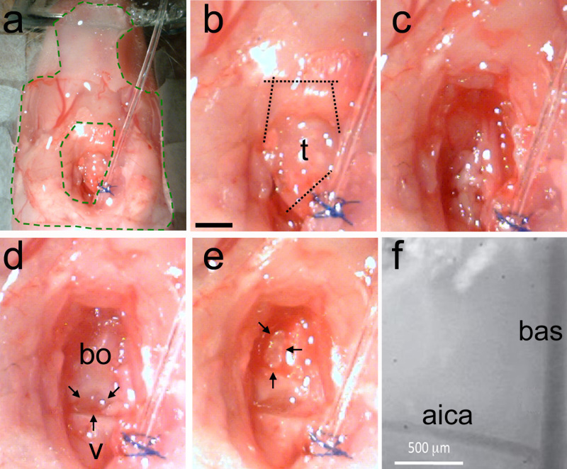 Figure 5. Removing the trachea and making the craniotomy.a, The preparation is stabilized with elastomer (area inside green dashed lines). b, The trachea is identified and then cuts are made first to separate the trachea away from the intubation tube, and then to cut the mandibular muscles (dotted lines). c, Clean the surface of the skull using blunt technique to remove muscle and use absorbent paper to remove fat and blood. d, Example of a clean area shows the last vertebrae (v) and the basi-occipital bone (bo). There is a natural gap between the two bones (black arrows). e, Using a microdrill or ultrasonic cleanser thin the skull in an inverted D shape (black arrows). Gently break the thinned skull and remove the piece of bone. Landmark vasculature should be visible. f, High-magnification view of vascular landmarks on the exposed brainstem surface. Bas = basilar artery; aica = anterior inferior cerebellar artery. Scale bar in b = 1 mm, applies to c-e. Click here to view larger image.
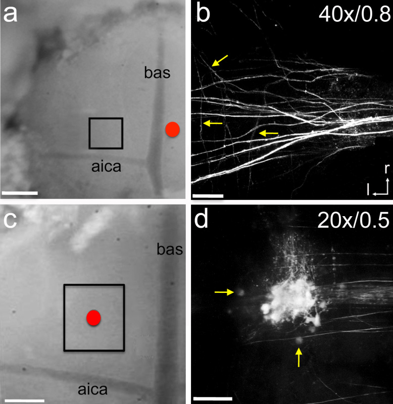 Figure 6. Electroporation of neural tracers.a, A glass electrode containing the neural tracer micro-ruby was placed near the midline (red circle). The tracer was electroporated using 7 second long -5 μA pulses delivered every 14 seconds for 15 minutes. After 1 hour of recovery time the boxed area was imaged with a two-photon microscope. P1 rat pup. b, Exemplar z-stack image of afferent axon labeling in the MNTB. Arrows point to individual collateral branches. c, A glass electrode filled with micro-ruby was positioned on top of the MNTB (red circle). The tracer was electroporated using the same settings described in a. After 1 hour of recovery time the boxed area was imaged with a two-photon microscope. P5 rat pup. d, Exemplar z-stack image of labeled cells and axons in the MNTB. Arrows indicate single MNTB cells. Labels in b and c indicate objective magnification and numerical aperture, respectively. Scale bar in a and c = 300 μm; scale bar in b = 45 μm; scale bar in d = 90 μm. aica = anterior inferior cerebellar artery; bas = basilar artery; r = rostral; l = lateral. Click here to view larger image.
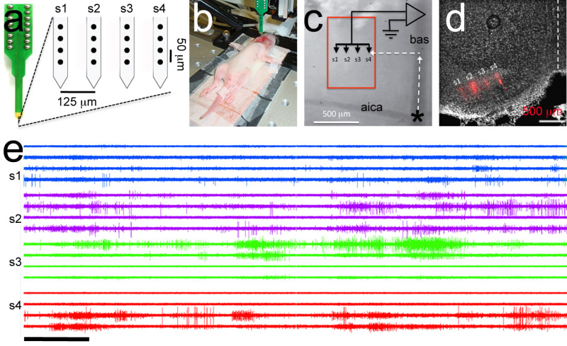 Figure 7. Targeted polytrode recording.a, Polytrode consists of 4 shanks with 4 electrodes per shank (black circles). Intra- and inter-shank distances between electrodes are indicated. b, Exemplar image of electrophysiology experiment. A reference electrode is inserted in the bucal cavity and a ploytrode is connected to the headstage. P6 rat pup. c, Higher magnification view of vasculature landmarks used for polytrode targeting. The polytrode is positioned using rostral-lateral coordinates to target the medial nucleus of the trapezoid body (red box). d, Posthoc histological analysis demonstrates correct targeting of the DiI-coated polytrode (polytrode track is shown in red). e, Exemplar multi-unit recording. Trace order is the same as electrode order in panel a. Within shank recordings have the same color. Scale bar in e = 5 seconds. Click here to view larger image.
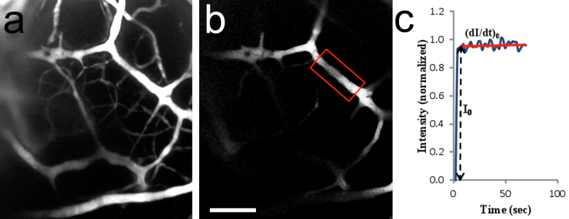 Figure 8. In vivo two-photon imaging of brain microvessels. a, 2-D image (collapsed Z-stack) of brain vasculature after perfusion of TRITC-dextran 155 kD into the carotid artery. The area imaged is similar to that shown in Figure 7c. 20x/0.5 water immersion objective. P10 rat pup. b, Region of interest (ROI) used to measure fluorescence intensity (red frame enclosed region). The microvessel had a diameter of ~14.2 μm and was located 182 μm below the brainstem surface. c, Typical curve of fluorescence intensity (normalized value) as a function of time. I0 is the step increase in fluorescence intensity in the ROI when the fluoresence solution just fills up the vessel lumen. (dI/dt)0 and I0 are used to determine the microvessel permeability to the solute. The permeability to TRITC-dextran 155 kD was calculated to be 1.5 x 10⁻⁷ cm/sec. Scale bar in b = 100 μm, applies to a. Click here to view larger image.
Discussion
Time is critical. An experienced researcher should be able to complete this protocol in 1 hour (steps 1-3). The times stated for the different steps assume a medium to high level of expertise. Proper and timely tracheotomy and intubation are critical, since poor ventilation control can lead to asphyxiation and death of the animal. Careful clearance of muscle and fat tissues is also very important because mistakes can lead to uncontrolled bleeding and death of the animal. Similarly, when preparing the carotid artery for canula insertion, one needs to tighten and cut the artery carefully, if the thread knot becomes loose uncontrolled bleeding will take place. Lastly, the craniotomy should be made carefully, without disrupting the vasculature landmarks. Careless removal of the external meningeal layer (dura) can lead to severe bleeding and damage of the arterial supply.
Ventilation settings are chosen according to the age of the animal. Most commercial suppliers provide useful information about such settings. Experiments in rats older than P15 will require use of a large animal ventilator. Adult animals may not need ventilation if anesthetized with ketamine/xylazine, but intubation is recommended to avoid fluid entering the trachea.
One main limitation of this protocol is that experiments can only be performed acutely. In our laboratory we have performed experiments lasting between two and up to ten hours. A second limitation is that experiments have to be performed under anesthesia. Therefore, the choice of anesthetic is an important variable to consider in the planning and design of experiments. A related issue is that neonate animals can be particularly sensitive to overdosing. For example, if choosing ketamine/xylazine mix, calculate the dose based on pup’s weight and administer drugs at ⅓ of the maximum volume. Check the state of the animal every 5-10 minutes by toe pinch response. If using isoflurane, precautions are also needed to maintain a safe environment for the investigator (proper ventilation, and a properly calibrated vaporizer).
The stereomicroscope can be mounted on a flexible holder to adjust viewing angle and facilitate space clearance to place electrodes and relocation of the animal to the two-photon microscope. Use of a battery to power the ventilator can facilitate moving the animal and reduce electrical artifacts during electrophysiology experiments. To this end, a small breadboard (7.5 x 12 inches) can be used to assemble together the ventilator, heating pad and the anesthetized animal (Figure 2a). A useful and important modification to this setup is the addition of a device for monitoring vital signs during surgery. An oxymeter or other analog devices can be used depending on the laboratory budget.
This protocol has been used with electrophysiology and imaging methods, including patch clamp recordings8,10,11, polytrode recordings (Figure 7), and two-photon imaging9 (Figures 6 and 8). One possible future application would be to combine these methods for targeting fluorescently labeled cells for electrophysiological recording16.
New imaging applications also may include 2-D or 3-D time series using two-photon microscopy. For example, using bolus loading of calcium indicators to study the activity of brainstem neuronal and glial cell populations. As shown in Figure 8, a dye solution injected into the blood circulation through the carotid artery can be used to generate high contrast images of the brain vasculature. As the fluorescence dye fills the microvessel lumen and spreads into the surrounding tissue, it can be used not only for calculating the apparent solute permeability of the blood brain barrier but also the solute diffusion coefficient in the brain tissue3. One main reason for injecting the fluorescently labeled solutes via the carotid artery is that the dye solution can directly go to the microvessels in the brain without going to the heart first as in a tail vein injection. This brings at least two advantages. One is that the fluorescence dye concentration in the microvessel lumen can be practically constant if the perfusion rate is fixed at the cannulation site. This ensures accurate determination of the blood-brain barrier permeability. Another is that if a test agent is included in the perfusate, it will directly go to the blood-brain barrier without being diluted or combined with other factors from the body circulation.
New experiments also may take advantage of transgenic animals with genetically encoded fluorescent reporters. This would provide the advantage that fluorescent probes would not need to be loaded in situ (unless the design of the experiment states otherwise), saving time and possibly allowing for more intact preparations (e.g. cranial window17).
Lastly, experiments can be done in other brainstem regions such as the inferior olive or the facial motor nucleus. Knowledge about neuroanatomy and development of specific cellular populations in a given species will be important towards this end, particularly as anatomical landmarks may change as animals grow (Figure 1). We hope this protocol encourages others to study ventral brainstem structures using in vivo electrophysiological and imaging methods.
Disclosures
The authors have nothing to disclose.
Acknowledgments
This work was supported by grant G12-RR003060 from NIH/NCRR/RCMI, grant SC1HD068129 from the Eunice Shriver National Institute of Child Health & Human Development, National Science Foundation CBET 0754158 and PSC-CUNY 62337-00 40 from the City University of New York.
References
- Kerr JND, Denk W. Imaging in vivo: watching the brain in action. Nat. Rev. Neurosci. 2008;9(3):195–205. doi: 10.1038/nrn2338. [DOI] [PubMed] [Google Scholar]
- Sigler A, Murphy TH. In vivo 2-photon imaging of fine structure in the rodent brain: before, during, and after stroke. Stroke. 2010;41(10):117–123. doi: 10.1161/STROKEAHA.110.594648. [DOI] [PubMed] [Google Scholar]
- Shi L, Zeng M, Sun Y, Fu BM. Quantification of blood-brain barrier solute permeability and brain transport by multiphoton microscopy. ASME J. of Biomech. Eng. 2014;136(3):031005–031005. doi: 10.1115/1.4025892. [DOI] [PubMed] [Google Scholar]
- Galambos R, Schwartzkopff J, Rupert A. Microelectrode study of superior olivary nuclei. Am. J. Physiol. 1959;197:527–536. doi: 10.1152/ajplegacy.1959.197.3.527. [DOI] [PubMed] [Google Scholar]
- Goldberg J, Brown PB. Response of binaural neurons of dog superior olivary complex to dichotic tonal stimuli: some physiological mechanisms of sound localization. J. Neurophysiol. 1969;32(4):613–636. doi: 10.1152/jn.1969.32.4.613. [DOI] [PubMed] [Google Scholar]
- Guinan JJ, Guinan SS, Norris BE. Single auditory units in the superior olivary complex I: responses to sounds and classifications based on physiological properties. Intern. J. Neurosci. 1972;4:101–120. [Google Scholar]
- Spirou GA, Brownell WE, Zidanic M. Recordings from cat trapezoid body and HRP labeling of globular bushy cell axons. J. Neurophysiol. 1990;63(5):1169–1190. doi: 10.1152/jn.1990.63.5.1169. [DOI] [PubMed] [Google Scholar]
- Khosrovani S, Der Giessen RSVan, De Zeeuw CI, De Jeu MT. In vivo mouse inferior olive neurons exhibit heterogeneous subthreshold oscillations and spiking patterns. Proc. Natl. Acad. Sci. U.S.A. 2007;104(40):15911–15916. doi: 10.1073/pnas.0702727104. [DOI] [PMC free article] [PubMed] [Google Scholar]
- Rodríguez-Contreras A, Van Hoeve JS, Habets RL, Locher H, Borst JGG. Dynamic development of the calyx of Held synapse. Proc. Natl. Acad. Sci. U.S.A. 2008;105(14):5603–5608. doi: 10.1073/pnas.0801395105. [DOI] [PMC free article] [PubMed] [Google Scholar]
- Lorteije JA, Rusu SI, Kushmerick C, Borst JGG. Reliability and precision of the mouse calyx of Held synapse. J. Neurosci. 2009;29(44):13770–13784. doi: 10.1523/JNEUROSCI.3285-09.2009. [DOI] [PMC free article] [PubMed] [Google Scholar]
- Tritsch NX, Rodríguez-Contreras A, Crins TT, Wang HC, Borst JGG, Bergles DE. Calcium action potentials in hair cells pattern auditory neuron activity before hearing onset. Nat. Neurosci. 2010;13(9):1050–1052. doi: 10.1038/nn.2604. [DOI] [PMC free article] [PubMed] [Google Scholar]
- Tong H, Steinert JR, Robinson SW, Chernova T, Read DJ, Oliver DL, Forsythe ID. J. Physiol. 9. Vol. 588. London: 2010. Regulation of Kv channel expression and neuronal excitability in rat medial nucleus of the trapezoid body maintained in organotypic culture; pp. 1451–1468. [DOI] [PMC free article] [PubMed] [Google Scholar]
- Sonntag M, Englitz B, Kopp-Scheinpflug C, Rübsamen R. Early postnatal development of spontaneous and acoustically evoked discharge activity of principal cells of the medial nucleus of the trapezoid body: an in vivo study in mice) J. Neurosci. 2008;29(30):9510–9520. doi: 10.1523/JNEUROSCI.1377-09.2009. [DOI] [PMC free article] [PubMed] [Google Scholar]
- García-Villalón AL, Roda JM, Alvarez F, Gómez B, Diéguez G. Carotid blood flow in anesthetized rats: effects of carotid ligation and anastomosis. Microsurgery. 1992;13(5):258–261. doi: 10.1002/micr.1920130513. [DOI] [PubMed] [Google Scholar]
- Yuan W, Lv Y, Zeng M, Fu BM. Non-invasive method for the measurement of solute permeability of rat pial microvessels. Microvasc. Res. 2009;77(2):166–173. doi: 10.1016/j.mvr.2008.08.004. [DOI] [PubMed] [Google Scholar]
- Kitamura K, Judkewitz B, Kano M, Denk W, Haüsser M. Targeted patch-clamp recordings and single-cell electroporation of unlabeled neurons in vivo. Nat. Methods. 2008;5(1):61–67. doi: 10.1038/nmeth1150. [DOI] [PubMed] [Google Scholar]
- Mostany R, Portera-Cailliau C. A method for 2-photon imaging of blood flow in the neocortex through a cranial window. J. Vis. Exp. 2008. [DOI] [PMC free article] [PubMed]


