Abstract
Despite the early recognition of the potential of proton imaging to assist proton therapy the modality is still removed from clinical practice, with various approaches in development. For proton-counting radiography applications such as Computed Tomography (CT), the Water-Equivalent-Path-Length (WEPL) that each proton has travelled through an imaged object must be inferred. Typically, scintillator-based technology has been used in various energy/range telescope designs. Here we propose a very different alternative of using radiation-hard CMOS Active Pixel Sensor (APS) technology. The ability of such a sensor to resolve the passage of individual protons in a therapy beam has not been previously shown. Here, such capability is demonstrated using a 36 MeV cyclotron beam (University of Birmingham Cyclotron, Birmingham, UK) and a 200 MeV clinical radiotherapy beam (iThemba LABS, Cape Town, SA). The feasibility of tracking individual protons through multiple CMOS layers is also demonstrated using a two-layer stack of sensors. The chief advantages of this solution are the spatial discrimination of events intrinsic to pixelated sensors, combined with the potential provision of information on both the range and residual energy of a proton. The challenges in developing a practical system are discussed.
1. Introduction
The potential of proton radiotherapy for improved treatment in comparison to photon therapy, has been promised since its first proposal (Wilson 1946). The fraction of radiotherapy treatments that utilize proton therapy is still very small, but with a recent surge in planned or in-construction proton therapy facilities this is likely to change (Goethals and Zimmermann 2013). In any external beam radiotherapy treatment it is critical to ensure that: (1) the patient is positioned correctly; (2) that the target volume and organs-at-risk have not changed or deformed substantially; and (3) that the properties and amount of overlying tissue is known accurately. The cost of failure in any one of these factors is likely to be particularly high in proton therapy, due to the steep dose fall-off at the end of the range and tendency to treat with few fields (Paganetti 2012).
A raft of image-guidance techniques is becoming available in conventional x-ray radiotherapy to control the first two issues (Evans 2008) and treatment planning using x-ray Computed Tomography (CT) scans has the capability of dealing accurately with the last (Yohannes et al 2012). While some of these techniques are applicable to proton therapy the last factor is particularly problematic. X-ray planning CT scanners infer material electron density, whereas proton stopping power is needed for proton therapy planning. The conversion between the quantities introduces uncertainties which can degrade the accuracy of a treatment plan (Yang et al 2012).
The idea of using radiography with protons instead of x-rays for image-guidance and planning is not new. In the 1960s, Cormack considered the possibility of performing CT with protons to reconstruct stopping-power (Cormack 1963). The first proton projection radiographs were obtained as early as the 1970s (Steward and Koehler 1973). A fundamental difficulty, however, is the quasi-continuous scattering of protons as they travel through a material, due to Multiple Coulomb Scattering (MCS) (Hanson 1979). This seriously limits the image resolution in any energy-integrating device that cannot resolve individual protons.
There has been considerable recent interest in the possibilities for proton radiography (Schneider et al 2004, Sadrozinski et al 2013, Civinini et al 2010, Amaldi et al 2013, Rinaldi et al 2013). The true potential is only likely to be reached via event-counting technology. A superior image can be generated through knowledge of: (i) the number of protons hitting a detector and (ii) each proton’s incident position, direction and energy (or range). A variety of technologies have been proposed. Those for measuring the position/direction of the protons have included Multi Wire Proportional Chambers (Hanson 1979), Scintillating Fibre Hodoscopes (Schneider et al 2004), Gas Electron Multiplier detectors (Amaldi et al 2013) and Silicon Strip Detectors (Sadrozinski et al 2013). Previous proposals for the technology determining the energy-range of a proton have typically focused on the use of a scintillator-based calorimeter (Sadrozinski et al 2013, Civinini et al 2010) or a range telescope consisting of stack of scintillating slabs (Schneideret al 2004, Amaldi et al 2013). A limitation of both such approaches is the requirement of only one proton passing through an energy-range detector per read-out cycle.
A very different approach is the use of a pixelated sensor. The pixelated read-out provides the possibility of resolving multiple protons in a single image frame. A stack of such sensors has the possibility of inferring range by determining the location where the proton stopped. The information of the signal deposited in each layer has the potential for further refining the estimate of proton incident energy. Tracking the trajectory of a proton in the telescope further also opens up the possibility of inferring information about the incident proton direction and hence reducing the confusion caused by MCS (Schneider et al 2012). Such a pixelated detector would need to be a large-area sensor with a sub-mm pixel size, a fast frame rate and a multiple-bit signal depth. This paper explores the potential of Complementary Metal Oxide Semiconductor (CMOS) Active Pixel Sensor (APS) technology in this application using the DynAMITe large-area CMOS sensor (Esposito et al 2011). Note that CMOS APS are fabricated using the same commercial silicon processes and foundries as the vast majority of all electronic integrated circuits, and hence benefit from such economies of scale.
The feasibility of using CMOS sensors to detect proton beams has been previously demonstrated in medical applications. These examples, however, either involved measurements at proton fluxes where the signal in a pixel is typically integrated over many incident protons (Seco and Depauw 2011), or the detection of relatively rare (but high signal) induced nuclear reactions (Sanchez-Crespo et al 2004). However, the capability for resolving the passage of individual protons in a therapy beam due to their excitation/ionization energy-loss has not been previously shown with an imager comparable to DynAMITe. Such a demonstration forms the core of this article. The feasibility of tracking protons through multiple layers of this type of sensor is also demonstrated. This work was carried out by members of the Proton Radiotherapy Verification and Dosimetry Applications (PRaVDA) consortium (Wellcome Trust Translation Award Scheme, Grant 098285). The results will inform the design of futures CMOS arrays for proton radiography and CT applications.
2. Materials and method
2.1. Proton beam facilities
Two proton sources were used for the experiments: the University of Birmingham (UoB) MC40 Cyclotron (Birmingham, UK) and the iThemba radiotherapy facility at iThemba Laboratories (Cape Town, SA).
The UoB cyclotron is a non-therapeutic source with a maximum proton energy of approximately 40 MeV. In this work 36 MeV protons were used. A wide-area beam of maximum diameter approaching 50 mm is produced by defocusing of the cyclotron beam using magnets. The resulting beam has a narrow energy distribution with a Full-Width-Half-Maximum (FWHM) ≈ 0.1 MeV. The beam current (IUoB) is specified in terms of the average current measured in a transmission ionization chamber at the exit of the nozzle. This nominal beam current can be varied from a fraction of a pA up to tens of nA. The ratio of proton current to the ionization chamber beam current is approximately 1/160.
The iThemba facility is a clinically-active proton therapy centre with a nominal maximum proton energy of 200 MeV exiting the cyclotron. The beam at the patient has a maximum diameter of 100 mm and is produced by a passive scattering mechanism. The maximum energy treatment beam has a range in water of 240.0 ± 0.4 mm (50% of maximum dose on distal side of the Bragg peak) and a FWHM of 25.0 ± 1.0 mm. The wide-area beam is produced by a number of scattering and collimation components. The lower-range beams at the facility are created, principally, by the insertion of a graphite degrader of adjustable thickness. The change in nozzle set-up with beam range means that there is not a fixed relationship between nominal current from the cyclotron (IiTh) and the proton current at the exit of the nozzle. The nominal cyclotron current can be varied in the range 0.1 to 100 nA. At 1 nA and below, however, the instantaneous current may vary substantially as the beam monitoring system no longer functions at such low currents
In this work the beam currents will be specified in terms of nominal currents IUoB and IiTh, for the UoB and iThemba facilities, respectively and their different interpretations should be borne in mind.
2.2. The DynAMITe CMOS sensor
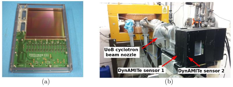
The detectors used for this study were DynAMITe CMOS APS devices developed by the MI-3 Plus consortium (RC-UK EP/G037671/1 programme) for biomedical applications (Esposito et al 2011). This is a wafer-scale radiation-hard sensor of total active area 12.8 cm × 12.8 cm. A picture of a sensor is shown in Figure 1a. The sensitive region is a 12 μm epitaxial, with a substrate layer of approximately 700 μm (Esposito et al 2012) mounted onto an aluminium backing. For transport and use, each DynAMITe sensor is housed in an aluminium casing with a removable carbon-fibre entrance window.
Figure 1.
(a) The DynAMITe sensor and (b) The Double DynAMITe set-up.
DynAMITe is essentially two imagers in one: a pixel (P) camera (high dynamic range; 1260×1280 pixels; 100 μm pitch) and a sub-pixel (SP) camera (low noise; 2520×2560 pixels; 50 μm pitch) both with a digitization of 14-bit signal depth. Sensor read-out occurs using a rolling-shutter in which rows are read-out in sequence to build up a frame. Region-of-interest (ROI) read-out is possible with an increased frame-rate. For example, although a full-frame read-out can be performed with a maximum frame-rate of 6.5 Hz (SP-mode), 10 rows may be read out at approximately 1400 Hz.
For part of this work two DynAMITe devices were stacked to provide a two-layer telescope in a “Double DynAMITe” configuration. The two devices were connected with a SMB trigger cable and read-out was synchronized using a master clock. Corresponding rows in the ROIs of two sensors were read-out simultaneously to provide synchronized image frames. A picture of the Double DynAMITe arrangement at the UoB Cyclotron is shown in Figure 1b. The imaging planes of the upstream and downstream sensors were physically separated by approximately 50 mm, with 0.7 mm of silicon (substrate) and 2 mm of aluminium (sensor backing) as intermediate material.
2.3. Experiments
The SP-camera mode of DynAMITe was used in this work as the low-noise characteristics provide the greater potential for resolving individual proton events. In all cases dark images were obtained immediately before a series of measurements and subtracted from the subsequent acquisitions to reduce fixed-pattern noise. Some preliminary full-frame images were acquired for testing, but the bulk of the work presented here was for low beam currents and high-frame rates using ROI read-out. The experiments with the DynAMITe sensor can be divided in to three main phases: (1) a demonstration of proton-counting at UoB using a 36 MeV beam; (2) a demonstration of proton-counting at iThemba with therapy beams and; (3) an investigation of proton tracking at UoB using Double DynAMITe.
The first experimental phase used a 10-row ROI with a frame integration time of t = 0.717 ms. The nominal beam currents used ranged from IUoB = 5×10⁻⁴ to 0.5 nA. The proton energy was approximately 36 MeV at exit from the UoB Cyclotron nozzle and a 50 mm diameter beam was used. The second experimental phase, at iThemba, again used a 10-row ROI read-out (t = 0.717 ms) with a nominal beam current of IiTh = 0.1 to 1 nA and a 100 mm diameter beam. Proton beam ranges were selected from 30 to 240 mm in the second phase. In the UoB and iThemba experiments 100-500 frames were collected in each acquisition.
The final experimental phase used the Double DynAMITe configuration and the UoB beam (IUoB ≈ 5×10⁻⁴ nA). A 200-row ROI (t = 12 ms) was selected to encompass the potential extent of lateral scattering of the protons between sensors. A 2.3 mm diameter pinhole collimator was used to collimate the beam prior to the upstream sensor. The narrow collimation clustered the majority of protons towards the central rows of the image in the first sensor. Due to the nature of the rolling shutter read-out, there was a finite chance of a particular proton in a frame appearing in the previous or following frame in the downstream sensor. To reduce the incidences of this, 498 acquired frames were re-grouped into sets of three consecutive frames and the events in each set added to produce 166 frame-averaged images.
2.4. Clustering algorithm
In order to quantitatively analyse the results of the proton counting experiments, it was necessary to develop an algorithm that would identify clusters of pixels that constituted an event and tag them as such. An automatic clustering algorithm was developed with the following stages: (1) Subtraction. Residual pattern noise along the rows was removed by applying a 10-pixel median filter along this direction and subtracting this from the original image; (2) Binary segmentation. If the Digital Number (DN) of pixel-value was ≥30 it was considered part of an event and segmented as such; (3) Expansion. A 5-pixel 2D maximum filter was applied to the binary image; (4) Definition. Contiguous pixels, designated as event pixels, were assigned to the same event.
The threshold of 30 DN is equivalent to a collection charge of ≈ 1500 e−, and, assuming 3.6 eV per e-h pair, an energy deposition of 5.4 keV in a pixel. This threshold empirically proved a satisfactory compromise between being large enough to exclude the temporal noise (σ not larger than 6 DN) and small enough to exclude only a small fraction of genuine events. A lower threshold than 30 DN could be used however more sophisticated techniques for rejecting false-positives may be necessary and are under investigation. The final result of the clustering algorithm was a set of masks covering the identified events.
2.5. Simulations
Monte Carlo simulations were conducted to support the analysis of the proton-counting experiments. The objective was to determine if the frequency and characteristics of observed candidate events was consistent with that expected for protons of the corresponding energies. Simple simulations were conducted using the FLUKA Monte Carlo program (Ferrari et al 2005) and the FLAIR interface (Vlachoudis 2009). No detailed beam-modelling of the UoB and iThemba nozzle geometries was conducted.
The UoB beam was modelled as a 50 mm diameter parallel beam with a mono-energetic proton energy close to the nominal 36 MeV. The precise energy was adjusted to match the experimental results.
The 240 mm range iThemba beam was modelled by assuming a 100 mm diameter parallel beam with the proton energy following a Gaussian distribution. A depth-dose curve in water was simulated and the initial mean beam energy (Eb) and momentum FWHM (σp) were adjusted to produce a range in water of 240 mm and a FWHM of 25 mm. The values obtained were: Eb = 190.5 MeV and σp = 3.5 MeV/c. A degraded beam was created by inserting a thickness of graphite into the simulation. This thickness was adjusted to match the experiment.
In all cases a simulation consisted of 105 primary protons. The detector was modelled as a 712 μm of silicon, with the energy deposited in the first 12 μm being scored event by event using the EVENTBIN scoring card. The energy of the protons passing through this region was modulated by the insertion of varying thicknesses of Polymethyl methacrylate (PMMA), to produce a Bragg curve.
The predicted signal (S in DN) in the CMOS was calculated using the simulated energy deposited (ΔE in eV), the known gain of the DynAMITe sensor (G = 50 e−/DN) (Esposito et al 2011) and the electron-hole pair creation energy of silicon (Ee−h = 3.6 eV/pair) (Johnson et al 2003). Thus:
| (1) |
3. Results
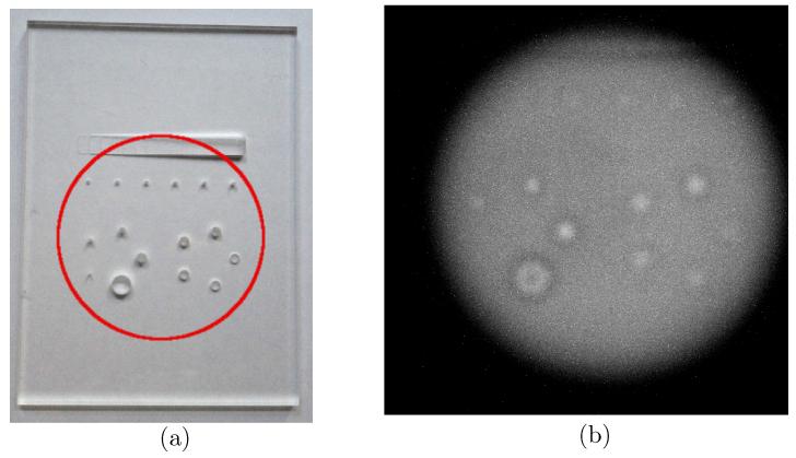
As a preface to the demonstration of the capability of CMOS APS detectors for use in proton-counting applications, a motivation for such a use will be illustrated with an experimental image. Figure 2a shows a contrast-detail phantom manufactured from an 8 mm thick sheet of PMMA, with a number of holes of varying size and depth. A section of the phantom (illustrated with a red circle in Figure 2a) was imaged using the DynAMITe sensor. Figure 2b shows a full-frame image acquired with the 100 mm diameter iThemba beam (30 mm range beam; IiTh = 50 nA; t = 153.3 ms). Within the beam, many protons contribute signal to each pixel. Although many of the features of the phantom can be identified from this proton radiograph, the image is not a completely faithful representation of the object. For example, protons that have passed through a hole in the phantom will retain a higher energy and so deposit less energy in the detector. However, there will also be scatter into this region from protons that have passed through the phantom material in the surrounding regions. The net signal in a detector plane depends on the interplay of energy-loss and influence and is therefore dependent on the initial proton energy, the geometry and the object imaged. The observed blurring and halo effects are the result. In a proton-counting telescope, however, the effects of scatter and proton energy-loss on signal can potentially be distinguished, promising an improved image.
Figure 2.
(a) A PMMA contrast-detail phantom and (b) a proton radiograph of the phantom using the DynAMITe sensor and an iThemba beam (30 mm range, IiTh = 50 nA).
With a low-enough beam current and a fast ROI read-out only a few protons should be present in any image frame. Figure 3a shows a 300×10 pixel section of an ROI frame (no phantom present) acquired with DynAMITe at the UoB Cyclotron (IUoB = 0.05 nA; t = 0.717 ms). A few clusters of bright pixels can be observed for the 36 MeV protons. Figure 3b shows the result of running the frame through the clustering algorithm, yielding 5 event masks.
Figure 3.

UoB Cyclotron. (a) ROI image and (b) the corresponding event masks from the clustering algorithm.
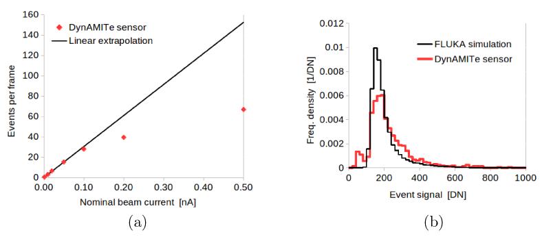
If such above-identified events are due to individual protons being resolved, the increase in event number should be initially linear with beam current, until at higher currents substantial pile-up begins to occur. This can be observed in Figure 4a, where a linear region occurs up to IUoB ≈ 0.1 nA. This is equivalent to ≈ 100 protons cm−2 in each frame within the beam-area. The degree of pile-up in general will depend on the pixel size and to some extent on the clustering algorithm. Figure 4a shows a histogram of integrated signal per event for an experimental acquisition (IUoB =0.05 nA) and the prediction of a FLUKA simulation. The form of both histograms resembles a spread-out Landau energy-loss curve (Leroy and Rancoita 2004) as expected for the energy-loss of charge particles in thin absorbers. The spread of the experimental signal is, however, larger than in the simulation. This is not unexpected, as charge collection and noise in the sensor is not modelled in the simple simulation. The cause of the minor secondary peak in the experimental histogram at low signal was not identified. However, the mean event signal (230 DN) was close to that simulated (200 DN) strongly supporting the idea that the events are indeed individual protons.
Figure 4.
UoB Cyclotron. (a) Events per frame versus beam current and (b) histograms of experimental and simulated event signal.
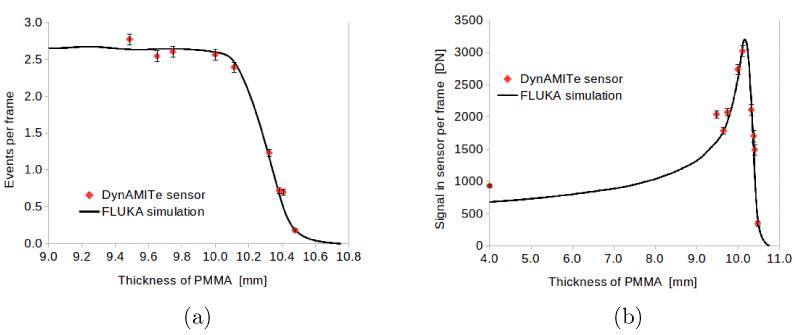
The addition of increasing thicknesses of PMMA was observed to decrease the event-rate in the sensor. Figure 5a illustrates this for IUoB = 0.5 pA. The simulation curve is the fall-off influence calculated using FLUKA for 35.55 MeV protons, normalised to agree with experiment for 9.5 mm of PMMA degrader. The agreement over the whole range of data is excellent. Figure 5b shows the experimental and simulated signal per frame (the product of events per frame and mean event signal). The experimental signal-depth curve resembles that of a Bragg peak as expected.
Figure 5.
UoB Cyclotron. (a) Event per frame versus thickness of PMMA degrader and (b) signal in frame versus thickness of PMMA.
The iThemba radiotherapy facility has a wide selection of proton energies available, with proton range extending up to 240 mm. For the undegraded protons in this maximum range beam, the protons passing through the sensor will possess an energy lying on the energy plateau far away from the Bragg peak. Figure 6a shows a 300×10 pixel region of a DynAMITe image for an ROI acquisition with this beam at iThemba (IiTh = 0.1 nA; t=0.717 ms) and Figure 6b shows the events detected by the clustering algorithm. Protons are still detectable, although, inevitably, there will be an increased probability of missing an event due to it falling below the noise threshold; an analysis of this is beyond the scope of the current work.
Figure 6.

iThemba. (a) ROI image and (b) the corresponding event masks from the clustering algorithm.
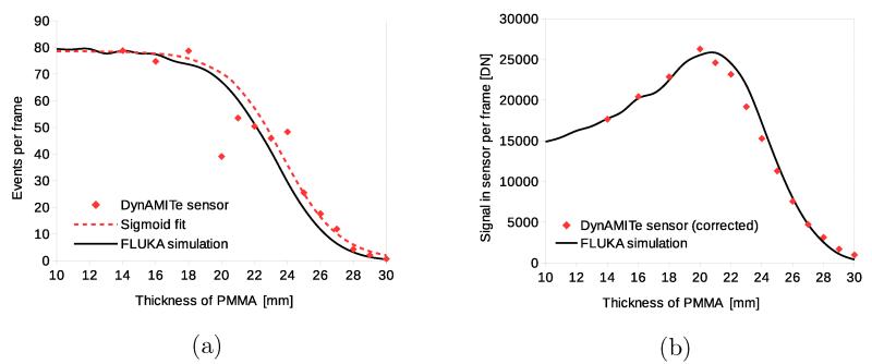
Figure 7a illustrates the fall-off of event-rate at iThemba with thickness of PMMA degrader for a 30 mm range beam. The general form of the simulated range curve is followed by the data. The 30 mm range beam was modelled as the 240 mm range beam degraded by 139 mm of graphite. There are marked and erratic departures from the simulated curve. However, this is likely to be due to the temporal beam instability at iThemba for the low nominal current used (IiTh = 1 nA). A sigmoid fit to the observed events per bin is also shown: ψ(x) = 78.6(1 + exp[−0.58(x − 23.7)])−1. Figure 7b shows the corresponding Bragg curve with good overall agreement to the simple Monte Carlo model. The experimental DN per frame plotted was corrected for fluence fluctuations: it was calculated as the product of the sigmoid t and the experimental mean DN per event. Note that Figure 7a and Figure 7b are much broader than the equivalent curves for the UoB Cyclotron (Figure 5a and Figure 5b) due to the initial energy spread of the cyclotron beam at iThemba and the subsequent straggling in degrading the beam to a 30 mm range.
Figure 7.
iThemba. (a) Event per frame versus thickness of PMMA degrader and (b) signal in frame versus thickness of PMMA.
A range telescope requires a stack of sensors and the ability to track individual protons through the system. The purpose of the Double DynAMITe experiment at the UoB was to demonstrate the feasibility of this. Figure 8a (upstream sensor) and 8b (downstream sensor) show a 400×200 pixel region centred on the pinhole collimator, with the event masks detected from all 166 re-grouped frames superimposed in each image. The events are clustered relatively close to the centre of the image in the upstream sensor due to the use of a pinhole collimator. In the downstream sensor, however, the distribution of events is much broader due to the scattering between imaging planes. Based on the beam-current and area and the size of the collimator hole, the expected number of events was between 2 and 3 protons per re-grouped frame. The observed numbers were consistent with this, with the counts in the second sensor being 78% of that in the first (2.1 versus 2.8 per frame). The event loss between upstream and downstream sensors is likely to be primarily due to lateral scattering out of the ROI. Figure 9a and 9b show an example corresponding upstream and downstream frame, respectively. Two event masks were identified by the clustering algorithm in each. This is suggestive of the ability to tracks individual protons through a stack of CMOS sensors.
Figure 8.
UoB Cyclotron. Cumulated events in all 166 frames in (a) the upstream and (b) the downstream sensor.
Figure 9.
Image frames for the (a) upstream and (b) downstream sensors.
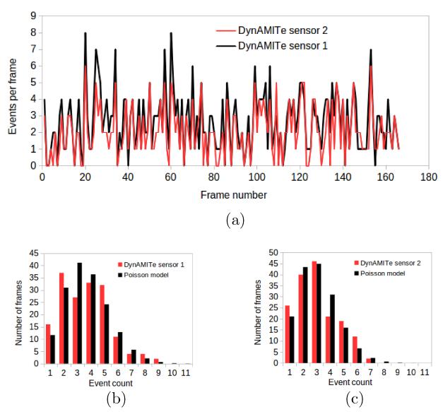
However, a single incidence of a correspondence in event number in two planes does not demonstrate tracking. A significant correlation in event number over a sequence of frames is necessary to rule out chance coincidence. Figure 10a shows the events per frame for the upstream and downstream sensors for the 166 re-grouped frames. Visually a correlation is apparent between sensors. This was confirmed by a high correlation coefficient: r = 0.854. A correlation less than unity is in line with expectations due to the stochastic nature of event loss between sensors. To rule out the possibility of a high correlation due to beam current fluctuations, a χ2 analysis was performed to test whether there was evidence of a departure from a simple Poisson distribution. If the mean current in the beam fluctuated substantially in the course of the acquisition, the variance in event number would be significantly greater than the average event number (σ2 > N) i.e. non-Poissonian. No evidence for a departure from simple Poisson was detected at the 5% level. The frequency distribution for the upstream and downstream plots, and the corresponding Poisson models, are shown in 10b and 10c, respectively. This suggests that when the number of events in the upstream detector is high, the number of events in the downstream detector also tends to be high because the same protons are being observed.
Figure 10.
(a) Events per frame versus frame number for both sensors, and (b) and (c) the event number frequency distribution versus Poisson models, for upstream and downstream sensors, respectively.
4. Discussion
The ability of the DynAMITe sensor to resolve individual proton events has been unambiguously demonstrated. From the combined evidence presented in Figure 4 and Figure 5 it is clear that the properties and frequencies of events match closely with the expectations from simulations. Figure 6 and Figure 7 demonstrate that this event-counting is also possible with real treatment beams over a wide range of proton energies. Figure 8 to Figure 10 further demonstrate the principle of proton tracking and a range telescope. Note that the further any two protons are spatially separated in a sequence of layers the greater confidence than can be obtained in associating particular events in the layers to the particular protons. This requires further study in the context of a pixelated multi-layer telescope.
There are many challenges that need addressing in order to make a practical CMOS APS telescope. A large-area (≈10×10 cm2) sensor would need to be built with a fast full-frame read-out at a rate comparable to the ROI read-out rate obtained in this work. The ROI frame-rate using the DynAMITe sensor was between 83 Hz (200 rows) and 1400 Hz (10 rows). In order to provide a reasonable imaging time with full field-of-view imaging, a design specification of 1000 Hz has been set for full-frame readout for future sensors designed for proton-radiography within the PRaVDA Consortium. While satisfying this requirement, several bits of signal read-out are also necessary to obtain useful information on the energy of the proton. Pixel-size is also a consideration. The larger the choice of pixel size (for a fixed size sensor), the fewer the number of pixels, and hence the easier it is to provide a given read-rate for a fixed bit-depth. Yet, at high-enough beam current, event pile-up will become a problem (see Figure 4a). For a larger pixel size, event pile-up will occur at a lower proton current. There is also sizeable stochastic variation in signal from event to event (see Figure 4b). It is currently unclear to what degree this will obscure proton energy discrimination using the pixel signal. This stochastic variation might be reduced, however, for example, by increasing the epitaxial layer thickness (and hence the sensitive volume). The effects of detector design on sensor radiation hardness are currently under investigation.
Additional considerations are necessary for the construction of a telescope itself which include: the number of layers, material thickness between layers and physical layer separation. The first and second factors determine the range of proton energies that can be stopped in the telescope. The second and third the degree of lateral scattering between layers (and hence difficulty of track reconstruction). The rejection of secondary background events such as gamma emissions, energetic electrons and alpha particles is also worth further attention. In a single detector plane, rejection could potentially be based on event size (pixels) or event magnitude (signal). The very different (or lack of) track structure through multiple planes may be a further basis for event association and rejection.
These are amongst the challenges the PRaVDA Consortium are considering in designing future CMOS APS devices for proton radiography applications.
5. Conclusion
The capability of CMOS APS technology for proton-counting and tracking applications for therapy systems has been demonstrated. The ability to resolve the passage of individual therapy protons in a large-area CMOS APS detector, due to their ionisation/excitation events, has been clearly established. The proof-of-principle of the tracking of protons through multiple layers of such sensors has also been shown for the first time.
With the advances in mainstream CMOS device design and fabrication, namely, large-area, high-speed and radiation-hardness, it is realistic to consider CMOS APS technology for the realisation of the necessary instrumentation to monitor and augment proton therapy systems. The potential utility of such devices is in treatment setup and concurrent validation, as well as providing either proton imaging as a stand-alone modality or in fusion with more conventional x-ray CT images. The fundamental advantages of proton therapy, namely very high doses in small volumes, demand the use of such instrumentation.
Acknowledgments
The authors wish to thank aSpect Systems GmbH and ISDI Limited for their support and development of the PRaVDA system. The authors further acknowledge the support and insight of the whole PRaVDA team. Our thanks also extend to Julyan Symons (iThemba LABS, Cape Town, SA) for his generous assistance. This work was supported by the Wellcome Trust Translation Award Scheme, Grant Number 098285.
Footnotes
PACS numbers: 8755-x, 8759bf, 8757nf
References
- [1].Wilson RR. Radiological use of fast protons. Radiology. 1946;47:487–491. doi: 10.1148/47.5.487. [DOI] [PubMed] [Google Scholar]
- [2].Goethals P-E, Zimmermann R. Proton Therapy World Market Report Edition 2013. MEDraysintell; Grez-Doiceau (BE): Lalaye (FR): 2013. [Google Scholar]
- [3].Paganetti H. Range uncertainties in proton therapy and the role of Monte Carlo simulations. Phys Med Biol. 2012;57(11):R99–117. doi: 10.1088/0031-9155/57/11/R99. [DOI] [PMC free article] [PubMed] [Google Scholar]
- [4].Evans PM. Anatomical imaging for radiotherapy. Phys Med Biol. 2008;53(12):R151–R191. doi: 10.1088/0031-9155/53/12/R01. [DOI] [PubMed] [Google Scholar]
- [5].Yohannes I, Kolditz D, Langner O, Kalender WA. A formulation of tissue- and water-equivalent materials using the stoichiometric analysis method for CT-number calibration in radiotherapy treatment planning. Phys Med Biol. 2012;57(5):1173–90. doi: 10.1088/0031-9155/57/5/1173. [DOI] [PubMed] [Google Scholar]
- [6].Yang M, Zhu XR, Park PC, Titt U, Mohan R, Virshup G, Clayton JE, Dong L. Comprehensive analysis of proton range uncertainties related to patient stopping-power-ratio estimation using the stoichiometric calibration. Phys Med Biol. 2012;57(13):4095–115. doi: 10.1088/0031-9155/57/13/4095. [DOI] [PMC free article] [PubMed] [Google Scholar]
- [7].Cormack AM. Representation of a Function by its Line Integrals, with Some Radiological Applications. J. Appl. Phys. 1963;34:2722. [Google Scholar]
- [8].Steward VW, Koehler AM. Proton Beam Radiography in Tumor Detection. Science. 1973;179(4076):913–914. doi: 10.1126/science.179.4076.913. [DOI] [PubMed] [Google Scholar]
- [9].Hanson KM. Proton computed tomography. IEEE Transactions on Nuclear Science. 1979;NS-26(1):1635–1640. [Google Scholar]
- [10].Schneider U, Besserer J, Pemler P, Dellert M, Moosburger M, Pedroni E, Kaser-Hotz B. First proton radiography of an animal patient. Med Phys. 2004;31(5):1046–51. doi: 10.1118/1.1690713. [DOI] [PubMed] [Google Scholar]
- [11].Sadrozinski HF-W, Johnson RP, Macafee S, Plumb A, Steinberg D, Zatserklyaniy A, Bashkirov VA, Hurley RF, Schulte RW. Development of a head scanner for proton CT. Nuclear Instruments and Methods in Physics Research. 2013;A699:205–210. doi: 10.1016/j.nima.2012.04.029. [DOI] [PMC free article] [PubMed] [Google Scholar]
- [12].Civinini C, et al. Towards a proton imaging system. Nuclear Instruments and Methods in Physics Research. 2010;A623:588–590. [Google Scholar]
- [13].Amaldi U, Bianchi A, Chang Y-H, Gob A, Hajdas W, Malakhov N, Samarati J, Sauli F, Watts D. Construction, test and operation of a proton range radiography system. Nuclear Instruments and Methods in Physics Research. 2011;A629:337–344. [Google Scholar]
- [14].Rinaldi I, Brons S, Gordon J, Panse R, Voss B, Jakel O, Parodi K. Experimental characterization of a prototype detector system for carbon ion radiography and tomography. Phys Med Biol. 2013;58(3):413–27. doi: 10.1088/0031-9155/58/3/413. [DOI] [PubMed] [Google Scholar]
- [15].Schneider U, Besserer J, Hartmann M. Technical note: spatial resolution of proton tomography: impact of air gap between patient and detector. Med Phys. 2012;39(2):798–800. doi: 10.1118/1.3676739. [DOI] [PubMed] [Google Scholar]
- [16].Esposito M, Anaxagoras T, Fant A, Wells K, Konstantinidis A, Osmond JPF, Evans PM, Speller RD, Allinson NM. DynAMITe: a wafer scale sensor for biomedical applications. JINST. 2011;6:C12064. [Google Scholar]
- [17].Sanchez-Crespo A, et al. Proton therapy beam dosimetry with silicon CMOS image sensors. Nucl. Instrum. Methods Phys. Res. A. 2004;525:289–293. [Google Scholar]
- [18].Seco J, Depauw N. Proof of principle study of the use of a CMOS active pixel sensor for proton radiography. Med Phys. 2011;38(2):622–3. doi: 10.1118/1.3496327. [DOI] [PubMed] [Google Scholar]
- [19].Esposito M, Anaxagoras T, Diaz O, Wells K, Allinson NM. Radiation Hardness of a Large Area CMOS Active Pixel Sensor for Bio-medical applications. IEEE Nuclear Science Symposium and Medical Imaging Conference Record (NSS/MIC) 2012;N14-183:1300–1304. [Google Scholar]
- [20].Ferrari A, Sala PR, Fasso A, Ranft J. FLUKA: a multi-particle transport code. CERN; 2005. (INFN/TC05/11, SLAC-R-773). [Google Scholar]
- [21].Vlachoudis V. FLAIR: a powerful user friendly graphical interface for FLUKA; International Conference on Mathematics, Computational Methods & Reactor Physics; Saratoga Springs, New York. Illinois, USA: American Nuclear Society; 2009. [Google Scholar]
- [22].Johnson L, Keeney B, Ross G, Sadrozinski HF-W, Seiden A, Williams DC, Zhang L, Bashkirov V, Schulte RW, Shahnazi K. Initial studies on proton computed tomography using a silicon strip detector telescope. Nucl. Inst. Meth. 2003;A514:215–223. [Google Scholar]
- [23].Leroy C, Rancoita PG. Principles of Radiation Interaction in Matter and Detection. World Scientific Publishing Co.; Singapore: 2004. [Google Scholar]


