Abstract
There is a continuing need to increase the brightness and photostability of fluorophores for use in biotechnology, medical diagnostics and cell imaging. One approach developed during the past decade is to use metallic surfaces and nanostructures. It is now known that excited state fluorophores display interactions with surface plasmons, which can increase the radiative decay rates, modify the spatial distribution of emission and result in directional emission. One important example is Surface Plasmon-Coupled Emission (SPCE). In this phenomenon the fluorophores at close distances from a thin metal film, typically silver, display emission over a small range of angles into the substrate. A disadvantage of SPCE is that the emission occur at large angles relative to the surface normal, and at angles which are larger than the critical angle for the glass substrate. The large angles make it difficult to collect all the coupled emission and have prevented use of SPCE with high-throughput and/or array applications.
In the present report we describe a simple multi-layer metal-dielectric structure which allows excitation with light that is perpendicular (normal) to the plane and provides emission within a narrow angular distribution that is normal to the plane. This structure consist of a thin silver film on top of a multi-layer dielectric Bragg grating, with no nanoscale features except for the metal or dielectric layer thicknesses. Our structure is designed to support optical Tamm states, which are trapped electromagnetic modes between the metal film and the underlying Bragg grating. We used simulations with the transfer matrix method to understand the optical properties of Tamm states and localization of the modes or electric fields in the structure. Tamm states can exist with zero in-plane wavevector components and can be created without the use of a coupling prism. We show that fluorophores on top of the metal film can interact with the Tamm state under the metal film and display Tamm state-coupled emission (TSCE). In contrast to SPCE, the Tamm states can display either S- or P-polarization. The TSCE angle is highly sensitive to wavelength which suggests the use of Tamm structures to provide both directional emission and wavelength dispersion. Metallic structures can modify fluorophore decay rates but also have high losses. Photonic crystals have low losses, but may lack the enhanced light-induced fields near metals. The combination of plasmonic and photonic structures offers the opportunity for radiative decay engineering to design new formats for clinical testing and other fluorescence-based applications.
Keywords: Radiative Decay Engineering, One-Dimensional Photonic Crystals, Tamm States, Tamm State-Coupled Emission, Surface Plasmon-Coupled Emission, Metal-Enhanced Fluorescence
INTRODUCTION
Fluorescence detection is one of the most widely used tools in the biosciences, with applications to cell imaging, medical diagnostics, biophysics, DNA sequencing and protein arrays. Beginning with the initial applications of fluorescence to biochemistry in the 1960s, there have been continual improvements in probe chemistry, light sources, optics and detectors. At present, probes have high quantum yields and detectors have reached maximum quantum efficiencies. As a result of these advances there are only limited opportunities to increase the observed brightness of fluorophores using classical far-field free-space optics. Because of these limitations we began an investigation of the effects of metallic particles and surfaces on fluorescence. We took this approach because there was an opportunity to increase the brightness of fluorophores by coupling both excitation and emission to surface plasmons [1-3], which can result in metal-enhanced fluorescence (MEF) [4-5]. Additionally, we saw the opportunity to convert the usual omni-directional fluorescence to directional emission by using wavevector matching at the metal surfaces [6-7]. This phenomenon is called Surface Plasmon-Coupled Emission (SPCE). We refer to these general approaches as Radiative Decay Engineering (RDE) to emphasize the distinction from classical fluorescence with unrestricted free-space emission. The interaction of fluorophores with metals is now an active area of research.
Many laboratories have reported that metallic particles of Ag, Au and Al can enhance the emission intensities in both ensemble and single molecule experiments [8-14] at wavelengths from the UV to the NIR [15-17]. Novel plasmon-coupled probes have been reported, which are composite structures of fluorophores with metal particles or fluorophores contained in nanoshells. These probes display single particle intensities which are comparable to quantum dots [18-24]. One of the most remarkable aspects of RDE is its ability to design the desired directional and wavelength distribution of the emission using nanostructured metal surfaces [25-27]. All these effects are based on the same phenomenon, which is the interaction of fluorophores (dipoles) with resonant or non-resonant plasmons on the metal nanoparticles or surfaces [28-31]. These interactions can occur during both excitation, via the high light-induced fields, or during emission by changes in the radiative decay rate [32-35]. Fluorophore-plasmon coupling offers the opportunity to combine fluorescence with the rapidly developing field of plasmonics [36-39].
Photonic crystals (PCs) offer another approach for modification of fluorescence. Photonic crystals are comprised of dielectrics rather than metals. PCs typically contain repeated structural features, which are comparable in size to 0.25 to 1.0 wavelengths. PCs can have features in 1, 2 or 3 dimensions [40-41]. In the present report we will deal only with 1 dimensions (1D) PCs, which consist of alternative layers of high (H) and low (L) dielectrics of appropriate thickness. These structures are sometimes referred to as Bragg gratings (BGs). PCs and BGs display the remarkable phenomenon of photonic band gaps (PBGs). A PBG is a range of wavelengths of light which cannot propagate in the structure. These wavelengths are almost completely reflected. Reflection by a PC with a PBG is different from reflection by a metal. In the case of metals the electrons in the metal oscillate in response to the incident light so that the electric field direction is reversed. In a PC with a PBG the incident light penetrates a short distance into the PC as an attenuated wave, which is then reflected out of the PC. Reflection at a PBG analogous is to total internal reflection (TIR) at a dielectric-air interface. Since PBGs often exist over a narrow range of wavelengths, PCs often display bright colors that are determined by which wavelengths are accepted or repelled by the structure. These colors exist without chromophores and are sometimes called structural colors [42-43]. Typically the optical constants of dielectrics vary slowly with wavelength. As a result the optical properties usually scale with the physical dimensions of the structure. An important difference between PCs and metals is that the dielectrics in PCs have low losses at visible wavelengths. Hence the quality factors for a mode can be high and there are less quenching or energy losses than with metals.
The high scientific interest in PCs gives the impression of a long scientific history. However, PBGs were first predicted rather recently in 1987 [44-45]. Most experimental results on PCs are focused on the physics or their application to fiber optic communications where they are referred to as distributed BGs [46]. There have been a limited number of publications on the effects of PCs on fluorescence, mostly using 3D colloidal dielectric crystals [47-48]. Recently, we have reported on properties of fluorophores on 1DPCs [49-50]. We found that fluorophores located within the strong fields of Bloch surface waves (BSWs) or internal modes of the 1DPC efficiently emit into the radiation modes, yielding sharp angular distribution of emission in and through the substrate. We refer to this phenomenon as Bragg Grating-Coupled Emission (BGCE). However, BGCE and SPCE share the same disadvantage. In both cases the emission appears at large angles relative to the surface normal (Scheme 1). These angles are above the critical angle (outside the light cone) which in turn requires immersion objectives for efficient collection of the emission. Also, incident light from the air cannot interact with these resonances. A prism or grating coupler is needed to increase the wavevector of the incident light [50-52].
Scheme 1.
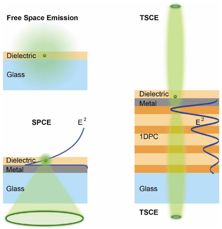
Comparison of a free space emission and Surface Plasmon-Coupled Emission (SPCE) with a Tamm State-Coupled Emission (TSCE).
In the present paper we extend our previous work on fluorescence using plasmonic or photonic structures to a structure which contains features of both plasmonic and photonic components. We chose this approach because it offers the opportunity to allow both excitation and emission to occur within the light zone, at angles less than the critical angle. In fact, depending on dimensions and wavelengths the emission can be directed either away from or back through the structure at directions perpendicular to the surface (Scheme 1). The excitation light can be incident on the sample from either direction, and perpendicular to the surface. In contrast to Surface Plasmon Resonances (SPR) or SPCE neither a prism nor a grating coupler are needed. These unusual possibilities are the result of the relatively unknown phenomenon of optical Tamm states. Tamm states are named after Igor Tamm who described their existence at the atomic scale and linked to the periodicity of the atoms in a crystal [53]. Tamm states are relatively unknown and are not mentioned in well-known books on photonics [40-41], and are not mentioned in the classic texts by Born and Wolf [54] or Ashcroft and Mermin [55]. It was not until 2005 that similar optical states were shown to exist between two BGs [56] and between a metal film and a BG [57-58]. The state between two dielectric BGs are usually called optical Tamm states (OTS) [59-60]. The states between a BG and a metal film are often called Tamm plasmons or Tamm plasmon polaritons [61-62] to indicate the involvement of electron oscillations. An advantage of plasmonic Tamm states over OTS is that the OTS require a prism coupler [63]. A prism is not needed for the structure described in this report. As will be shown below, the electric fields for the Tamm states are usually localized below the metal film, just below the metal-dielectric interface. For this reason we will refer to the states simply as Tamm states to avoid specifying the role of the plasmons in the Tamm fields.
Tamm states have unusual properties which can be advantageous for use in sensors, and the next generation of fluorescence multiplex arrays and device formats. The creation of surface plasmons on a metal film requires the light to be incident on the sample at the surface plasmon resonance angle (θSPR). The light must also be incident though a prism and be P-polarized (Scheme 1). S-polarized light does not create plasmons, nor does light incident at any angle from the air side of the sample. The surface plasmons are localized at the metal-air (sample) interface with evanescent fields in both the metal and air (sample) regions. In contrast, Tamm plasmons can be created by perpendicular incident light, or at other angles with either S- or P-polarized incident light. Surface plasmons must have an in-plane (x-axis) component of the wavevector. A Tamm plasmon can be S- or P-polarized and the in-plane wavevector can be zero. This absence of in-plane propagation offers the opportunities for “slow light” which can increase the interactions with fluorophores [64-65]. Tamm plasmons do have a disadvantage, which is that the modes are under the metal film (Scheme 1). Because of this field location, one might predict that the Tamm plasmons would be unable to interact with fluorophores above the metal. In this report we show that fluorophores above the metal surface can couple with the Tamm plasmons to yield Tamm Plasmon-Coupled Emission perpendicular to the sample plane. We believe the combination of plasmonic and photonic components in a single structure offers new opportunities for novel device formats for applications of fluorescence to the biosciences.
MATERIALS AND METHODS
Materials
Silver (purity 99.999%), poly(vinylalcohol) PVA, MW 13000-23000, sulforhodamine 101 (S101), rhodamine B (RhB) rhodamine 6G (Rh6G) and fluorescein (FL) were purchased from Sigma-Aldrich. Glass microscope slides were obtained from VWR. Nanopure deionized water was used for all solution preparations.
Simulations
Transmission and reflectance spectra were simulated using a commercial package TFCalc and by code written independently by one of the authors (E.D.). The calculations are based on the Transfer Matrix Method [40]. Both software packages gave identical results. The optical constants for silver were taken from reference [66].
Preparation of Substrate
Our Tamm structure does not contain any nanoscale size surface features and thus can be fabricated using well-known thin-film methods [67-69]. The Tamm substrate was fabricated using plasma-enhanced chemical vapor deposition (PECVD) of SiO2 and Si3N4 on standard microscope slides. Prior to PECVD of the Tamm substrates the glass slides were cleaned with piranha solution then with nanopure deionized water and dried with air stream. SiO2 is the low (L) refractive index dielectric and Si3N4 is the high (H) refractive index dielectric, with thicknesses of 55 and 105 nm, respectively. The sequence of layers was (HL)6 with an additional 55 nm thick layer of Si3N4 as the top dielectric (Figure 1). Tamm state structures typically use the high dielectric constant material for the top dielectric layers [70]. The dimensions were selected based on simulations of the reflectance spectra. The optical constants for SiO2 and Si3N4 were from reference [49]. This dielectric structure without the metal film is referred to as a Bragg grating (Figure 1). To form the Tamm state structure, the BG was coated with a 42 nm thick layer of silver by sputtering or vapor deposition. We used an Edwards Auto 306 Vacuum evaporation chamber under high vacuum (<5 × 10⁻⁷ Torr) for the deposition of the silver layer. The deposition rate (~1.0 nm/min) was adjusted by the filament current and the thickness of the deposited film was measured with a built-in quartz crystal microbalance. The Tamm structure was then coated with 45 nm of polyvinyl alcohol (PVA), which contained about 1 μM fluorophore. The solution was 1% PVA, (mw 16,000-23,000) in water, 3000 rpm for 1 minute, which yielded a thickness of 45 nm [49,71]. The actual thickness and optical constants were determined using a N and K Model 1200 ellipsometer and the obtained data is in agreement with those reported previously [49]. We did not use a dielectric spacer between the fluorophore in PVA and the metal surface.
Figure 1.
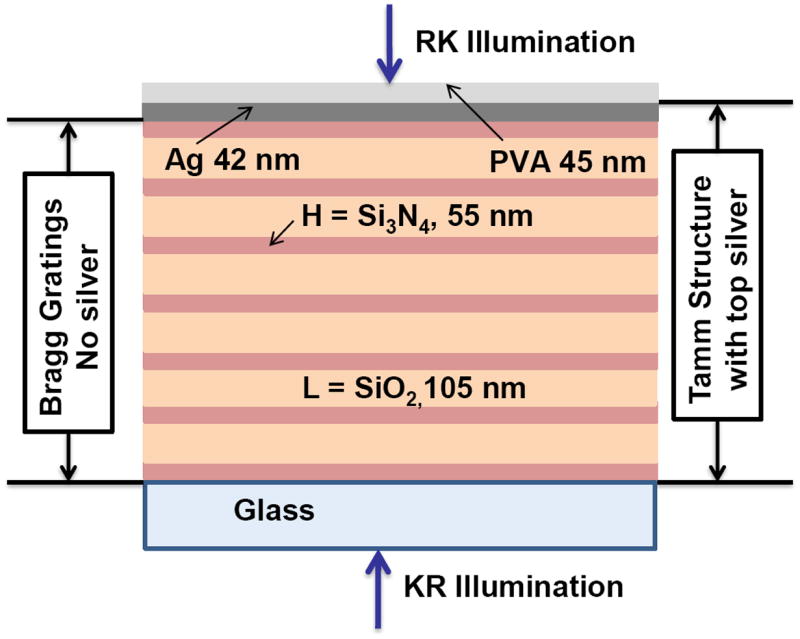
Schematic for the Tamm structure (TS) and Bragg grating (BG).
We selected four fluorophores for these experiments; sulforhodamine 101 (600 nm), rhodamine B (569 nm), rhodamine 6G (546 nm) and fluorescein (520 nm), where the numbers in parenthesis indicates their emission maxima. As will be seen from the simulations and experimental results the emission maxima of RhB, Rh6G and Fl are within wavelength range of the Tamm state of our structure. The emission maximum of S101 is outside the wavelength range for the structure to support Tamm states. Angle-dependent fluorescence intensities and emission spectra were collected using the apparatus described previously [6-7]. Excitation was obtained from either a CW 532 nm Nd-YVO4 laser or a 472 nm CW laser diode. The emission was collected using Model SD2000 Ocean Optics spectrometer with a 1 mm diameter optical fiber (NA 0.22) placed 2 cm from the sample. Polarizers were placed between the sample and fibers as needed. For 532 nm excitation a 550 nm long-pass emission filter was used to remove scattered light. A 500 nm long-pass filter is employed to reject the scatter from the 470 nm laser excitation. The intensity decays were collected using TCPSC instrument (PicoQuant, Fluotime 100) by employing the pulsed laser diodes from PicoQuant (100 ps, 400 MHz) as the light source.
Optical Geometry for Measurements
To avoid any ambiguities in the measurements we show the experimental geometry in Figure 2. The vertical direction in the laboratory is the out-of-plane axis. The Tamm structure is placed on a hemi-cylindrical prism. This prism is not strictly necessary with a Tamm state but we retained the prism to be consistent with our previous measurements and to avoid changes in angle of the incident light or the emission. Incident light through the prism is called the Kretschmann (KR) configuration. Light incident from the sample side is called Reverse Kretschmann (RK) illumination. We will use the same notation for emission. The emission measured through the prism is called KR emission and from the air side is called RK emission or free-space. The polarization is defined relative to the planar surfaces of the sample. The E-field for TE or S-polarized light is parallel to the surfaces. If the electric vector is in the plane of incidence the light is TM or P polarized. An angle of 0 degrees is perpendicular to the KR side of the sample. An angle of 180 degrees is perpendicular to the RK or air side of the sample.
Figure 2.
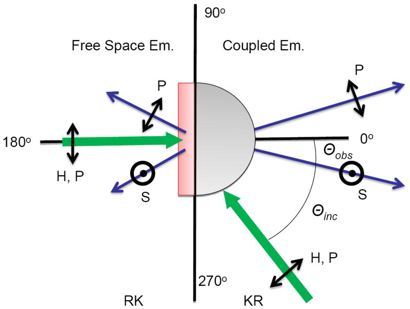
Experimental geometry and polarization used for the present measurements.
RESULTS
Full Dispersion Diagrams
In the physics literature the optical properties of plasmonic or photonic structures are described by dispersion diagrams [40-41,72-73]. Dispersion diagrams are typically two-dimensional plots, which show the mode dispersions in a photonic crystal as a function of photon energy and the wavevector component along the axis of interest. Figure 3 is a representation of the dispersion diagrams for our Tamm structure. These diagrams contain a great deal of information but they can be difficult to understand for someone not specialized in optics. Also, they can hide detailed features of the sample. Nevertheless, we feel they provide the best way to communicate the complexity of Tamm states and TSCE for different wavelengths, polarization incident, direction and angles of incidence. The physical meaning of these diagrams is best understood by comparison with the experimental results. Rather than giving a detailed description at this time we will refer back to Figure 3 as we discuss specific optical properties of our Tamm structure.
Figure 3.
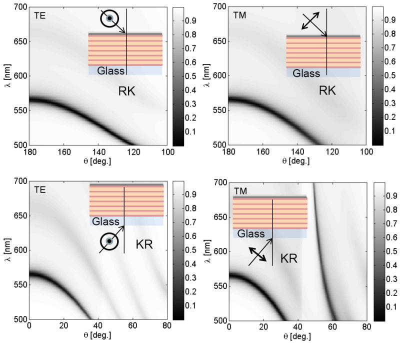
Calculated reflectivity dispersion diagrams for the Tamm structure shown in Figure 1. Insets show the illumination geometries and light polarizations.
Simulations
The unique properties of a Tamm state can be seen by comparison with the more familiar properties of surface plasmon resonances (Figure 4). An SPR structure consists of a thin metal film on a glass prism (Figure 4 Inset). A top layer of 45 nm thick PVA is added to be consistent with our experiments using the Tamm structure. The optical properties of the SPR structure are relatively easy to understand. In this case we show the angle-dependent reflectivity at a single wavelength. This is equivalent to a horizontal line across the lower right panel in Figure 4. Surface plasmons cannot be coupled by light incident from the air side (RK illumination). The reflectivity is high at all angles of incidence from the air side, for both TE(S) and TM(P) polarized light. Strong dips in the reflectivity can be seen with KR illumination through the prism, but only with TM or P-polarized light. This is because surface plasmons are TM(P) polarized. The dips in reflectivity occur at the surface plasmon angle (θSPR). Only one dispersion plot is needed for the SPR structure, which is for P-polarized KR illumination (lower panel). There is a single band of decreased reflectivity which shifts slightly with wavelength due to changes in the optical constants.
Figure 4.
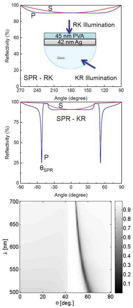
Angle-dependent reflectivity for a 42 nm thick silver film on a glass prism. The inset in the top panel shows the structure including the top 45 nm thick PVA coating. Top, 570 nm RK illumination and Middle, KR illumination. Bottom, wavelength and angle dependent reflectivity with P-polarized KR illumination.
The optical properties of a Tamm states are very different from the surface plasmons. Figure 5 (top panel) shows the angle-dependent reflectivities of our Tamm structure with 569 nm KR (left) or RK (right) illumination. We selected this wavelength because it matches the emission maximum of RhB. The simulations are for the emission maximum, and not the excitation wavelength, because we expect SPCE-like behavior [6-7] where the resonance drops in reflectivity coincide with the angular distribution of the coupled emission. In contrast to SPR (Figure 4), the Tamm structure displays dips in reflectivity with both KR and RK illumination (Figure 5). Additionally, the reflectivity is near zero at either 0 or 180 degree incidence, and the drop in reflectivity is seen for both P- and S-polarized emission. The Tamm structure also shows the usual SPR resonances at 54 degrees with P-polarized KR illumination (top left). These simulations suggest that Tamm state-coupled emission may occur perpendicular to the sample plane and may occur in either the KR or RK directions. In future experiments the emission could be restricted to the KR direction because it is known that Tamm states can exist even if the half-space above the BG is completely filled with metal [77-75]. Excitation and emission perpendicular to the surface is convenient for multi-well plates and protein or DNA array applications. The Tamm resonances at 0 and 180 degrees can be seen in the full dispersion diagram (Figure 3) where the decrease in reflectivity connects to the y (wavelength)-axes.
Figure 5.
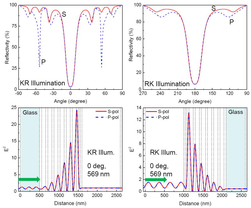
Calculated angle-dependent reflectivity (top) and the electric field intensity (bottom) for the Tamm structure shown in Figure 1 for 569 nm KR (left) and RK (right) illuminations.
Another unique feature of a Tamm state is the location of the optical modes or light-induced fields. For a SPR structure the field is located at the metal-sample interface on the side distal from the prism (Scheme 1). The presence of this evanescent field in the sample allows SPCE to occur. In contrast to a SPR field the Tamm field is located below the metal film and within the BG region of the sample (Figure 5, lower panels). The Tamm fields have similar intensities and are in the same location for KR or RK illumination. Tamm states are often described as surface trapped states [56-57], which gives the impression that they are localized precisely at the BG-metal interface. However, this is not the case. For our sample the Tamm fields are most intense in the top high dielectric layer, and more specifically closer to the next low dielectric layer. The Tamm fields occur throughout the Tamm structure which suggests a means for TSCE to occur at 0 degrees down through the sample. Very little of the Tamm field exists on the sample side above the metal, which suggests there will be weak coupling of fluorophores with the Tamm states. However, our previous work showed that fluorophores could display coupling with surface plasmons even when freely propagating light at the same wavelength could not interact with the structures [3]. We speculated that since the magnitude of the electric field on the fluorophore side of the metal is greater-than zero, excited state fluorophores could couple with optical Tamm sates, which in turn could result in TSCE.
The preceding simulations suggests that Tamm states could provide emission normal to the sample plane, which is useful for array based assays with physically separate locations for each analyte. Multiplex assays can also be accomplished using multiple wavelengths. We questioned if Tamm states could be used for wavelength separation. Figure 6 shows the S-polarized reflectivity of our structure for various wavelengths, which correspond to the emission maxima of the other probes used in this report. Similar results were found for P-polarized illumination except for the addition P-polarized surface plasmon resonances (Figure S1). A reflectivity drop at 0 or 180 deg incidence is only seen for 569 nm, which was our target wavelength for a Tamm structure that is suitable for RhB. At the two shorter wavelengths (546 nm for Rh6G and 520 nm for fluorescein) the resonances are found at off-axis angles for both KR and RK emission. Surprisingly, the reflectivity is not the same for KR and RK illumination, and the angular shift is larger for the RK than for the KR direction. A Tamm resonance is not seen at 600 nm (SR101), which is consistent with the absence of a Tamm state at 600 nm in the full dispersion diagrams (Figure 3). The wavelength dispersion of the Tamm structure (Figure 6) is larger than that found for the SPR structure (Figure 4). These simulations suggest Tamm structures can provide the function of several separate optical components. The Tamm structure can collect the emission, beam the emission towards a detector with wavelengths separated by angle, and suppress longer wavelength emission where a Tamm state does not exist.
Figure 6.
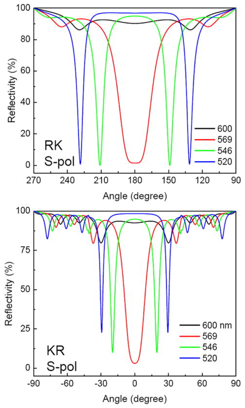
Calculated reflectivity for the Tamm structure for different incident wavelengths using RK (Top) and KR (Bottom) S-polarized illumination. The corresponding reflectivities for P-polarized illumination are shown in Figure S1.
The optical properties of the Tamm structure depend on angle, wavelength and polarization. It is difficult to measure all these parameters. In contrast it is simple to measure absorption or transmission. For comparison with the experimental results we show the calculated reflectivity spectra for the BG (Figure 7, top) and the Tamm structure (bottom) with RK illumination. Similar spectra were found for KR illumination and are shown in Figure S2. The BG structure (top) shows a photonic band gap (PBG) and high reflectivity at 520 nm. This peak shifts to shorter wavelengths at higher angles of incidence. A remarkable change is seen upon addition of the top silver layer (bottom). The wide PBG in the BG structure is replaced by a narrow resonance in the Tamm structure. These peaks also shift to shorter wavelengths at higher angles of incidence. This result shows that addition of the silver film increases light transmission by the sample within the PBG and specifically at the Tamm resonance wavelength. A similar effect has been reported on multi-layer metal-dielectric structures and has been described as plasmon-induced transparency [76-78]. These resonances can be visualized in Figure 3 by tracing a vertical line on dispersion diagrams.
Figure 7.
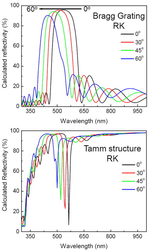
Calculated reflectivity of the Bragg grating without silver (Top) and the Tamm structure with silver (bottom) using RK illumination. Calculated reflectivities for KR illumination are shown in Figure S2.
Experimental Results
The BG and Tamm structures were fabricated as described in Materials and Methods. Figure 8 shows the apparent absorption spectra. We use the term apparent because our measurement does not separate absorption from reflection. Prior to addition of metal the BG structure (top) shows a PBG in good agreement with the simulated spectra shown in Figure 7. Addition of the metal layer resulted in increased transparency near 570 nm. The decrease in reflectivity corresponds to the Tamm resonance seen in Figure 7 (bottom). As predicted by the simulations this resonance shifts to shorter wavelengths at higher angles of incidence. We assign the dips from 500 to 570 nm to the Tamm state. These spectral shapes are similar to other reported Tamm state spectra [79]. Figure 9 shows color photographs of the Tamm structure (top panels) and a plane glass slide coated with 42 nm of silver (bottom panels). The silver-coated slide is almost completely opaque at any angle of incidence, which agrees with the high reflectivity seen in the top panel of Figure 4. When the same thickness of silver is placed on a BG, the Tamm structure becomes visibly transmissive (top panels). The transmitted light shifts from red to green with an increased observation angle, which is consistent with the shifts seen in Figure 8. Remarkably, combining two structures, a BG and a silver film, each with low transmission results in increased transmission at specific wavelengths.
Figure 8.
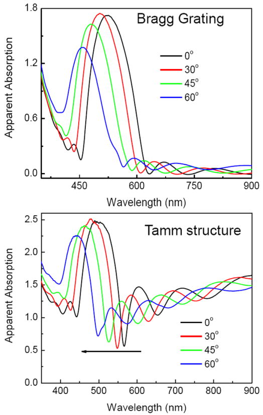
Apparent absorption of the Bragg grating (top) and the Tamm structure (bottom) with RK illumination. Similar spectra were found for KR illumination (not shown).
Figure 9.
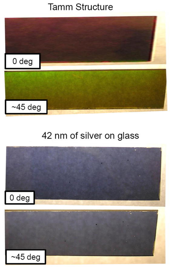
Color photographs of the Tamm structure (top) and 42 nm of silver on a plain glass slide (bottom) on a white light background. The degree refers to the observation angle from the normal.
Subsequently, we tested the Tamm structure for coupling of fluorophores with the underlying Tamm state. The Tamm structure was spin coated with 45 nm of PVA which contained RhB. Emission from the coated Tamm samples could be observed with either KR or RK illumination, and with different angles of incidence. Except for changes in intensity we obtained similar results independent of the mode of excitation. We chose to present the results with KR illumination at the SPR angle of incidence. This approach provided the highest intensities and allowed direct comparison with SPCE. Additionally, this mode of excitation provides excitation for fluorophores close to the metal surface which allows us to observe the fluorophores which are closest to the metal surface. This speculation is supported by the shorter decay times observed for KR excitation (Figures S3 and S4), but at this time we cannot rule out a contribution of quenching at short distances from the metal. Figure 10 shows the angle-dependent emission intensity of RhB on the Tamm structure. The top panel shows the S-polarized TSCE occurring at a small range of angles near 0 degrees. Similar intensities were found for the P-polarized emission near 0 degrees. The lower panel of Figure 10 shows the P-polarized emission intensities. In this case there are large intensities near 48 degrees. The angle and polarization of this emission indicates that this is due to coupling to the P-polarized surface plasmons (Figures 5, S5). The P-polarized SPCE intensity is much larger than the TSCE. The origin of this difference can be attributed to the electric filed intensities and their locations in the respective structures. The Tamm state electric field maxima are inside the structure and show weaker coupling efficiencies with the fluorophores positioned on top of the metal film (Figure 5). The surface plasmon resonances have high electric field intensity on the metal surface and extend into the sample (Scheme 1), resulting in more intense p-polarized emission. Additionally, as shown below, TSCE shows comparable emission intensities away from (free-space emission) and through the structure (coupled emission). In contrast to TSCE, majority of the SPCE emission occurs through the structure, with much less free space emission. However, the TSCE in the KR direction still occurs with significant intensity. As will be discussed below we believed a significant fraction of the RK (left side) emission is also TSCE that is detected away from the top of the structure. We measured the emission spectra of the TSCE at various angles close to 0 degrees (Figure 11). The emission spectra display small shifts to shorter wavelengths as the observation angle is increased. Similar shifts and intensities were found for both the S- and P-polarized emission. The origin of the small spectral shifts and the similar S- and P-polarized intensities can be understood from the dispersion plots in Figure 3. Both S and P resonances occur at 569 nm and there are only small shifts in wavelengths for angles below 20 degrees.
Figure 10.
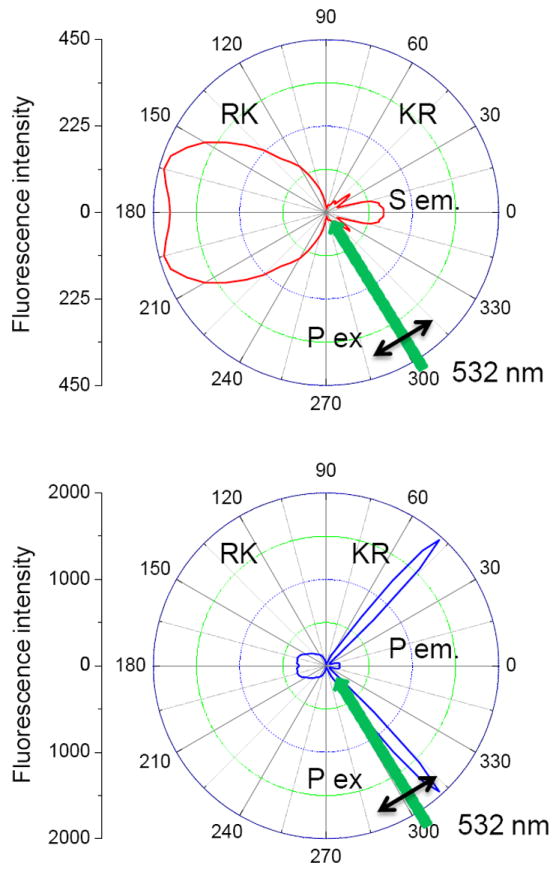
Angle-dependent emission intensities for RhB (at 569 nm) on the Tamm structure with KR illumination at 57 degrees. Top, S-polarized emission. Bottom, P-polarized emission. When plotted on the same scale the intensities at 0 degree, the S and P polarized emission intensities are nearly equal (see Figure 11).
Figure 11.
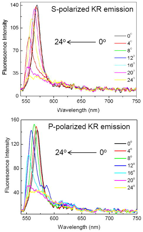
Tamm state-coupled emission of RhB with S- (top) and P-polarized (bottom) observation. P-polarized KR 532 nm illumination at 57 degrees.
We now consider the expected results for the Tamm structure with Rh6G, which has a slightly shorter emission maximum of 546 nm. Figure 12 shows simulated data for this wavelength. The decrease in wavelength from 569 to 546 nm shifts the Tamm resonance from 0 to 19 degrees (top). This result shows that the Tamm resonances are strongly dependent on wavelength and the Tamm resonance is similar for both S- and P-polarizations. The P-polarized reflectivity shows a decrease at 54 degrees, which is due to the usual surface plasmons. The middle panel shows that even when the wavelength and angle are changed the Tamm fields are still localized below the metal film in the uppermost dielectric layer. Similar field intensities are found for both S- and P-polarized illumination. The lower panel shows the field produced with illumination at the SPR angle of 54 degrees. In this case S-polarized emission does not couple to any specific mode, but a high field is obtained by P-polarized light. The SPR field is about 5-fold larger than the Tamm field, a result we found consistently for a number of wavelengths and angles. Referring back to Figure 3 we see that the Tamm resonances shifts away from 0 degrees at shorter wavelengths and only P-polarized KR illumination creates surface plasmons (Figure 3, lower right).
Figure 12.
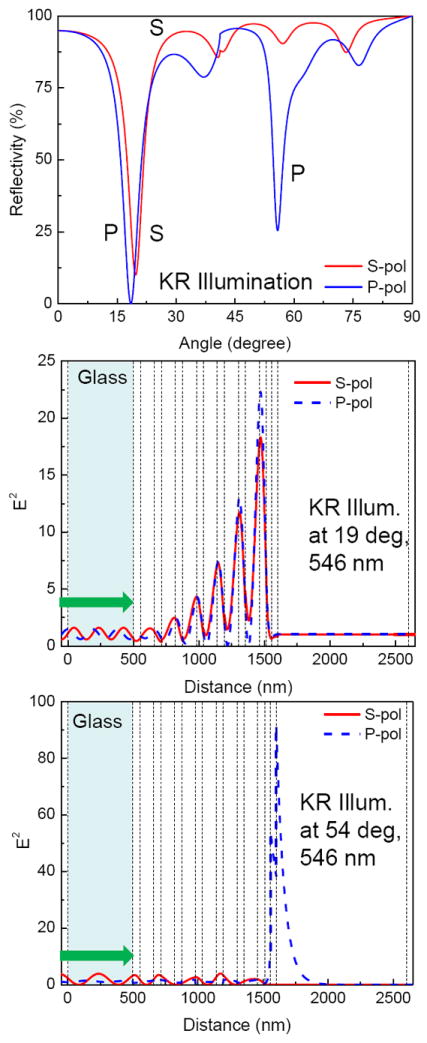
Reflectivity (top) and electric field intensities for 546 nm incident light on the Tamm structure with 18 (middle) and 54 (bottom) degrees.
Figure 13 shows the angle-dependent emission intensities of Rh6G at 546 nm with KR illumination (top). For this wavelength the TSCE direction is no longer perpendicular to the surface, but occurs at about 20 degrees from the normal. This is consistent with the angular shift calculated in Figure 12. The top panel also shows a second peak about 47 degrees from the normal. Since this emission is S-polarized it cannot be from coupling to surface plasmons. The origin of this peak can be seen from the dispersion plots in Figure 3 (lower left). Consider a horizontal line starting at 546 nm across the panel. This line intersects the Tamm state at about 17 degrees and additional dips at 47 degrees and at some larger angles. We attribute the intensity peak at 47 degrees in Figure 13 to this latter intersection point. We note that the intensity of the 47 degree peak is higher than at 17 degrees, but the resonance at 47 degrees appears to be weaker in Figure 3.
Figure 13.
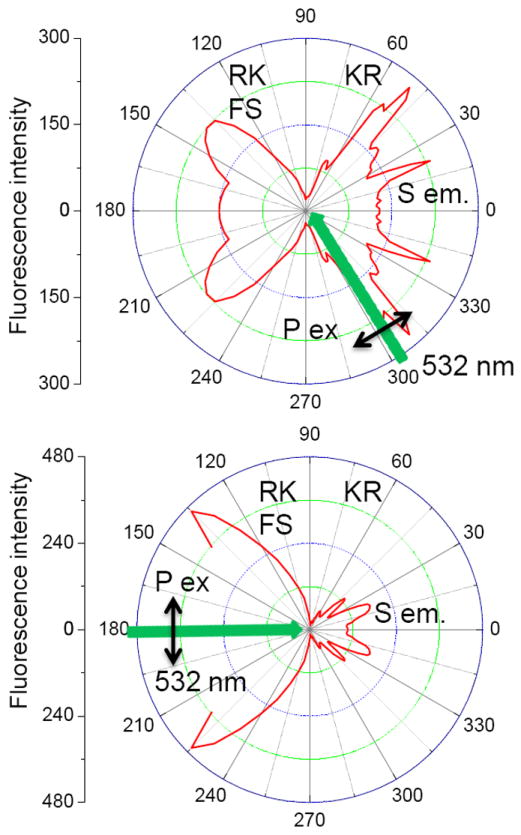
Angle-dependent S-polarized emission intensity for Rh6G at 546 nm using KR (top) and RK (bottom) illuminations. 532 nm P-pol incident light is used for excitation. The incident angles for KR and RK illuminations are 60 and 180 degrees, respectively.
The top and bottom panels of Figure 13 compare the Rh6G intensities with KR and RK excitation, respectively. There appears to be higher free-space emission with RK as compared to KR illumination. We believe this occurs because RK illumination provides relatively uniform excitation through the PVA layer whereas KR illumination excites fluorophores closer to the metal which are more strongly coupled to the Tamm state. We also noticed that the angular distribution of the TSCE is slightly different for KR or RK illumination. Our simulations showed slightly different reflectance spectra for KR and RK incidence (Figure 7 and Figure S2), but we did not expect the TSCE to depend on the mode of excitation. One possible explanation is KR excitation creates an excited state dipole population preferentially aligned normal to the surface, and RK illumination results in dipoles mostly parallel to the surfaces. Further studies are required to clarify this point.
We examined the emission spectra of Rh6G on the Tamm structures for various angles of observation. The emission spectra were surprisingly complex (Figure 14) showing two main bands near 550 and 650 nm. Similar spectra were found for both S- and P-polarized emission, demonstrating that these spectra are for TSCE and not SPCE which would be P-polarized. At first we were puzzled by these spectra, but they can be understood from the dispersion plots in Figure 3. Consider a vertical line in the lower left panel starting at 0 degrees. This line intersects a Tamm state at about 570 nm and again at about 660 nm. These emission maxima are seen in the spectra recorded at 0 degrees in Figure 14. Now consider a vertical line at a larger angle near 20 degrees. The vertical line now intersects the resonances at shorter wavelengths, which are close to the observed emission maxima at this observation angle. The longer wavelength peaks in the emission spectra appear to be coupling of the long wavelength side of the Rh6G emission to longer wavelength Tamm states. In contrast to SPCE, we expect TSCE to occur both away from the Tamm structure (RK) and through the Tamm structure (KR). We examined the emission spectra as seen from the RK direction (Figure 15). These spectra display spectral shifts which depend on the observation angle. The spectral shifts are less dramatic than seen with KR observation (Figure 14). Examination of the dispersion diagram with RK illumination (Figure 3, top panel) shows there are fewer resonances for RK than for KR illumination. Secondly, with RK illumination we expect a higher fraction of the emission to be from Rh6G which is not coupled to the structure. The spectral shifts in Figure 15 demonstrate that at least some of the RK emission is from coupling to the Tamm state. This suggestion is supported by the RK free-space emission spectra of the three probes which overlap the Tamm state (RhB, Rh5G on FL) and the absence of such spectral shifts for S101, which does not overlap the Tamm state (Figure S6).
Figure 14.
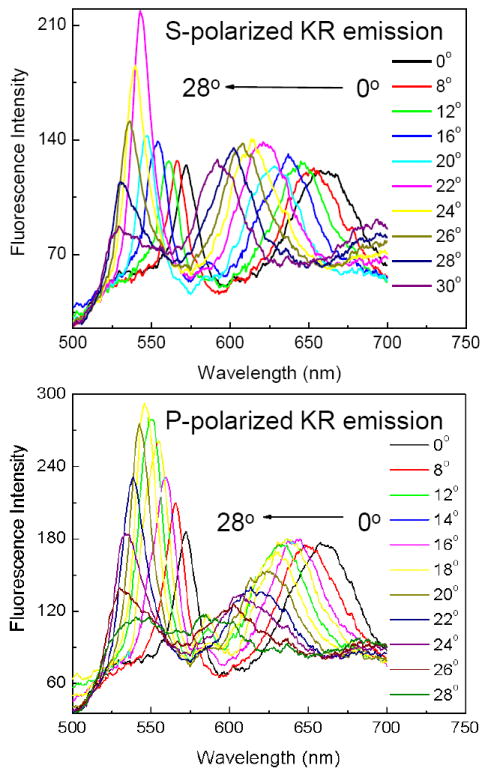
S- polarized (top) and P- polarized (bottom) KR emission spectra of Rh6G at different observation angles. 470 nm KR illumination at 60 degrees.
Figure 15.
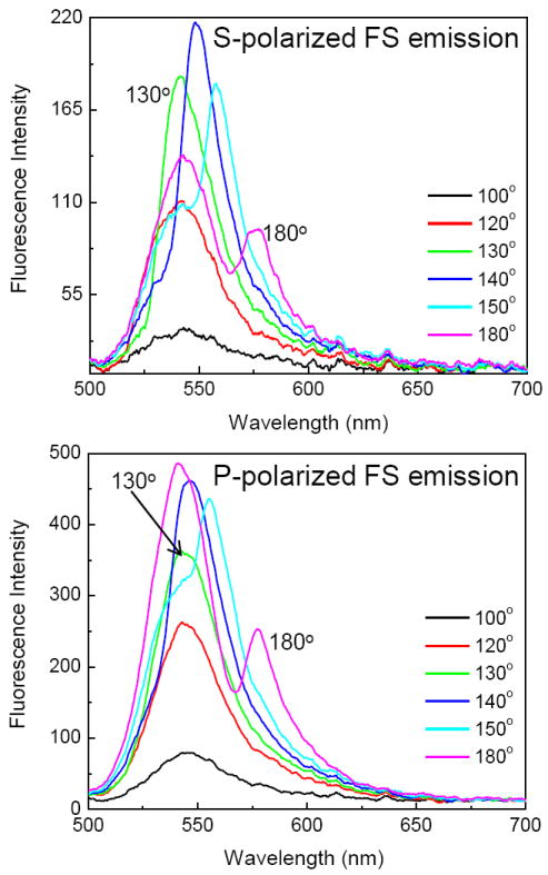
S- polarized (top) and P- polarized (bottom) free space emission from Rh6G on the Tamm structure. 470 nm KR illumination at 60 degrees.
It is informative to compare the angular intensity distribution for the four different probes. These distributions with KR illumination are shown in Figure 16. The angular distributions become wider when changing from RhB (569 nm) to Rh6G (546 nm) to Fl (520 nm). TSCE could not be observed for S101 at 600 nm. From S101 we could only observe KR emission at high angles and with P-polarization (not shown). The absence of TSCE from S101 is consistent with our dispersion calculations, which show a Tamm state does not exist in our structure for wavelengths above 570 nm (Figure 16, top panel). We also found that the angular distribution of the RK emission of the three fluorophores, but not S101, depends on the observation angle and also depends on the fluorophore and emission maximum (Figures S7 and S8). This result demonstrates that a significant fraction of the RK emission is the result of coupling to the Tamm state.
Figure 16.
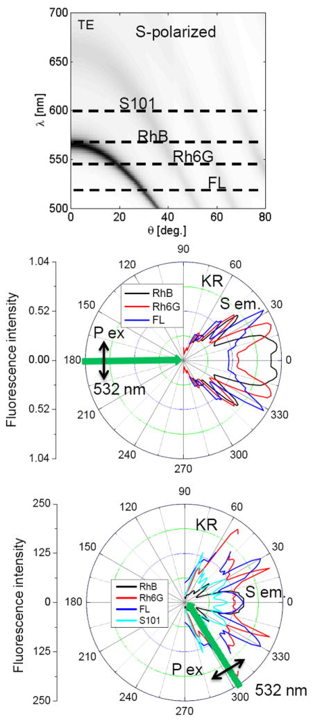
Calculated S-polarized dispersion diagram (top) and observed angular distribution of S101, RhB, Rh6G and Fluorescein (FL) on the Tamm structure. The reflectivity range is 0.0 to 1.0. Middle, using RK illumination. Bottom, KR illumination. The S-polarized coupled emission intensity for S101 using RK illumination is negligible.
Figure 17 summarizes the fluorescence emission maxima observed for Rh6G and FL. The emission maxima are in excellent agreement with the resonances found from the reflectivity calculations. It is interesting to note that the same emission maxima are noticed at the same observation angle, independent of the fluorophore. For instance, an emission maximum is observed at 570 nm for both Rh6G and FL at 0 degrees. Similarly, the same 600 nm emission maximum is observed for both Rh6G and Fl at 30 degrees. This result shows that the dependence of wavelength on angle represents the optical properties of the Tamm structure and not on the emission spectra of the fluorophores.
Figure 17.
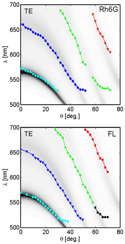
Calculated KR, S-polarized dispersion diagrams and observed emission maxima of Rh6G and Fluorescein (FL) on the Tamm structure. The reflectivity range is 0.0 to 1.0.
DISCUSSION
We believe that combined plasmonic-photonic structures offers opportunities in the next generation of devices for genomics, proteomics and diagnostics. These structures can provide for control of light and fluorescence at nanoscale dimensions [80-84]. We have recently described multi-layers of metals and dielectrics which can also provide directional emission normal to the surfaces [85-86]. In the present paper we describe a structure, which displays a Tamm state that can be accessible within the light cone or even with incidence normal to the surface. We found unambiguous evidence for TSCE normal to the surface and at small angles away from the normal axis.
While our Tamm structure displayed emission normal to the surfaces the intensities were not as high as we observed previously with SPCE [6-7]. We reasoned that the less intense TSCE is due to the Tamm electric fields being localized under the top metal layer, and mostly in the top dielectric layer, and due to the leaky nature of Tamm state in both directions. At first glance this field localization appears to be a negative aspect of TSCE. However, we have conceptualized several approaches which may increase the TSCE intensity (Figure 18). The top panel shows a BG with a nanoporous metal film about 100 nm thick, which is about twice the thickness used for SPR and SPCE. Nanoporous films of Al, Ag and Au can be readily formed by electrochemical or etching procedures [87-89]. The pore size in nanoporous metals (NPM) can easily be larger than typical biomolecules so that they could diffuse to NPM-dielectric interface and be exposed to the Tamm field. It is known that typical angle-dependent surface plasmon resonances can be observed with void volumes as large as 50% of the NPM [90-93]. Hence it seems likely that the Tamm states will continue to exist for a BG coated with a NPM film.
Figure 18.
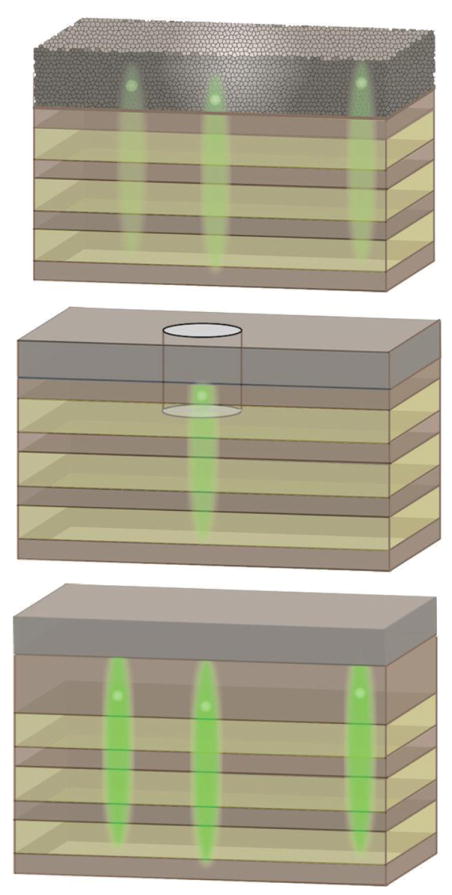
Potential structures for Tamm state-coupled emission with a nanoporous metal layer (top), nanoholes in a silver metal film (middle) and a Tamm structure with a thick dielectric layer below the metal film.
A second approach to using Tamm structures would be to include nanoholes which go through the top metal film and possibly into the underlying BG (Figure 18, middle). At present we are not aware of any reports on the presence or absence of Tamm states on such structures. However, typical nanoholes are about 100 to 200 nm in diameter and these sizes result in enhanced fluorescence [94-95]. Such nanohole-Tamm structures could find use in single strand DNA sequencing [96-97]. In this application the sample is illuminated from the bottom through the glass slide. The metal films for sequencing are usually about 200 nm thick because it is necessary to suppress emission from the sample side of the metal film which contains high concentrations of labeled nucleotides. A thicker metal film does not disrupt the Tamm state [74-75]. In fact we have already shown in simulations that compared to the 42 nm Ag film used in the report the Tamm field intensities increase over 3-fold if the metal thickness is increased to 125 or 900 nm (not shown). Another approach is to increase thickness of the top dielectric layer to make more room for the samples (Figure 18, bottom). This increase is possible because Tamm states were shown to exist with the top dielectric being up to 2 microns thick [98]. For all three structures shown in Figure 18 we expect that some of the TSCE to also be directed out the top of the structures (not shown). These considerations suggest that Tamm states can exist in a variety of metal. BG structures can be modified for a variety of sensing applications.
In conclusion we anticipate that structures which display both plasmonic and photonic modes will provide the opportunity for the next generation of simple and robust sensing devices.
Supplementary Material
Acknowledgments
We thank UMCP Fablab. This work was supported by NIH Grants RO1HG002655, RO1EB006521 and RO1HG005090. E. D. Thanks financial support from EU FP7 project BILOBA (Grant # 318035). The authors thank Dr. Kazik Nowaczyk for assistance with illustrations.
Footnotes
Supplementary material
Supplementary data associated with this article can be found, in the online version, at http://dx.doi.org
Publisher's Disclaimer: This is a PDF file of an unedited manuscript that has been accepted for publication. As a service to our customers we are providing this early version of the manuscript. The manuscript will undergo copyediting, typesetting, and review of the resulting proof before it is published in its final citable form. Please note that during the production process errors may be discovered which could affect the content, and all legal disclaimers that apply to the journal pertain.
References
- 1.Lakowicz JR. Radiative decay engineering: Biophysical and biomedical applications. Anal Biochem. 2001;298:1–24. doi: 10.1006/abio.2001.5377. [DOI] [PMC free article] [PubMed] [Google Scholar]
- 2.Lakowicz JR. Plasmonics in biology and plasmon-controlled fluorescence. Plasmonics. 2006;1:5–33. doi: 10.1007/s11468-005-9002-3. [DOI] [PMC free article] [PubMed] [Google Scholar]
- 3.Lakowicz JR. Radiative decay engineering 5: Metal-enhanced fluorescence and plasmon emission. Anal Biochem. 2005;337:171–194. doi: 10.1016/j.ab.2004.11.026. [DOI] [PMC free article] [PubMed] [Google Scholar]
- 4.Demchenko AP. Nanoparticles and nanocomposites for fluorescence sensing and imaging. Methods Appl Fluoresc. 2013;1:022001–1/28. doi: 10.1088/2050-6120/1/2/022001. [DOI] [PubMed] [Google Scholar]
- 5.Lakowicz JR, Shen Y, D’Auria S, Malicka J, Fang J, Gryczynski Z, Gryczynski I. Radiative decay engineering 2. Effects of silver island films on fluorescence intensity, lifetimes, and resonance energy transfer. Anal Biochem. 2002;301:261–277. doi: 10.1006/abio.2001.5503. [DOI] [PMC free article] [PubMed] [Google Scholar]
- 6.Lakowicz JR. Radiative decay engineering 3. Surface plasmon-coupled directional emission. Anal Biochem. 2004;324:153–169. doi: 10.1016/j.ab.2003.09.039. [DOI] [PMC free article] [PubMed] [Google Scholar]
- 7.Gryczynski I, Malicka J, Gryczynski Z, Lakowicz JR. Radiative decay engineering 4. Experimental studies of surface plasmon-coupled directional emission. Anal Biochem. 2004;324:170–182. doi: 10.1016/j.ab.2003.09.036. [DOI] [PMC free article] [PubMed] [Google Scholar]
- 8.Fort E, Gressillon S. Surface enhanced fluorescence. J Phys D Appl Physics. 2008;41:1–31. [Google Scholar]
- 9.Xie F, Drozdowicz-Tomisa K, Goldys EM. A method to assess modifications of fluorophore radiative rate by plasmonic structures. Chem Phys Letts. 2008;466:186–188. [Google Scholar]
- 10.Kroekenstoel EJA, Verhagen E, Walters RJ, Kuipers L, Polman A. Enhanced spontaneous emission rate in annular plasmonic nanocavities. Appl Phys Letts. 2009;95:63106-1–3. [Google Scholar]
- 11.Fu Y, Lakowicz JR. Modification of single molecule fluorescence near metallic nanostructures. Laser & Photonic Rev. 2009;3:221–233. doi: 10.1002/lpor.200810035. [DOI] [PMC free article] [PubMed] [Google Scholar]
- 12.Zhang J, Fu Y, Chowdhury MH, Lakowicz JR. Single-molecule studies on fluorescently labeled silver particles: Effects of particle size. J Phys Chem C. 2008;112:18–26. doi: 10.1021/jp074938r. [DOI] [PMC free article] [PubMed] [Google Scholar]
- 13.Anger P, Bharadwaj P, Novotny L. Enhancement and quenching of single-molecule fluorescence. Phys Rev Letts. 2006;96:113002–1/4. doi: 10.1103/PhysRevLett.96.113002. [DOI] [PubMed] [Google Scholar]
- 14.Kinkhabwala A, Yu Z, Fan S, Avlasevich Y, Mullen K, Moerner WE. Large single-molecule fluorescence enhancements produced by a bowtie nanoantenna. Nature Photonics. 2009;3:654–657. [Google Scholar]
- 15.Tam F, Goodrich GP, Johnson BR, Halas NJ. Plasmonic enhancement of molecular fluorescence. Nano Letts. 2007;7:496–501. doi: 10.1021/nl062901x. [DOI] [PubMed] [Google Scholar]
- 16.Chen Y, Munechika K, Giner DS. Dependence of fluorescence intensity on the spectral overlap between fluorophores and plasmon resonant single silver nanoparticles. Nano Letts. 2007;7:690–696. doi: 10.1021/nl062795z. [DOI] [PubMed] [Google Scholar]
- 17.Akbay N, Lakowicz JR, Ray K. Distance-dependent metal-enhanced intrinsic fluorescence of proteins using polyelectrolyte layer-by-layer assembly and aluminum nanoparticles. J Phys Chem C. 2012;116:10766–10773. doi: 10.1021/jp2122714. [DOI] [PMC free article] [PubMed] [Google Scholar]
- 18.Chang Y-H, Lu Y-C, Chou K-S. Enhancement of photoluminescence of different quantum dots by Ag@SiO2 core-shell nanoparticles. Materials Res Bull. 2013;48:2076–2078. [Google Scholar]
- 19.Li W, Zhang J, Zhou Y, Zhang P. Highly enhanced fluorescence of fluorophores inside a metallic nanocavity. Chem Commun. 2011;47:5834–5836. doi: 10.1039/c1cc11002k. [DOI] [PubMed] [Google Scholar]
- 20.Zhang J, Fu Y, Xu X, Lakowicz JR. Target molecule imaging on tissue specimens by fluorescent metal nanoprobes. J Biomed Optics. 2011;16:116004–1/6. doi: 10.1117/1.3644394. [DOI] [PMC free article] [PubMed] [Google Scholar]
- 21.Zhang J, Fu Y, Mahdavi F. Bimetallic nanoshells for metal-enhanced fluorescence with broad band fluorophores. J Phys Chem C. 2012;116:24224–24232. doi: 10.1021/jp3057527. [DOI] [PMC free article] [PubMed] [Google Scholar]
- 22.Zhang J, Gryczynski I, Grycynski Z, Lakowicz JR. Dye-labeled silver nanoshell-bright particle. J Phys Chem B. 2006;110:8986–8991. doi: 10.1021/jp057032z. [DOI] [PMC free article] [PubMed] [Google Scholar]
- 23.Fu Y, Zhang J, Lakowicz JR. Large enhancement of single molecule fluorescence by coupling to hollow silver nanoshells. Chem Commun. 1012;48:9726–9728. doi: 10.1039/c2cc34025a. [DOI] [PMC free article] [PubMed] [Google Scholar]
- 24.Norton SJ, Vo-Dinh T. Plasmonics quenching and enhancement of a fluorescing molecule outside and inside a silver metallic nanoshell. IEEE Trans Nanotech. 2011;10:1264–1284. [Google Scholar]
- 25.Jun YC, Huang KCY, Brongersma ML. Plasmonic beaming and active control over fluorescent emission. Nature Commun. 2011;2:283–289. doi: 10.1038/ncomms1286. [DOI] [PubMed] [Google Scholar]
- 26.Aouani H, Mahboub O, Bonod N, Devaus E, Popov E, Rigneault H, Ebbesen TW, Wenger J. Bright unidirectional fluorescence emission of molecules in a nanoaperature with plasmonic corrugations. Nano Letts. 2011;11:637–644. doi: 10.1021/nl103738d. [DOI] [PubMed] [Google Scholar]
- 27.King NS, Li Y, A-Orozco C, Brannan T, Nordlander P, Halas NJ. Angle- and spectral-dependent light scattering from plasmonic nanocups. Acs Nano. 2011;9:7254–7262. doi: 10.1021/nn202086u. [DOI] [PubMed] [Google Scholar]
- 28.Sun G, Khurgin JB, Yang CC. Impact of high-order surface plasmon modes of metal nanoparticles on enhancement of optical emission. Appl Phys Letts. 2009;956:171103–1/3. [Google Scholar]
- 29.Mertens H, Koenderink AF, Polman A. Plasmon-enhanced luminescence near noble-metal nanospheres: Comparison of exact theory and an improved Gersten and Nitzan model. Phys Rev B. 2007;76:115123–1/12. [Google Scholar]
- 30.Sun G, Khurgin JB, Soref RA. Practical enhancement of photoluminescence by metal nanoparticles. Appl Phys Letts. 2009;94:101103–1/3. [Google Scholar]
- 31.Jun YC, Kekatpure RD, White JS, Brongersma ML. Nanoresonant enhancement of spontaneous emission in metal-dielectric metal plasmon waveguide structures. Phys Rev B. 2008;78:153111–1/4. [Google Scholar]
- 32.D’Agostino S, Sala FD, Andreani LC. Dipole-excited surface plasmons in metallic nanoparticles: Engineering decay dynamics within the discrete-dipole approximation. Phys Rev B. 2013;87:205413–1/13. [Google Scholar]
- 33.Xie F, Drozdowicz-Tomsia K, Goldys EM. A method to assess modifications of fluorophore radiative rate by plasmonic structures. 2008;466:186–188. [Google Scholar]
- 34.Chowdhury MH, Pond J, Gray SK, Lakowicz JR. Systematic computational study of the effect of silver nanoparticle dimers on the coupled emission from nearby fluorophores. J Phys Chem C. 2008;112:11236–11249. doi: 10.1021/jp802414k. [DOI] [PMC free article] [PubMed] [Google Scholar]
- 35.Nabika H, Takase M, Nagasawa F, Murakoshi K. Toward plasmon-induced photoexcitation of molecules. J Phys Chem Letts. 2010;1:2470–2487. [Google Scholar]
- 36.Dionne JA, Atwater HA. Plasmonics: Metal-worthy methods and materials in nanophotonics. MRS Bulletin. 2012;37:717–724. [Google Scholar]
- 37.Schuller JA, Barnard ES, Cai W, Jun YC, White JS, Brongersma ML. Plasmonics for extreme light concentration and manipulation. Nature Materials. 2010;9:193–204. doi: 10.1038/nmat2630. [DOI] [PubMed] [Google Scholar]
- 38.Jain PK, El-Sayed MA. Plasmonic coupling in noble metal nanostructures. Chem Phys Letts. 2010;487:153–164. [Google Scholar]
- 39.Stockman MI. Nanoplasmonics: past, present, and glimpse into future. Optics Express. 2011;19:22029–22106. doi: 10.1364/OE.19.022029. [DOI] [PubMed] [Google Scholar]
- 40.Saleh BEA, Teich MC. Fundamentals of Photonics. 2. Wiley-Interscience; 2007. [Google Scholar]
- 41.Joannopoulos JD, Johnson SG, Winn JN, Meade RD. Photonic Crystals Molding the Flow of Light. 2. Princeton University Press; 2008. p. 286. [Google Scholar]
- 42.Wang H, Zhang KQ. Photonic crystal structures with tunable structure color as colorimetric sensors. Sensors. 2013;13:4192–4213. doi: 10.3390/s130404192. [DOI] [PMC free article] [PubMed] [Google Scholar]
- 43.Kurt P, Banerjee D, Cohen RE, Rubner MF. Structural color via layer-by-layer deposition: layered nanoparticle arrays with near-UV and visible reflectivity bands. J Material Chem. 2009;19:8920–8927. [Google Scholar]
- 44.Yablonovitch E. Inhibited spontaneous emission in solid-state physics and electronics. Phys Rev Letts. 1987;58:2059–2062. doi: 10.1103/PhysRevLett.58.2059. [DOI] [PubMed] [Google Scholar]
- 45.John S. Strong localization of photons in certain disordered dielectric superlattices. Phys Rev Letts. 1987;58:2486–2489. doi: 10.1103/PhysRevLett.58.2486. [DOI] [PubMed] [Google Scholar]
- 46.Kashyap R. Fiber Bragg Gratings, (Optics and Photonics Series) 2. Academic Press; 2009. p. 632. [Google Scholar]
- 47.Nikolaev IS, Lodahl P, Vos WL. Fluorescence lifetime of emitters with broad homogeneous line-widths modified in optical photonic crystals. J Phys Chem C. 2008;112:7250–7254. [Google Scholar]
- 48.Kubo S, Fujishima A, Sato O, Segawa H. Anisotropic accelerated emission of the chromophores in photonic crystals consisting of a polystyrene opal structure. J Phys Chem C. 2009;113:11704–11711. [Google Scholar]
- 49.Badugu R, Nowaczyk K, Descrovi E, Lakowicz JR. Radiative decay engineering 6: Fluorescence on one-dimensional photonic crystals. Anal Biochem. 2013;49:83–96. doi: 10.1016/j.ab.2013.07.021. [DOI] [PMC free article] [PubMed] [Google Scholar]
- 50.Ballarini M, Frascella F, Michelotti F, Digregorio G, Rivolo P, Paeder V, Musi V, Giorgis F, Descrovi E. Bloch surface waves-controlled emission of organic dyes grafted on a one-dimensional photonic crystals. Appl Phys Lett. 2011;99:043302. [Google Scholar]
- 51.Homola J, editor. Surface Plasmon Resonance Based Sensors. Vol. 251. Springer; New York: p. 37. [Google Scholar]
- 52.Brongersma ML, Kik PG, editors. Surface Plasmon Nanophotonics. Springer; New York: p. 268. [Google Scholar]
- 53.Tamm I. A possible binding of the electrons on a crystal surface. Zh Eksp Teor Fiz. 1933;3:34–35. [Google Scholar]
- 54.Born M, Wolf E. Principles of Optics. Cambridge University Press; 2002. p. 952. [Google Scholar]
- 55.Ashcroft NW, David Mermin N. Solid State Physics. Brooks/Cole; 1976. p. 826. [Google Scholar]
- 56.Kavokin AV, Shelykh IA, Malpuech G. Lossless interface modes at the boundary between two periodic dielectric structures. Phys Rev B. 2005;72:233102–1/4. [Google Scholar]
- 57.Kaliteevski M, Iorsh I, Brand S, Abram RA, Chamberlain JM, Kavokin AV, Shelykh IA. Tamm plasmon-polaritons: Possible electromagnetic states at the interface of a metal and a dielectric Bragg mirror. Phys Rev B. 2007;76:165415–1/5. [Google Scholar]
- 58.Gaspar-Armenta JA, Villa F. Photonic surface-wave excitation: photonic crystal–metal interface. J Opt Soc Am B. 2003;20:2349–2354. [Google Scholar]
- 59.Chem Z, Han P, Leung CW, Wang Y, Hu M, Chen Y. Study of optical Tamm states based on the phase properties of one-dimensional photonic crystals. Optics Express. 2012;20:21618–21626. doi: 10.1364/OE.20.021618. [DOI] [PubMed] [Google Scholar]
- 60.Kavokin A, Shelykh I, Malpuech G. Optical tamm states for the fabrication of polariton lasers. Appl Phys Letts. 2005;87:261005–1/3. [Google Scholar]
- 61.Sasin ME, Seisyan RP, Kalitteevski MA, Brand S, Abram RA, Chamberlain JM, Yu Egorov A, Vasil’ev AP, Mikhrin VS, Kavokin AV. Tamm plasmon polaritons: Slow and spatially compact light. Appl Phys Letts. 2008;92:25112-1–3. [Google Scholar]
- 62.Vukovic SM. Plasmonic Bragg reflector and tamm plasmon polaritons in metal-dielectric superlattices. Acta Phys Pol A. 2009;116:678–680. [Google Scholar]
- 63.Fang Y-t, Chen L-k, Zhu N, Zhou J. Tamm states of one-dimensional metal-dielectric photonic crystal. IET Opto. 2013;7:9–13. [Google Scholar]
- 64.Thevenaz L, Dicaire I, Chin S-H. Enhancing the light-matter interaction using slow light: towards the concept of dense light. Proc SPIE. 2012;8273:82731D–1/8. [Google Scholar]
- 65.Pedersen MEV, Rishej LS, Steffensen H, Xiao S, Mortensen NA. Slow-light enhanced optical detection in liquid-infiltrated photonic crystals. Opt Quant Electron. 2007;39:903–911. [Google Scholar]
- 66.Johnson PB, Christy RW. Optical constants of the noble metals. Phys Rev B. 1972;6:4370–4374. [Google Scholar]
- 67.Macleod HA. Thin-Film Optical Filters. IoP Publishers; Philadelphia: 2001. p. 641. [Google Scholar]
- 68.Elshabini-Riad AAR, Barlow FD. Thin Film Technology Handbook. Mc-Graw Hill; New York: 1997. pp. 1–1/11.50. [Google Scholar]
- 69.Heavens OS. Optical Properties of Thin Solid States. Dover Publications; New York: 1955. p. 261. [Google Scholar]
- 70.Sasin ME, Seisyan RP, Kalitteevski MA, Brand S, Abram RA, Chamberlain JM, Yu Egorov A, Vasil’ev AP, Mikhrin VS, Kavokin AV. Tamm plasmon polaritons: Slow and spatially compact light. Appl Phys Letts. 2008;92:251112–1/3. [Google Scholar]
- 71.Gryczynski I, Malicka J, Nowaczyk K, Gryczynski Z, Lakowicz JR. Effects of sample thickness on the optical properties of surface plasmon-coupled emission. J Phys Chem B. 2004;108:12073–12083. doi: 10.1021/jp0312619. [DOI] [PMC free article] [PubMed] [Google Scholar]
- 72.Maradudin AA, editor. Structured Surfaces as Optical Metamaterials. Cambridge University Press; 2011. p. 436. [Google Scholar]
- 73.Brongersma ML, Kik PG, editors. Surface Plasmon Nanophotonics. Springer; New York: 2008. p. 268. [Google Scholar]
- 74.Brand S, Kaliteevski MA, Abram RA. Optical tamm states above the bulk plasma frequency at a Bragg stack/metal interface. Phys Rev B. 2009;79:085416–1/4. [Google Scholar]
- 75.Du G, Cui L, Zhang L, Jiang H. Tamm plasmon polaritons in composite structures composed of the metal film and truncated photonic crystals. Appl Phys A. 2012;109:907–911. [Google Scholar]
- 76.Feng S, Elson JM, Overfelt PL. Transparent photonic band in metallodielectric nanostructures. Phys Rev B. 2005;72:085117–1/6. [Google Scholar]
- 77.He Y, Zhou H, Jin Y, He S. Plasmon induced transparency in a dielectric waveguide. Appl Phys Letts. 2011;99:043113–1/3. [Google Scholar]
- 78.Sclaora M, Bioemer MJ, Pethel AS, Dowling JP, Bowden CM, Manka AS. Transparent metallo-dielectric one-dimensional, photonic band-gap structures. J Appl Plys. 1988;83:2377–2383. [Google Scholar]
- 79.Tsang SH, Yu SF, Li XF, Yang HY, Liang HK. Observation of tamm plasmon polaritons in visible regime from ZnO/Al2O3 distributed Bragg reflector - Ag interface. Optics Commun. 2011;284:1890–1892. [Google Scholar]
- 80.Battal E, Okyay AK. Metal-dielectric-metal plasmonic resonators for active beam steering in the infrared. Optics Letts. 2013;38:983–985. doi: 10.1364/OL.38.000983. [DOI] [PubMed] [Google Scholar]
- 81.Iorsh I, Poddubny A, Orlov A, Belov P, Kivshar YS. Spontaneous emission enhancement in metal-dielectric metamaterials. Phys Letts A. 2012;376:183–187. [Google Scholar]
- 82.Jang MS, Atwater H. Plasmonic rainbow trapping structures for light localization and spectrum splitting. Phys Rev Letts. 2011;107:20-7401–1/5. doi: 10.1103/PhysRevLett.107.207401. [DOI] [PubMed] [Google Scholar]
- 83.Zhou L, Huang C, Wu S, Yin X, Wang Y, Wang Q, Zhu Y. Enhanced optical transmission through metal-dielectric multilayer gratings. Appl Phys Letts. 2010;97:011905–1/3. [Google Scholar]
- 84.Tian M, Lu P, Chen L, Liu D, Peyghambarian N. Plasmonic bragg reflectors based on metal-embedded MIM structure. Optics Commun. 2012;285:5122–5127. [Google Scholar]
- 85.Choudhury SD, Badugu R, Nowaczyk K, Ray K, Lakowicz JR. Tuning fluorescence direction with plasmonic metal-dielectric-metal substrates. J Phys Chem Letts. 2013;4:227–232. doi: 10.1021/jz301867b. [DOI] [PMC free article] [PubMed] [Google Scholar]
- 86.Choudhury SD, Badugu R, Ray K, Lakowicz JR. Steering fluorescence emission with metal-dielectric-metal structures of Au, Ag, and Al. J Phys Chem C. 2013 doi: 10.1021/jp4051066. in press. [DOI] [PMC free article] [PubMed] [Google Scholar]
- 87.Erlebacher J, Aziz MJ, Karma A, Dimitrov N, Sieradzki K. Evolution of nanoporosity in dealloying. Nature. 2001;410:450–456. doi: 10.1038/35068529. [DOI] [PubMed] [Google Scholar]
- 88.Zhang Z, Wang Y, Qi Z, Zhang W, Qin J, Frenzel J. Generalized fabrication of nanoporous metals (Au, Pd, Pt, Ag, and Cu) through chemical dealloying. J Phys Chem C. 2009;113:12629–12636. [Google Scholar]
- 89.Ding Y, Erlebacher J. Nanoporous metals with controlled multimodal pore size distribution. J Am Chem Soc. 2003;125:7772–7773. doi: 10.1021/ja035318g. [DOI] [PubMed] [Google Scholar]
- 90.Yu F, Ahl S, Caminade A-M, Majoral J-P, Knoll W, Erlebacher J. Simultaneous excitation of propagating and localized surface plasmon resonance in nanoporous gold membranes. Anal Chem. 2006;78:7346–7350. doi: 10.1021/ac060829h. [DOI] [PubMed] [Google Scholar]
- 91.Abdulhalim I, Lakhtakia A, Lahav A, Zhang F, Xu J. Porosity effect on surface plasmon resonance from metallic sculptured thin films. SPIE Proc. 2008;7041:7041–11. [Google Scholar]
- 92.Shalabney A, Lakhtakia A, Abdulhalim I, Lahav A, Patzig C, Hazek I, Karabchevsky A, Rauschenbach B, Zhang F, Xu J. Surface plasmon resonance from metallic columnar thin films. Photonics and Nanostructures. 2009;7:176–185. [Google Scholar]
- 93.Zhou H, Yang G, Wang K, Long H, Lu P. Multiple optical Tamm states at a metal-dielectric mirror interface. Optics Letts. 2010;35:4112–4114. doi: 10.1364/OL.35.004112. [DOI] [PubMed] [Google Scholar]
- 94.Wenger J, Gerard D, Aouani H, Rigneault H. Nanoaperture-enhanced signal-to-noise ratio in fluorescence correlation spectroscopy. Anal Chem. 2009;81:834–839. doi: 10.1021/ac8024015. [DOI] [PubMed] [Google Scholar]
- 95.Genet C, Ebbesen TW. Light in tiny holes. Nature. 2007;445:39–46. doi: 10.1038/nature05350. [DOI] [PubMed] [Google Scholar]
- 96.Eid J, et al. Real-time DNA sequencing from single polymerase molecules. Science. 2009;323:133–138. doi: 10.1126/science.1162986. [DOI] [PubMed] [Google Scholar]
- 97.Metzker ML. Sequencing technologies - the next generation. Nature Reviews. 2010;11:32–46. doi: 10.1038/nrg2626. [DOI] [PubMed] [Google Scholar]
- 98.Zhou H, Yang G, Wang K, Long H, Lu P. Multiple optical Tamm states at a metal-dielectric mirror interface. Optics Letts. 2010;35:4112–4114. doi: 10.1364/OL.35.004112. [DOI] [PubMed] [Google Scholar]
Associated Data
This section collects any data citations, data availability statements, or supplementary materials included in this article.


