Abstract
Introduction
The High Tibial Osteotomy (HTO) is a reliable procedure in addressing uni- compartmental arthritis with associated coronal deformities. With osteotomy of the proximal tibia, there is a risk of altering the tibial slope in the sagittal plane. Surgical techniques continue to evolve with trends towards procedure reproducibility and simplification. We evaluated a modification of the Arthrex iBalance technique in 18 paired cadaveric knees with the goals of maintaining sagittal slope, increasing procedure efficiency, and decreasing use of intraoperative fluoroscopy.
Methods
Nine paired cadaveric knees (18 legs) underwent iBalance medial opening wedge high tibial osteotomies. In each pair, the right knee underwent an HTO using the modified technique, while all left knees underwent the traditional technique. Independent observers evaluated postoperative factors including tibial slope, placement of hinge pin, and implant placement. Specimens were then dissected to evaluate for any gross muscle, nerve or vessel injury.
Results
Changes to posterior tibial slope were similar using each technique. The change in slope in traditional iBalance technique was -0.3° ±2.3° and change in tibial slope using the modified iBalance technique was -0.4° ±2.3° (p=0.29). Furthermore, we detected no differences in posterior tibial slope between preoperative and postoperative specimens (p=0.74 traditional, p=0.75 modified).
No differences in implant placement were detected between traditional and modified techniques. (p=0.85). No intraoperative iatrogenic complications (i.e. lateral cortex fracture, blood vessel or nerve injury) were observed in either group after gross dissection.
Discussion & Conclusions
Alterations in posterior tibial slope are associated with HTOs. Both traditional and modified iBalance techniques appear reliable in coronal plane corrections without changing posterior tibial slope. The present modification of the Arthrex iBalance technique may increase the efficiency of the operation and decrease radiation exposure to patients without compromising implant placement or global knee alignment.
Introduction
High tibial osteotomies (HTOs) have been used effectively for decades1'3. Coventry and Insall popularized HTOs in the 1970's -1980's4,5 and they continue to prove a reliable treatment for medial compartment osteoarthritis with associated varus deformity6,7. Today, medial opening wedge HTOs are most commonly indicated in younger patients (<60 years) who display medial compartment osteoarthritis with an associated varus limb alignment and have preserved knee motion4. There are several commercially available systems and described techniques to guide surgeons in performing HTOs. In general, most current techniques advocate similar principles including medial-sided opening wedge5 osteotomies, incomplete osteotomies (i.e. incomplete proximal tibial bone cut resulting in plastic deformation of the lateral cortex) and rigid medial fixation6. The Arthrex iBalance system incorporates these core principles and has demonstrated clinical efficacy and safety11,12.
Alterations in posterior slope may occur with HTOs, both with closing wedge and opening wedge techniques. Careful attention must be paid to posterior tibial slope as this is related to global knee stability and function13,14. In particular, opening wedge osteotomy is related to increasing the posterior tibial slope and creating a relative patella baja. These alterations in posterior tibial slope have been demonstrated in clinical series with the use of medial opening wedge HTOs15. The ability of a given technique to accurately correct alignment while maintaining tibial slope is, therefore, an important consideration.
The iBalance technique utilizes several radiographs and has several intraoperative steps and is reliant on both AP and lateral fluoroscopic views12. The safety of patients as well as the operating surgeon are concerns that warrant merit in the setting of fluoroscopy-reliant procedures16, 17. There are suggestions that thyroid cancer and cataracts are potential complications of prolonged radiation exposure to orthopaedic surgeons.18, 19 Efficient use of operative time is also thought to decrease chances of complications and improve patient safety. Given this, an optimal technique would allow for ideal implant placement, decrease operative time and limit intraoperative radiation to both the patient and surgeon.
The purpose of this study is to validate a modified technique for the Arthrex iBalance HTO system. The goals of the technique modification are to increase efficiency and decrease use of intraoperative fluoroscopy. We assessed a modified operative HTO protocol and compared it to the standard technique using paired cadaveric knees. The principle outcome parameters assessed number of procedure steps, amount of fluoroscopy used, implant placement and maintenance of tibial slope. We hypothesize that this technical modification will increase efficiency and decrease fluoroscopy utilization without comprising implant placement or sagittal alignment.
Materials and Methods
Nine paired cadaveric knees (18 legs) (ages 44-72, mean 57.3) were utilized. In each pair, the left knee underwent a HTO using the traditional iBalance technique20, while the contralateral knee underwent the modified technique. [Appendix] All HTOs were performed by two experienced orthopaedic surgeons (AA and TB).
Modifications to the iBalance Technique:
Standard preoperative planning and correction calculations were carried out in both groups. The aim of each correction was to direct the mechanical axis through a point representative of 62.5% of the tibial plateau (medial = 0% to lateral = 100%).
The surgical incision and approach including periosteal elevation, posterior dissection of the popliteus and identification of the retropatellar space in the modified technique was identical to the standard procedure. In the new modified technique, the next step is obtaining an optimal AP fluoroscopy view is obtained with the leg in 20-30° of flexion [Figure 1]. The view must be on axis (i.e. looking down) the medial plateau's posterior tibial slope, and have neutral rotation so that the lateral tibial cortex intersects the mid-portion of the fibular head at its widest point. With the optimized AP image, there was no need to switch between AP and Lateral views throughout the procedure using the modified technique and no lateral view was needed throughout the procedure. The neurovascular (NV) shield was then assembled and placed posteriorly 15° relative to the tibial plateau, and confirmed by AP fluoroscopy. Assembly of the adjustable base, keyhole guide and alignment guide was performed and the patellar tendon protector was placed. The medial aspect locator was positioned 2.5 cm distal to the joint line, and the AM tab was placed on the anteromedial surface of the tibia. Using the four circles in the adjustable base, the size of the implant and instrumentation was confirmed using a perfect AP view [Figure 1]. The new trocar fixation pin was then placed, and the hinge pin was inserted after assuring the distance from the pin to lateral plateau was at least 1.25x greater than the distance from the hinge pin to the nearest lateral cortex (x) to prevent propagation of the osteotomy to the joint surface. A second new trocar fixation pin was then inserted through the anteromedial hole in the base, and the alignment handle was removed. The remaining steps including drilling of keyholes, application of the cutting guide, osteotomy, installation of Opening Jack, grafting, seating the implant placement and anchors was performed identically in the traditional and modified iBalance groups.
Figure 1. Optimal AP fluoroscopy view obtained with leg in 20-30° of flexion. Note, the view looks down the lateral plateau's slope. Note, also, the knee is in neutral rotation with the lateral cortex intersecting the mid-portion of the fibular head. This view is essential in carrying out the modified iBalance technique.
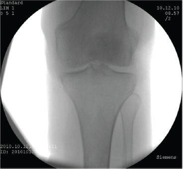
Overall, the technique modification reduces the fluoro images required. By obtaining a perfect AP view, two of the nine total steps were eliminated from the setup.
Hinge Pin Placement
Following the procedures, gross dissection was carried out to assess the placement of the hinge pin. Careful measurements were performed calculating the distances between the hinge pin and tibial plateau and hinge pin and lateral cortex. Measurements were performed by three independent observers. Traditional and modified techniques were directly compared using two-tailed student's t-tests.
Implant Placement
The placement of the implant was assessed relative to the medial tibial cortex. Measurements quantifying implant overhang (or step-off) relative to the posteromedial tibial cortex were made in millimeters. Measurements were performed and compared in both standard and modified groups.
Assessment of Tibial Slope
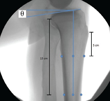
The ability of the modified technique to maintain native posterior tibial slope was also assessed. Posterior tibial slope was measured on pre-operative lateral radiographs in all specimens. These measurements were compared to post-procedure lateral radiographs after final implant placement. All digitized fluoroscopic images were exported to JPEG files for independent observer measurements. Slope was assessed by first defining the proximal tibia's anatomic axis (PTAA). [Figure 2] The PTAA was determined by identifying the anteroposterior diameter of the tibia at 5cm distal to the tibial tubercle and 15 cm distal to the joint line, and dividing these distances by two. Next, a line connecting these two half-way reference points was extended proximally to the level of the tibial plateau. Secondly, a line connecting the highest-most points of the anterior medial plateau and posterior medial plateau was drawn. This technique for measuring tibial slope in the setting of HTO's has been previously described21-23. The angle between these two lines was quantified using Adobe Photoshop 6.0 (Adobe Systems, Inc. San Jose, CA). Differences in posterior slope (pre-procedure slope minus post-procedure slope) between standard and modified techniques were compared using two-tailed student's t-tests. Interclass correlation coefficients were also calculated.
Figure 2. First, the PTAA was determined by identifying the anteroposterior diameter of the tibia at 5cm distal to the tibial tubercle and 15cm distal to the joint line, and dividing these distances by two. Next, a line connecting these two half-way reference points was extended proximally to the level of the tibial plateau, then posteriorly at a 90-degree angle. Secondly, a line connecting the highest-most points of the anterior medial plateau and posterior medial plateau was drawn. The posterior tibial slope was then measured, and represented by the “theta” in the above image.
After each procedure and final imaging, each specimen was dissected to inspect for injuries to muscle, nerves, blood vessels, and to evaluate for any unexpected fractures.
Results
Implant Placement
The mean distance from the hinge (perfect circle) to ridge in knees undergoing the traditional iBalance technique was 14.8 ± 3.52mm (range 10.9 mm to 18.6 mm). The mean distance from the hinge (perfect circle) to ridge in knees undergoing the modified iBalance technique was 15.1 ± 2.84 mm (range 10.2 mm to 19.2 mm). There were no significant differences observed between the two groups (p=0.85).
Tibial Slope
The preoperative posterior tibial slope values were similar in paired knees. Preoperatively, the mean posterior tibial slope in the traditional group was 7.9° ± 1.2° compared to 8.1° ± 1.6° in the modified group (p=0.8). There were no significant differences in postoperative tibial slope between the traditional (7.6° ± 2.3°) and modified (7.7° ± 3.2°) groups (p=0.9). The mean difference in pre-procedure and post-procedure posterior tibial slope observed using the traditional iBalance technique was -0.3° ±2.3°. The mean difference in pre-procedure and post-procedure posterior tibial slope observed using the modified iBalance technique was -0.4° ±2.3°. No significant differences were noted between the traditional and modified groups in terms of mean difference between slopes (p=0.9). Both the traditional and modified groups maintained native posterior tibial slope as there were no detected differences in posterior tibial slope between preoperative and postoperative specimens (p=0.74 traditional, p=0.75 modified). Interclass correlation coefficients were calculated to be 0.84 and 0.62 in the pooled preoperative and postoperative measurements, respectively.
Table 1.
Mean measurements of the 3 independent observers in assessment of preoperative and postoperative posterior tibial slope measurements. Note, no significant changes in posterior tibial slope occurred with placement of iBalance HTOs using either traditional or modified techniques.
| Modified iBalance Technique | |||
|---|---|---|---|
| Donor | Pre-Op Slope (°) | Post-Op Slope (°) | Slope Change (°) |
| 1306095 R | 4.6 | 3.1 | -1.5 |
| 1306118 R | 9.4 | 11.9 | 2.5 |
| 1306119 R | 8.1 | 3.6 | -4.6 |
| 1306121 R | 8.8 | 8.4 | -0.3 |
| 1306126 R | 6.9 | 7.9 | 1.0 |
| 1306140 R | 8.7 | 9.2 | 0.5 |
| 1306142 R | 9.2 | 11.8 | 2.6 |
| 1306145 R | 7.4 | 5.4 | -1.9 |
| 1306173 R | 9.7 | 8.0 | -1.8 |
| Average | 8.1 | 7.7 | -0.4 |
| St Dev | 1.6 | 3.2 | 2.3 |
| Traditional iBalance Technique | |||
|---|---|---|---|
| Donor | Pre-Op Slope (°) | Post-Op Slope (°) | Slope Change (°) |
| 1306095 L | 6.6 | 9.7 | 3.1 |
| 1306118 L | 9.1 | 7.6 | -1.5 |
| 1306119 L | 6.7 | 5.0 | -1.7 |
| 1306121 L | 7.4 | 8.4 | 1.0 |
| 1306126 L | 8.0 | 8.1 | 0.1 |
| 1306140 L | 10.1 | 10.8 | 0.7 |
| 1306142 L | 6.9 | 9.1 | 2.2 |
| 1306145 L | 7.5 | 3.4 | -4.0 |
| 1306173 L | 8.8 | 6.2 | -2.5 |
| Average | 7.9 | 7.6 | -0.3 |
| St Dev | 1.2 | 2.3 | 2.3 |
| P Value | 0.8 | 0.9 | 0.9 |
Table 2.
Interclass Correlation Coefficients calculated by pooling all preoperative posterior tibial slopes, and comparing the three readers. The ICCs demonstrated indicate high observer agreement.
| Pre-Operative Posterior Tibial Slope Measurements | |
| ICC (mean) | 0.8394 |
| Post-Operative Posterior Tibial Slope Measurements | |
| ICC (mean) | 0.6209 |
Dissection
Injuries to the popliteus muscle were identified in 3 specimens (2 traditional technique specimens and 1 modified technique specimen). There were no identified injuries to nerve, blood vessels and no identified peri-implant or lateral cortex fractures in either of the two groups.
Discussion
In this study, we evaluated a novel technique modification for the Arthrex iBalance HTO system. The modified technique used nearly one-third less fluoroscopic views during setup, and eliminated two of the nine steps required to align instrumentation for the iBalance HTO. After performing HTOs with the modified technique, we critically analyzed hinge pin placement and maintenance of posterior tibial slope and compared this to traditional iBalance techniques. Modifications to HTO techniques continue to evolve. Current trends are leading to technique simplification. Principle objectives when modifying an operative technique should be to increase patient safety and procedure efficiency.
This technique offers protection of the NV structures with the posterior tibial retractor anterior to the popliteus muscle, and the hinge pin laterally. After dissection, in only 2 specimens there was some injury to the popliteus muscle belly, but no evidence of any NV injury or penetration deep to the popliteus.
The technique modification lead to less fluoroscopy images necessary for completion of the iBalance HTO procedure. This is beneficial in two ways: efficiency of the operation and decreasing radiation exposure. Patient, surgeon, and surgical team safety should always be considered during fluoroscopy reliant procedures7. Techniques used to prevent excessive radiation exposure include wearing lead, keeping a safe distance and wearing protective eyewear. Improvements to techniques such as the modification presented provide an additional avenue to avoiding excessive radiation.
With decreased fluoroscopic views (specifically lateral views), the ability of the new technique to provide adequate and safe implant placement was a potential concern. We found no differences in hinge pin or final component placement between the traditional and modified groups. Hinge pin placement is important and when placed improperly the lateral cortex may be at risk for fracture. Intraoperative and postoperative fractures of the lateral cortex, when combined, have been reported in up to 8.6% of cases8. We observed no cases of intraoperative lateral cortex fracture in either the traditional or modified techniques in the present study. Given this technique modification, we aimed to assure safety in hinge pin placement and therefore avoiding iatrogenic fracture to the lateral cortex. The modified technique compared well with the traditional technique in terms of hinge pin placement, final component placement, and absence of lateral cortex fracture.
Maintenance of posterior tibial slope is an important consideration in tibial osteotomies as slope ties closely to knee stability13,14. Careful attention should be paid to preoperative sagittal knee alignment, especially in the setting of cruciate injury and/ or knee instability. Population norms for preoperative tibial slope ranges from 0° to 18°26. This compares well with the present cohort who averaged 8.0° of posterior tibial slope. Posterior tibial slope has been demonstrated by Brouwer et al to differ by almost 2.4° after medial opening wedge osteotomies15. Posterior tibial slope in our study decreased by an average of 0.4 degrees with the modified technique, and 0.3 degrees with the traditional technique; these differences in posterior tibial slope were not statistically significant. There were no significant differences in post-procedure posterior tibial slope between groups (p=0.9). Therefore, tibial slope was adequately maintained using this technique modification as changes to posterior tibial slope were insignificant in both groups.
The use of paired cadaveric knees, experienced orthopaedic surgeons and independent observers analyzing data were strengths of the present study. A weakness of the study is evaluated only one surgical technique. Therefore, findings may not be generalizable to all opening wedge HTO techniques.
Conclusions
Both traditional and modified iBalance techniques appear reliable and reproducible in coronal plane corrections without changing posterior tibial slope. The present modification of the Arthrex iBalance technique may increase the efficiency of the operation and decrease radiation exposure to patients without compromising implant placement or global knee alignment.
Appendix
New Modified Arthrex iBalance HTO Surgical Technique
Objective Validating the New Modified Surgical Technique
Preoperative Planning
Using the full-length, standing A/P radiograph, a line is drawn from the center of the femoral head to the center of the tibial-talar joint. This demonstrates the patient's mechanical axis. Another line is drawn from the center of the femoral head to a point midway in the lateral knee joint. A final line is drawn from the center of the tibial-talar joint to the same point in the lateral knee joint. The angle formed by the intersection of these two lines determines the degree of correction required to return the patient's mechanical axis to the point of intersection on the lateral side. Prior to final fixation, the alignment will be verified by external examination and fluoroscopy. This point is located at 62.5% of the width of the proximal tibia (i.e., 80 mm [width of proximal tibia] x. 625 = 50 mm).
Surgical Approach
Step 1
Plan a longitudinal incision midway between the tibial tubercle and the posterior border of the tibia. Start the incision just distal to the joint line and extend distally 7-9 cm.
Step 2
Clear/dissect tissue to the level of the pes/Sartorius fascia. Plan an L-shaped, inverted L-shaped, or vertical incision through the periosteum and upper aspect of the Sartorius attachment on the pes anserine bursa. If inverted L-shaped incision was chosen the inverted portion of the L-shaped incision should be at least 1cm distal to the joint line and parallel to the tibial slope to ensure avoidance of the joint space.
Step 3
Identify the retropatellar tendon space and expose with the Cobb Elevator. Partially elevate the proximal aspect of the pes anserine tendons from their distal insertion through the periosteal incision. Sharply dissect deeply to the proximal and anterior fibers of the superficial MCL. The Cobb Elevator may be used to complete the dissection posterior and distal.
Step 4
Advance the Posterior Elevator along the medial aspect of the tibia to the posterior border. Slide the tip of the elevator deep to the popliteus musculature, fascia tissue and periosteum. From the posterior border, continue to advance the elevator deep to the popliteus musculature and toward the fibular head. When fully inserted, the elevator tip should rest under the popliteus muscle. Remote the elevator and palpate along the posterior margin of the tibia to ensure adequate elevation of the popliteus musculature, fascia and periosteum.
Setup the Fluoroscope as Follows
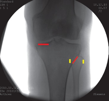
Large C-arm must approach the patient from the lateral side of the operative knee for optimal maneuverability and viewing. Support the leg in a fixed position 20-30 degrees of flexion.
Position fluoroscopes monitor such that it can be viewed from the operative field.
Adjust the rotation and alignment of the image on the fluoroscope monitor such that the image corresponds to the actual positions of the femur, tibia, anterior and posterior knee.
Establish the tibial AP view focusing on aligning and maintaining two key points:
Medial Tibial Plateau: Align the posterior medial tibial plateau with the anterior medial tibial plateau until they appear as a single line.
Lateral Tibial Cortex: Align the lateral tibial cortex rotationally until it crosses the widest point of the fibular head at approximately 30-50%
Step 5
Assemble the NV Shield and Handle. Insert the NV Shield through the elevated sleeve. Ensure that the tip of the NV Shield remains in contact with the bone surface during the entire insertion in the same manner as used with the Posterior Elevator. When fully inserted, the NV Shield tip should rest deep to the popliteus muscle. Confirm the NV Shield position is oriented approximately 15° from the tibial plateau with the AP fluoroscopic view described above. Important to use the right size NV shield in order to ensure adequate soft tissue elevation posteriorly throughout the desired length of the osteotomy. Remove the NV Shield and Handle.
Step 6
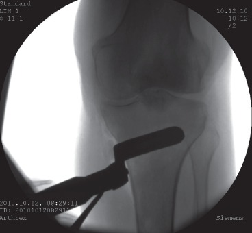
Assemble the Adjustable Base, Keyhole Guide, and Alignment Handle. Grasp the Alignment Handle and insert the Base and Keyhole Guide through the incision onto the proximal tibia. Slide the patellar tendon Protector into the exposed deep infrapatellar bursa, deep to the patellar tendon, and proximal to the tibial tubercle. Position the Medial Aspect Locator approximately 2.5cm distal to the joint line on the medial aspect of the tibia. Position the AM Tab onto the anteromedial surface of the tibia.
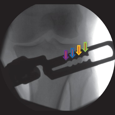
With the fluoroscopic AP view described above, the size of the iBalance HTO implant and instrumentation is confirmed. The 4 holes/ circles on the Adjustable Base illustrate the 4 potential (SM,MD,LG,XL) end/hinge points of the osteotomy. Once the sizing is confirmed, assemble the Hinge Pin Aimer, Biplanar Alignment Mount, and Hinge Pin Aimer Collet Nut onto the Adjustable Base and set to the determined size(SM,MD,LG,XL).
Step 7
Place the New Trocar tipped Fixation Pin into the anterior fixation pin hole on the Adjustable Base. Do not fixate into bone.
Maintaining the AP fluoroscopic view described above. Check to ensure the following conditions are met:
The Medial Aspect Locator is directly against the medial aspect of the tibia approximately 2.5cm distal to the joint line.
The AM Tab is against the anteromedial surface of the tibia.
Maintaining the Medial Aspect Locator and AM Tab against the cortices, the instrumentation is aligned to the specific AP fluoroscopic view described above until the Hinge Pin Hole appears as a complete/perfect circle. Confirm that the distance from the Hinge Pin to the lateral plateau is at least 1.25 times greater than the distance from the Hinge Pin to the nearest lateral cortex.
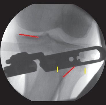
Insert already placed New Trocar Fixation Pin into bone via Mallet until the flange on the Fixation Pin seats against the base.
If the Hinge Pin hole is too close to the lateral plateau, adjust the position by rotating it around the frontal Fixation Pin, keeping the Medial Post and the AM Tab in contact with bone. This will lower the Hinge Pin hole away from the tibial plateau. If the Hinge Pin hole remains too close to the intra-articular surface, reevaluate the initial posotion of the instrumentation and return to the beginning of Step 7.
Insert a second New Trocar Fixation Pin through the anteromedial hole in the Base. Remove the Alignment Handle.
***Refer to the iBalance HTO Surgical Technique for the rest of the procedure***
References
- 1.Jackson JP, Waugh W. Tibial Osteotomy for Osteoarthritis of the Knee. Proc R Soc Med. 1960;53(10):888. doi: 10.1177/003591576005301026. Oct. [DOI] [PMC free article] [PubMed] [Google Scholar]
- 2.Jackson JP, Waugh W, Green JP. High tibial osteotomy for osteoarthritis of the knee. J Bone Joint Surg Br. 1969;51(1):88–94. Feb 1. [PubMed] [Google Scholar]
- 3.Jackson J. Osteotomy for osteoarthritis of the knee. J Bone Joint Surg Br. 1958;40:826. doi: 10.1302/0301-620X.43B4.746. [DOI] [PubMed] [Google Scholar]
- 4.Coventry MB. Upper tibial osteotomy for gonarthrosis. The evolution of the operation in the last 18 years and long term results. Orthop Clin North Am. 1979;10(1):191–210. Jan. [PubMed] [Google Scholar]
- 5.Insall JN, Joseph D, Msika C. High tibial osteotomy for varus gonarthrosis. J Bone Joint Surg Am. 1984;66:1040–1048. [PubMed] [Google Scholar]
- 6.Sprenger TR, Doerzbacher JF. Tibial osteotomy for the treatment of varus gonarthrosis. Survival and failure analysis to twenty-two years. J Bone Joint Surg Am. 2003;85-A(3):469–74. Mar. [PubMed] [Google Scholar]
- 7.Yasuda K, Majima T, Tsuchida T, Kaneda K. A ten- to 15-year follow-up observation of high tibial osteotomy in medial compartment osteoarthrosis. Clin Orthop Relat Res. 1992;282:186–95. Sep. [PubMed] [Google Scholar]
- 8.Amendola A, Bonasia DE. Results of high tibial osteotomy: review of the literature. Int Orthop. 2010;34(2):155–60. doi: 10.1007/s00264-009-0889-8. Feb. [DOI] [PMC free article] [PubMed] [Google Scholar]
- 9.Luites JW, Brinkman JM, Wymenga AB, van Heerwaarden RJ. Fixation stability of opening- versus closing-wedge high tibial osteotomy: a randomised clinical trial using radiostereometry. J Bone Joint Surg Br. 2009;91(11):1459–65. doi: 10.1302/0301-620X.91B11.22614. Nov. [DOI] [PubMed] [Google Scholar]
- 10.Lobenhoffer P, Agneskirchner JD. Improvements in surgical technique of valgus high tibial osteotomy. Knee Surg Sports Traumatol Arthrosc. 2003;11(3):132–8. doi: 10.1007/s00167-002-0334-7. May. [DOI] [PubMed] [Google Scholar]
- 11.Getgood A, Collins B, Slynarski K, Kurowska E, Parker D, Engebretsen L, et al. Short-term safety and efficacy of a novel high tibial osteotomy system: a case controlled study. Knee Surg Sports Traumatol Arthrosc. 2013;21(1):260–9. doi: 10.1007/s00167-011-1709-4. Jan. [DOI] [PubMed] [Google Scholar]
- 12.Novak VP. Open wedge osteotomy system and surgical method. Edited. 2006 [Google Scholar]
- 13.Rossi R, Bonasia DE, Amendola A. The role of high tibial osteotomy in the varus knee. J Am Acad Orthop Surg. 2011;19(10):590–9. doi: 10.5435/00124635-201110000-00003. Oct. [DOI] [PubMed] [Google Scholar]
- 14.Giffin JR, Vogrin TM, Zantop T, Woo SL, Harner CD. Effects of increasing tibial slope on the biomechanics of the knee. Am J Sports Med. 2004;32(2):376–82. doi: 10.1177/0363546503258880. Mar. [DOI] [PubMed] [Google Scholar]
- 15.Brouwer RW, Bierma-Zeinstra SM, van Koeveringe AJ, Verhaar JA. Patellar height and the inclination of the tibial plateau after high tibial osteotomy. The open versus the closed-wedge technique. J Bone Joint Surg Br. 2005;87(9):1227–32. doi: 10.1302/0301-620X.87B9.15972. Sep. [DOI] [PubMed] [Google Scholar]
- 16.Mahesh M. Fluoroscopy: patient radiation exposure issues. Radiographics. 2001;21(4):1033–45. doi: 10.1148/radiographics.21.4.g01jl271033. Jul-Aug. [DOI] [PubMed] [Google Scholar]
- 17.Singer G. Occupational radiation exposure to the surgeon. J Am Acad Orthop Surg. 2005;13(1):69–76. doi: 10.5435/00124635-200501000-00009. Jan-Feb. [DOI] [PubMed] [Google Scholar]
- 18.Mastrangelo G, Fedeli U, Fadda E, Giovanazzi A, Scoizzato L, Saia B. Increased cancer risk among surgeons in an orthopaedic hospital. Occupational Medicine. 2005;55(6):498–500. doi: 10.1093/occmed/kqi048. [DOI] [PubMed] [Google Scholar]
- 19.Burns S, Thornton R, Dauer LT, Quinn B, Miodownik D, Hak DJ. Leaded Eyeglasses Substantially Reduce Radiation Exposure of the Surgeon's Eyes During Acquisition of Typical Fluoroscopic Views of the Hip and Pelvis. J Bone Joint Surg Am. 2013;95(14):1307–11. doi: 10.2106/JBJS.L.00893. Jul 17. [DOI] [PubMed] [Google Scholar]
- 20.Teramoto A, Suzuki D, Kamiya T, Chikenji T, Watanabe K, Yamashita T. Comparison of different fixation methods of the suture-button implant for tibiofibular syndesmosis injuries. Am J Sports Med. 2011;39(10):2226–32. doi: 10.1177/0363546511413455. Oct. [DOI] [PubMed] [Google Scholar]
- 21.Jung KA, Kim SJ, Lee SC, Song MB, Yoon KH. ‘Fine-tuned’ correction of tibial slope with a temporary external fixator in opening wedge high-tibial osteotomy. Knee Surg Sports Traumatol Arthrosc. 2008;16(3):305–10. doi: 10.1007/s00167-007-0470-1. Mar. [DOI] [PubMed] [Google Scholar]
- 22.Gunes T, Sen C, Erdem M. Tibial slope and high tibial osteotomy using the circular external fixator. Knee Surg Sports Traumatol Arthrosc. 2007;15(2):192–8. doi: 10.1007/s00167-006-0151-5. Feb. [DOI] [PubMed] [Google Scholar]
- 23.Cullu E, Aydogdu S, Alparslan B, Sur H. Tibial slope changes following dome-type high tibial osteotomy. Knee Surg Sports Traumatol Arthrosc. 2005;13(1):38–43. doi: 10.1007/s00167-004-0501-0. Jan doi: 10.1007/s00167-004-0501-0. [DOI] [PubMed] [Google Scholar]
- 24.Mehlman CT, DiPasquale TG. Radiation exposure to the orthopaedic surgical team during fluoroscopy: “how far away is far enough?”. J Orthop Trauma. 1997;11(6):392–8. doi: 10.1097/00005131-199708000-00002. Aug. [DOI] [PubMed] [Google Scholar]
- 25.Miller BS, Downie B, McDonough EB, Wojtys EM. Complications after medial opening wedge high tibial osteotomy. Arthroscopy. 2009;25(6):639–46. doi: 10.1016/j.arthro.2008.12.020. Jun doi: 10.1016/j.arthro.2008.12.020. [DOI] [PubMed] [Google Scholar]
- 26.Genin P, Weill G, Julliard R. [The tibial slope. Proposal for a measurement method]. J Radiol. 1993;74(1):27–33. Jan. [PubMed] [Google Scholar]


