Abstract
Trimetallic nanoparticles present different properties than their mono- and bi-metallic counterparts, opening a wide range of possibilities for diverse potential applications with the notion to study possible morphology, atomic ordering, reduce precious metal consumption and many others. In this paper, we are presenting a comprehensive experimental study on AuCu/Pt trimetallic nanoparticles with an average diameter 15 ± 1.0 nm, synthesized in one-pot synthesis method and characterized by Cs-corrected scanning transmission electron microscopy technique that allowed us to probe the structure at the atomic level resolution. A new way to control the nanoparticle morphology by the presence of third metal (Pt) is also discussed by the overgrowth of Pt on as prepared AuCu core by Frank–van der Merwe (FM) layer-by-layer and Stranski–Krastanov (SK) island-on-wetting-layer growth modes. With the application of this research, we are now a step closer to produce optimum catalysts in which the active phase forms only surface monolayers. In addition, the nanoalloy presents high index facet surfaces with {211} and {321} families, that are highly open-structure surfaces and are interesting for the catalytic applications.
Keywords: AuCu/Pt core-shell, Trimetallic nanoparticles, High index facets, Multiply twinned particles, Cs-corrected STEM
1. Introduction
Nanoparticles may have properties that may not conform to the material as it exists in bulk form. These nanocrystals can be more reactive catalysts than their larger versions and with precise control of the size and geometry of these particles; reactivity could be tuned to a specific rate. The fundamental research on nanoparticle morphology to determine the way nanoparticle size and geometry is essential to controlling the variables and increasing the accuracy and consistency of the rate of reactivity.
In recent years, numerous research efforts have been devoted to the optimization of the existing monometallic and bimetallic (particularly precious metal Au, Pt, Pd, Re, etc. based) nanoparticle catalysts and to design new catalysts with less or no usage of expensive materials. In addition to nanoparticle morphology control, recent research has been focused on fabrication of trimetallic nanoparticles (TNPs) and multimetallic nanoparticles (MNPs) catalysts due to their tunable properties implemented in diverse potential applications. The addition of a third metal into the nanoparticle catalyst is expected to produce a combination of effects such as modification of the electronic structure, change in the d-band center, reduction of the lattice distance and enhancement of the overall electronic charge shift, increasing the catalytic activity and selectivity of TNPs in comparison to monometallic and bimetallic counterparts.1–3 Of course, the nominal consumption of Pt metal reduces the overall cost of the catalyst. However, these catalyst nanoparticles exhibited the enhanced catalytic activity and poisoning resistance. It is well-documented that the engineering of the shape, size, composition, and crystallographic structure of the catalyst nanoparticles allowing for the tuning of superior catalytic activity.4–10 Particularly, the outstanding properties of Pt-based catalysts show their enhanced electrocatalytic performance towards various industrial reactions.11–17 They are also used for polymer electrolyte membrane fuel cells (PEMFCs),18–21 direct methanol fuel cells (DMFCs),20, 22 and hydrogen storage.23, 24
To date, there have been few reports in the literature of TNPs, including Au@Pd@Pt, AuPtRh, AuAgPd, Au/Pt/Ag, AgPd-Pt.17, 25–28 For instance, Wang and Yamauchi25, 28 have established the successful synthesis of Au@Pd@Pt TNPs composed of an Au core, a Pd inner layer and a nanoporous Pt outer shell by using a one-step aqueous-phase reaction, that exhibit significantly enhanced catalytic performance compared to Au@Pt core-shell bimetallic nanoparticles in the methanol oxidation reactions (MOR) and demonstrating its promising potential as an effective catalysts. In addition, the Au@Pd@Pt TNPs revealed high activity of electro-oxidation of formic acid and exhibits a synergistic effect between the three different nanostructure components (sphere, shell, and islands), albeit the amount of Pt and Pd used is extremely small.29 Yang and coworkers30 demonstrated the extraordinary electrocatalytic activity of the AuCu@Pt trimetallic nanoparticles for oxygen reduction reaction (ORR) is attributed to the compressive strain effect exerted by the AuCu alloy core on the Pt shell due to the smaller lattice parameter of the AuCu core. The AuCu alloy core effectively reduced the Pt loading in the AuCu@Pt trimetallic core-shell nanostructures. More recently, Sun et al.31 reported Au/CuPt TNPs a promising catalyst for both ORR and MOR and size of the particles are approximately 8.0 nm. However; they did not carry out a detailed structural analysis. Moreover, no experimental works have been carried out to study the crystallographic structure, shape and composition of AuCu/Pt trimetallic system. Therefore, several researchers have been exploring different research techniques for ways to reduce the usage of Pt-like precious metals as catalysts and increasing the mass specific activity (MSA) of precious metal nanoparticles. One way to increase MSA is through the synthesis of nanoparticles with relatively smaller sizes. Nonetheless, in the case of larger particles, a possible way to increase MSA is through the synthesis of nanoparticles with high index facet (HIF) surfaces32 and the subsequent decoration of the particles with precious metals (Pt) on their surfaces.27 For that reason, several effective methods to create alloys with a second or third metal or a core-shell structure have been investigated. These core-shell structures are also the appropriate way to modify the electrocatalytic properties of Pt in order to reduce Pt usage which makes this research particularly applicable to extend the use of Pt as a cost effective catalysts.21, 33
In this paper, we report on the monodispersed AuCu/Pt penta-twinned core-shell nanoparticles synthesized by depositing a Pt monolayer on AuCu core nanoparticles. The morphological characterization of these TNPs has been done using extensive transmission electron microscopy (TEM), high-resolution TEM (HRTEM) and aberration-corrected scanning transmission electron microscopy (Cs-corrected STEM) in combination with high angle annular dark field (HAADF), bright field (BF) and energy dispersive X-ray spectroscopy (EDS) detectors, where the EDS line scan allowed us to study the atomic positions of Au, Cu, and Pt. Intensity profiles of the nanoparticles suggest that these particles present kinks and adatoms on the outer layers. Our data also establishes that the HIF (or planes) in the surface of the penta-twinned trimetallic nanostructures.
2. Experiments
2.1. Chemicals and Materials
Chemicals used in the experimental processes were. Gold (III) chloride trihydrate (HAuCl4․3H2O, > 99.9+ %), copper (I) acetate (CuCO2CH3, 97%), chloroplatinic acid hydrate (H2PtCl6․xH2O), and oleylamine (technical grade, 70%) were used as solvent, reducing agent and stabilizer. Solvents including ethanol (98%) and hexane (99%) were used for cleaning purposes and the particles were dispersed with toluene (99%). Only chemicals of analytical grade were used, without any further purification process.
2.1. Synthesis of Au, AuCu and AuCu/Pt Nanoparticles
First, a simple one-pot synthesis method was employed to fabricate Au nanoparticles. A solution of 0.023 M of HAuCl4 x3H20 in 10 mL oleylamine was heated at 110 °C under N2 atmosphere and the mixture was stirred for two hours. Then Au nanoparticles were formed. In the second step, these Au nanoparticles were used as seeds for the formation of the AuCu bimetallic nanoparticles. Subsequently, the solution of 0.19 M of copper acetate (CuCO2CH3) in 2.5 mL oleylamine was added dropwise to the mixture. The temperature was then raised to 280 °C and held for an hour in N2 atmosphere with rapid magnetic stirring. In the final step, the synthesis of core–shell AuCu/Pt trimetallic nanoparticles, after the hour passed, the temperature lowered to 240°C then 0.029 M of H2PtCl6 xH2O in 2.5ml oleylamine was added dropwise to the mixture and held for an hour under a N2 ambient with magnetic stirring. Then AuCu/Pt trimetallic nanoparticles were formed. The resulting colloidal solutions were then cooled to room temperature, precipitated by using ethanol and hexane 70/30 and centrifuging three times at 5000 rpm for 10 minutes, which removed the free ligands. The precipitate was re-dispersed in toluene. The resulting particles were drop-casted onto 3 mm nickel grids for their subsequent characterization.
2.3. Electron Microscopy Characterization
The morphology of the nanoparticles was characterized by transmission electron microscope (TEM) and high resolution transmission electron microscopy operated at 200 kV with a 0.19 nm point resolution. The scanning transmission electron microscopy (STEM) images were recorded in a probe Cs-corrected Microscope operated at 200 kV. High angle annular dark field (HAADF) STEM images were obtained with a convergence angle of 26 mrad and the collection semi-angles from 50 to 180 mrad. These variations in semi-angles satisfy the conditions set forth for the detectors to eliminate contributions from unscattered and low-angle scattered electron beams. The probe size used was about 0.09 nm with the probe current of 22 pA. In addition, bright field (BF) STEM images were recorded by using a collection semi-angle of 11 mrad. Electron dispersive X-ray spectroscopy (EDS) spectra were obtained using a probe size of 0.13 nm with the probe current 86 pA. The atomistic models of the particles were obtained by using Materials Studio software.34
3. Results
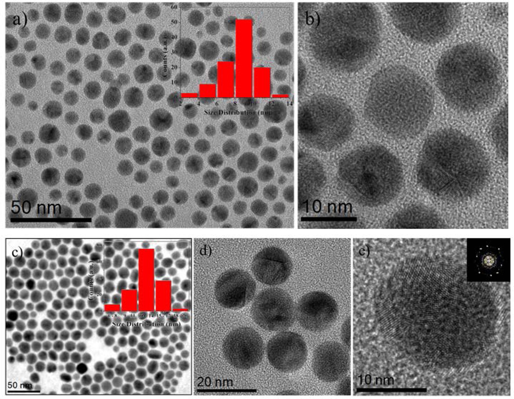
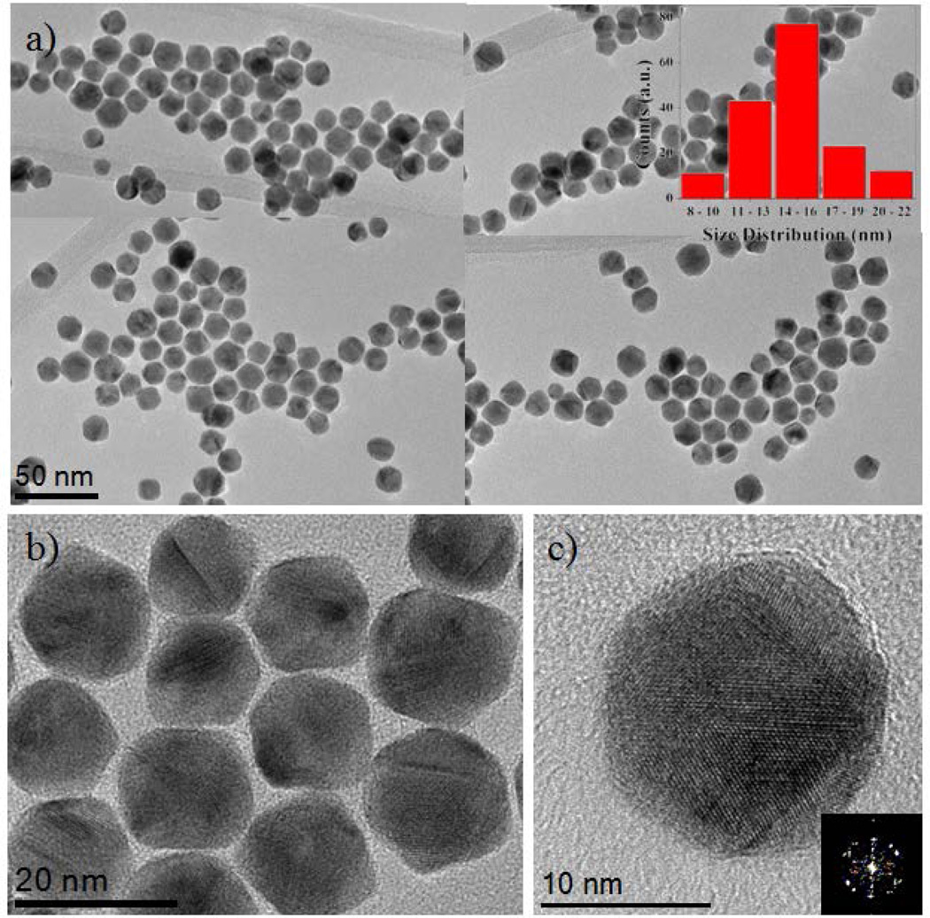
Monodispersed multiply twinned morphologies of AuCu/Pt trimetallic core-shell nanoparticles were synthesized in a one-pot synthesis method. First Au nanoparticles were synthesized at 110 °C by using oleylamine as solvent, reducing agent and stabilizer for the formation of nanoparticles as shown in Figure 1(a). The TEM image of Au nanoparticles has an average size range 9.0 ± 1.0 nm. (see histogram as inset). The TEM (HRTEM) micrographs illustrated the Au nanoparticles are multiply twinned morphologies (Figure 1(b)). Then, a copper acetate (CuCO2CH3) solution was immediately added to Au colloidal solution which was kept at 280 °C for 1 hour under the N2 ambient and resulted AuCu alloyed multiply twinned structure nanocrystals as shown in TEM micrographs of Figure 1(c). The average size of the AuCu nanoparticles is 13.0 ± 1.0 nm. (see inset histogram Figure 1(c)). Figure 1(e) corresponds to the HRTEM image of multiple twinned particles at five-fold and oriented along {112} zone axis. Next, in order to prepare the AuCu/Pt trimetallic core-shell structure nanoparticles, Pt precursors were added to the AuCu colloidal solution, which was kept at 240 °C for another 1 hour under the N2 atmosphere with magnetic stirring. The successive reduction of Pt resulted in the deposition of the Pt atoms on the surface of the AuCu alloy nanoparticles and formed AuCu/Pt TNPs. Figure 2(a) is a composed image made of low magnification TEM bright-field representative micrographs, showing these morphologies (also see Supporting Information (SI) Figure S1). The inset histogram from Figure 2(a) shows an average size (15.0 ± 1.0 nm) distribution of AuCu/Pt TNPs.
Figure 1.
(a) TEM image of the Au nanoparticles and inset histogram represents the size distribution of the particles (mean size range 9.0 ± 1.0 nm.), (b) HRTEM images of the multiply twinned structure Au nanoparticles, (c) Representative TEM image of AuCu nanoparticles, histogram shows an average size range (13.0 ± 1.0 nm.), (d) and (e) shows the HRTEM images of multiple twinned particles at the five-fold and oriented along {112} zone axis.
Figure 2.
(a) TEM image of AuCu/Pt trimetallic core-shell nanoparticles and the particle size ranging from 15.0 ± 1.0 nm. (b) and (c) HRTEM images of the multiple twinned structure nanoparticles which is oriented along the {001}zone axis.
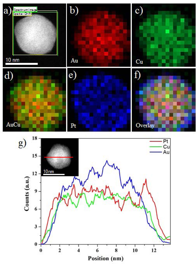
Figure 3(a) shows the HAADF-STEM image of AuCu/Pt trimetallic multiple twinned nanoparticles. The distributions of the Au, Cu and Pt in the nanoparticles were studied by the energy dispersive X-ray spectroscopy (EDS) techniques using the HAADF-STEM mode. The EDX techniques were applied to investigate the elemental mapping and cross-sectional compositional line profile of the nanostructures, which are two accepted characterizations showing the core-shell structures and elemental distributions of nanoparticles.35, 36 Here we observed the AuCu/Pt trimetallic multiple twinned particles are core-shell structure. The false colors red, green, and blue correspond to Au, Cu and Pt respectively. The Pt signal was readily observed and distributed in the surface of the AuCu alloyed nanostructures (Figure 3(e) and SI Figure S2); however, the Au and Cu signals were concentrated in the cores and formed AuCu alloyed nanostructures as shown in Figure 3(b–d). These converging color maps showed that the Pt atoms are overgrown on the surface of AuCu nano-alloys as shown in the overlay of the nanoparticles (Figure 3(f)). However, it must be noted that the Pt was deposited on the AuCu surface, instead of it appears to be conglomerated (see Figure 3(e)). Figure 3(g) shows a line-scan EDX spectrum of Au, Cu and Pt, recorded through the center of an individual nanoparticle (marked by a red line inset Figure 3(g)). The Pt signal was clearly traced across the entire particle (~12 nm), whereas the Au and Cu signals were obtained only across the core region (~9 nm). Therefore, the intensity profile shows the maximum intensity of the signals changing between the respective regions.
Figure 3.
(a) HAADF-STEM image of AuCu/Pt multiple twinned nanoparticles, (b–f) EDX elemental maps of nanoparticles – Au, Cu, AuCu alloy, Pt, and Overlay respectively, (g) Au, Cu and Pt elemental profiles along the red line across the particles (inset of g).
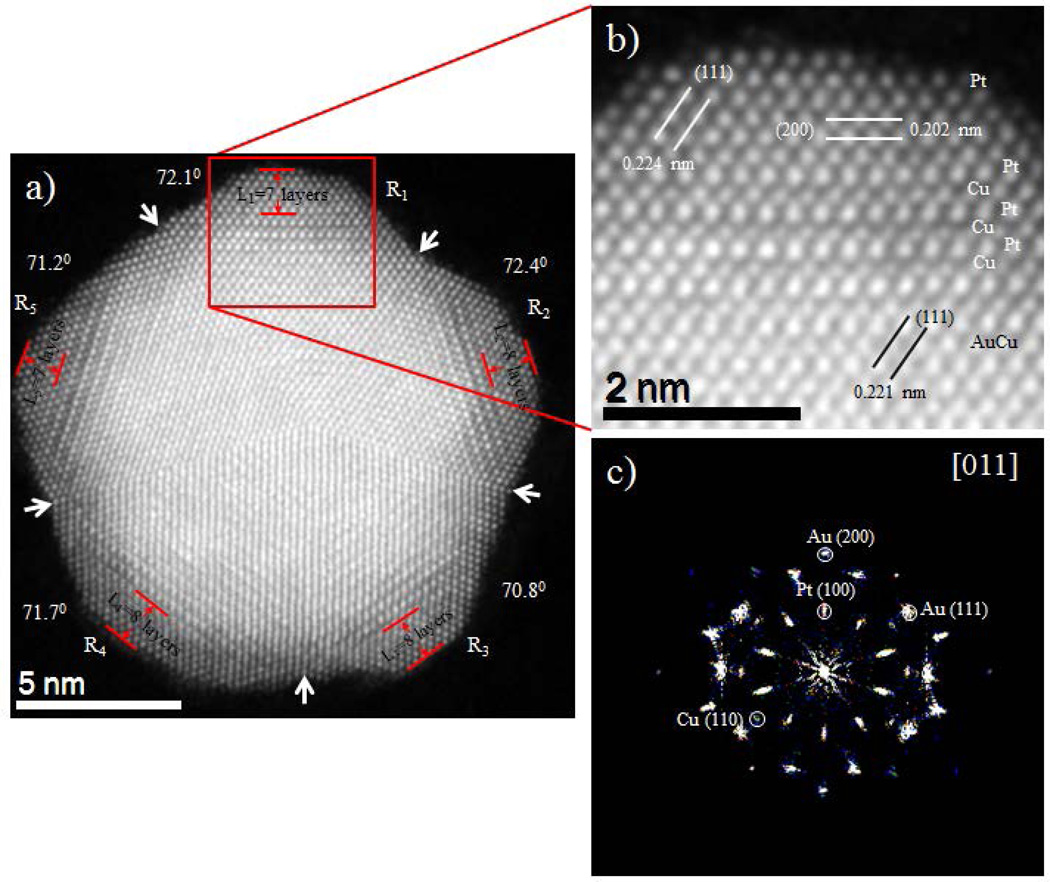
The atomic structures and component distributions of the AuCu/Pt trimetallic nanoparticles were observed using an aberration-corrected STEM equipped with HAADF detector. Figure 4 shows atomically resolved HAADF-STEM images for the AuCu/Pt penta-twin shaped nanoparticles. The brightness reflects the HAADF intensity signal depends not just on the amount of material but also on the elements present in the atomic column parallel to the electron beam,37 this technique is a very suitable choice for the analysis of the composition of the nanoparticles. The AuCu core is readily distinguishable in a multiple twinned shape as the Pt shell structure is that of a penta-twinned where it is possible to count the atomic layers of Pt. We measured all five facets of the Pt shell, L1 through L5, to be 7, 8, 8, 8 and 7 Pt layers respectively. Moreover, the twinning angles between (111) planes varied from 70.8° to 72.4° as presented in Figure 4, where the higher discrepancy (±1.6°) in region R2 and R3 is observed. The deviation of those values with the average angle 70.53° between {111} twin planes (for symmetrical monometallic decahedral nanocrystal) provides distortion and makes the particles strained. Figure 4(b) shows close-ups of the red square indicated by Figure 4(a) revealing that the composition of the individual columns can be corroborated by change in the intensity signal. In interface region, the diffusion of few layers of Cu on the Pt shell can be directly observed in the aberration corrected STEM micrograph. The intensity profile (SI Figure S3(d) marked by dot red arrow ‘X’) noted that the dramatic difference in the intensity due to the differences in atomic number. The average distance between Au-Au peaks is 0.236 nm, Pt-Cu peaks is 0.219 nm, and Pt-Pt peaks is 0.264 nm, these values are consistent with the Au {111}, CuPt {111} and Pt {110} planes respectively. The corresponding fast Fourier transforms (FFT) (Figure 4(c)) shows the main reflections conforming the particle oriented along [011] zone axis. In addition the core region of Figure 4(b) also exhibits the lattice spacing of 0.221 nm that agrees well with the inter lattice spacing of {111} lattice plane of AuCu alloy crystals. In addition, the shell region reveals that the lattice spacing of 0.224 nm and 0.202 nm, which are assigned with the inter lattice spacing of {111} and {200} planes of Pt crystals respectively. Furthermore, the intensity profile analysis of the top layer in SI Figure S3(b) marked by a red arrow ‘Y’ reveals the disparity of intensities between atomic columns indicating that there are incomplete atomic columns; therefore, they have to present kinks and adatoms in the outer layers (SI Figure S3(c)).
Figure 4.
(a) Atomic resolution HAADF-STEM image of a penta-twinned AuCu/Pt core-shell nanoparticle. Each tetrahedron (R1, R2, R3, R4, and R5) is identified by white arrow and the angles measured between the {111} twinning plane are 72.1°, 72.4°, 70.8°, 71.7°, and 71.2° as indicated. (b) Close-up of the image as indicated by the square showing the crystalline planes and different contrasts of Pt, Cu and Au lattices are readily observed, (c) Corresponding fast Fourier transform (FFT) shows the [011] zone axis.
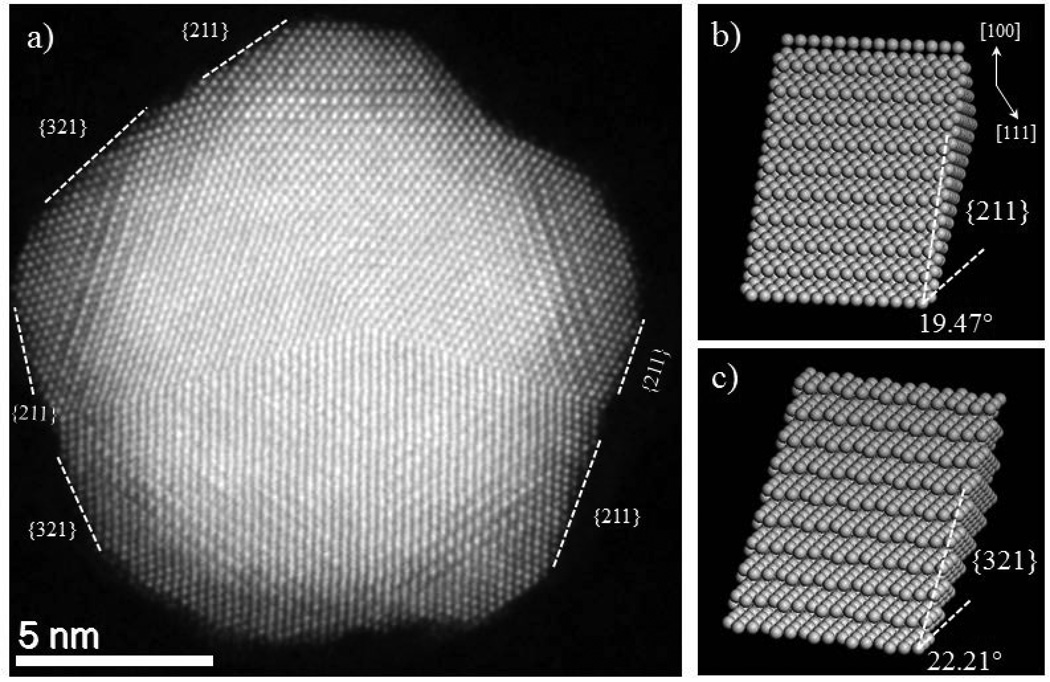
The close-up look from atomically resolved HAADF-STEM micrograph (Figure 5) shows that the surface of nanostructure is not flat and is composed of atoms with kinks, terraces and steps. The non-flat surfaces with the presence of high kinks and atomic step density, increases the reactivity of the nanostructure that will be suitable for both selective and reactive catalysis. Such surfaces are also called high index facets surfaces (HIFS). These kinks, adatoms and high-index facets are catalytically more active than low index surfaces,38 which further increases the premise of the potential use of these nanoparticles as catalysts. In some cases, there are only adatoms in the surface as represented by an arrow in SI Figure S3(b), while in most of the cases the surface presents HIFS as presented in the Figure 5(a). The average value of the miller indices for HIFS can be estimated by measuring the angle between the known plane (either (111) or (100)) and the high index surface. The average angles measured along different surfaces with respect to (111) plane corresponds to 20 degrees and with respect to (100) plane, corresponds to 34 degree, revealing the miller index family to be made from {211}. Another angles observed was 21.95 degree along (111) plane and 36 degree along (100) plane. The average value of this angle corresponds to HIFS with {321} family. From the nomenclature of the surface, {211} surface is made of {111} terraces and {100} step surface with 3 atoms in the row. The atomistic model for both {211} and {321} HIFS are presented in the Figure 5(b) and 5(c) respectively.
Figure 5.
(a) Shows HAADF image of 16 nm penta-twinned nanoparticles on a [011] zone axis with high index exposed facets, (b and c) Atomistic model for high-index facets {211} and {321} with steps and terraces.
4. Discussion
The multiply twinned particles (MTPs) consist of five (for decahedral) or twenty (for icosahedral) tetrahedral subunits, which are bounded together by (111) twinned planes. All facets of the decahedral or icosahedral particle are {111} planes, having the lowest surface free energy for a face centered cubic (fcc) metal. In terms of energy minimization, it is favorable to form decahedral or icosahedral MTPs thermodynamically in comparison with single crystal particles when the surface free energy of {111} is low.39 In our experiment we observed Au seeds and AuCu alloyed nanoparticles that are multiple twinned structures as shown in high resolution TEM micrograph Figure 1. Moreover, when the Pt precursor was added as a third metal, forming AuCu/Pt ternary penta-twinned structure, the structure exhibits both the diffuse interphase and epitaxial growth of the Pt shell on the AuCu alloy core. Among various parameters that affects the interdiffusion and epitaxial growth of core-shell nanostructures, the lattice mismatch between the core and shell metals has been shown to play a crucial role. Fan et al.40 reported the systematic investigation of the epitaxial growth of various novel metals, and concluded that the epitaxial growth of core-shell nanostructures is favored by small lattice mismatch (must be less than about 5 %), as well as electronegativity, atomic radius, bond dissociation energy
Here, we observed the epitaxial growth of Pt shell on top of the AuCu core because the lattice mismatch (1.3%) between Pt (0.3923 nm) and AuCu (0.3872 nm) below 5% is favorable for the epitaxial growth not only on the flat {111} facets but also on the sharp corners of multiple twinned particles where defects and distortion of tetrahedral units are accumulated.41 Besides the lattice mismatch, many other factors and the synergetic effects determine the growth mode. One could simply give the explanation in terms of the low surface free energy. Nonetheless, this is vague especially for the growth over nanocrystals in solution with complex components consisting of second or third metal ions, anions, and reducing and capping agents, which may alter the growth modes. According to the theory of nucleation and growth of heterogeneous structure of multimetallic nanoparticles, the growth mode is mainly determined by the lattice mismatch and interactions between the overlayer and substrate. Generally, there are three types of growth modes when a substance is deposited on a substrate in gas phase or vacuum, namely the Frank–van der Merwe (FM), Volmer–Weber (VW), and Stranski–Krastanov (SK) modes. These have been used to explain the formation of various nanostructures of alloy, and core-shell nanoparticles.42, 43 The three metals (Au, Cu, Pt) all share the fcc crystal structure; and the Pt shell could grow epitaxially on the AuCu core because of the latter’s smaller bulk lattice. Figure 4(a) shows the HAADF-STEM image of the FM and SK growth mode of the AuCu/Pt core-shell nanoparticles, where the condition of the FM growth mode depended on the smooth surface of as prepared AuCu MTPs, such as (111) facets. The directions of the overgrowth of atomic Pt monolayers on top of AuCu (111) facets were formed in layer-by-layer and island-on-wetting-layer, consequently, the small clusters and nanoclusters will gradually deposit on the surfaces of as-prepared cores in the epitaxial growth modes. Due to the presence of islands, the incomplete surface layers were formed and formation of high index facets as shown in Figure 5(a), where we observed {211} and {321} HIFS. High-index facets are highly open-structure surfaces, which have high density of atomic steps and kinks.44 These low coordinated atoms can easily interact with other molecules and preform as the active catalysts. Therefore, the catalytic activity of high-index facets is generally superior to that of low-index facets, which consist of densely packed atoms, for example {111} and {100}.32, 45
5. Conclusions
In summary, we successfully synthesized AuCu/Pt core-shell penta-twinned structure TNPs, consisting of a Pt monolayer shell and bimetallic AuCu core by one-pot colloidal synthesis method. The TEM micrographs elucidated the final morphologies of the Au and AuCu alloy seeds are multiply twinned structures and the final morphology of trimetallic structure resulted in penta-twinned shapes. Atomic resolution Cs-corrected STEM in combination with high resolution spectral and chemical analysis has been allowed us to see the Pt layers are overgrowth on the as prepared AuCu core by FM layer-by-layer and SK island-on-wetting-layer growth modes, the atomic structure of AuCu/Pt trimetallic nanoparticles and the chemical composition of different elements were found from the EDS analysis. The obtained nanostructure carries significant importance due to the highly reactive geometry obtained and observed by the atomic resolution microscopy. The presence of significant amount of copper in the structure was shown to make the nanostructures more cost effective and at the same time the presence of Pt atoms decorated surfaces with high index surfaces {321} and {211} makes them catalytically more active. In this paper we demonstrated the new way to control the nanoparticles morphologies by the presence of third metal (Pt). We believe that this work is a step closer to produce optimum catalysts in which the active phase forms only surface monolayers.
Supplementary Material
Acknowledgments
This work was supported by grants from the National Center for Research Resources (5 G12RR013646-12), and the National Institute on Minority Health and Health Disparities (G12MD007591) from the National Institutes of Health. The authors would like to acknowledge to the NSF for support with grants DMR-1103730, “Alloys at the Nanoscale: The Case of Nanoparticles Second Phase and PREM: NSF PREM Grant # DMR 0934218; “Oxide and Metal Nanoparticles-The Interface between Life Sciences and Physical Sciences”. In addition, the authors would like to acknowledge the support of the Welch Foundation (grant No. AX-1615, “Controlling the Shape and Particles Using Wet Chemistry Methods: The Case of Bimetallic Nanoparticles”.
Notes and References
- 1.Toshima N, Ito R, Matsushita T, Shiraishi Y. Catal. Today. 2007;122:239–244. [Google Scholar]
- 2.Tsai S-H, Liu Y-H, Wu P-L, Yeh C-S. J. Mater. Chem. 2003;13:978–980. [Google Scholar]
- 3.Toshima N. Macromol. Symp. 2008;270:27–39. [Google Scholar]
- 4.Khanal S, Casillas G, Velazquez-Salazar JJ, Ponce A, Jose-Yacaman M. J. Phys. Chem. C. 2012;116:23596–23602. doi: 10.1021/jp3092418. [DOI] [PMC free article] [PubMed] [Google Scholar]
- 5.Ding Y, Gao Y, Wang ZL, Tian N, Zhou Z-Y, Sun S-G. App. Phys. Lett. 2007;91 121901-121901-121903. [Google Scholar]
- 6.Tian N, Zhou Z-Y, Sun S-G, Ding Y, Wang ZL. Science. 2007;316:732–735. doi: 10.1126/science.1140484. [DOI] [PubMed] [Google Scholar]
- 7.Khanal S, Casillas G, Bhattarai N, Velázquez-Salazar JJ, Santiago U, Ponce A, Mejía-Rosales S, José-Yacamán M. Langmuir. 2013;29:9231–9239. doi: 10.1021/la401598e. [DOI] [PMC free article] [PubMed] [Google Scholar]
- 8.Bhattarai N, Casillas G, Khanal S, Bahena D, Velazquez-Salazar JJ, Mejia S, Ponce A, Dravid VP, Whetten RL, Mariscal MM, Jose-Yacaman M. MRS Commun. 2013:3,177–3,183. [Google Scholar]
- 9.Long NV, Yang Y, Minh Thi C, Minh NV, Cao Y, Nogami M. Nano Energ. 2013;2:636–676. [Google Scholar]
- 10.Bhattarai N, Khanal S, Bahena Uribe D, Olmos-Asar JA, Ponce A, Whetten R, Mariscal MM, Jose - Yacaman M. Phys. Chem. Chem. Phys. 2014 doi: 10.1039/c4cp01612b. [DOI] [PMC free article] [PubMed] [Google Scholar]
- 11.Golikand A, Lohrasbi E, Maragheh M, Asgari M. J. Appl. Electrochem. 2009;39:2421–2431. [Google Scholar]
- 12.Kadirgan F, Beyhan S, Atilan T. Int. J. Hydrogen Energ. 2009;34:4312–4320. [Google Scholar]
- 13.Koenigsmann C, Santulli AC, Gong K, Vukmirovic MB, Zhou W-p, Sutter E, Wong SS, Adzic RR. J. Am. Chem. Soc. 2011;133:9783–9795. doi: 10.1021/ja111130t. [DOI] [PubMed] [Google Scholar]
- 14.Lim B, Jiang M, Camargo PH, Cho EC, Tao J, Lu X, Zhu Y, Xia Y. Science. 2009;324:1302–1305. doi: 10.1126/science.1170377. [DOI] [PubMed] [Google Scholar]
- 15.Tedsree K, Li T, Jones S, Chan CWA, Yu KMK, Bagot PA, Marquis EA, Smith GD, Tsang SCE. Nat. nanotechnol. 2011;6:302–307. doi: 10.1038/nnano.2011.42. [DOI] [PubMed] [Google Scholar]
- 16.Yang J, Yang J, Ying JY. ACS Nano. 2012;6:9373–9382. doi: 10.1021/nn303298s. [DOI] [PubMed] [Google Scholar]
- 17.Fang P-P, Duan S, Lin X-D, Anema JR, Li J-F, Buriez O, Ding Y, Fan F-R, Wu D-Y, Ren B. Chem. Sci. 2011;2:531–539. [Google Scholar]
- 18.Steele BC, Heinzel A. Nature. 2001;414:345–352. doi: 10.1038/35104620. [DOI] [PubMed] [Google Scholar]
- 19.Service RF. Science. 2007;315:172. doi: 10.1126/science.315.5809.172. [DOI] [PubMed] [Google Scholar]
- 20.Long NV, Duy Hien T, Asaka T, Ohtaki M, Nogami M. Int. J. Hydrogen Energ. 2011;36:8478–8491. [Google Scholar]
- 21.Mani P, Srivastava R, Strasser P. J. Power Sources. 2011;196:666–673. [Google Scholar]
- 22.Wong CY, Chen S-K, Lo A-Y, Tseng C-M, Lin C-Y, Liu S-B. Int. J. Hydrogen Energ. 2013;38:12984–12990. [Google Scholar]
- 23.Kobayashi H, Yamauchi M, Kitagawa H, Kubota Y, Kato K, Takata M. J. Am. Chem. Soc. 2010;132:5576–5577. doi: 10.1021/ja1013163. [DOI] [PubMed] [Google Scholar]
- 24.Kobayashi H, Yamauchi M, Kitagawa H, Kubota Y, Kato K, Takata M. J. Am. Chem. Soc. 2008;130:1818–1819. doi: 10.1021/ja078126k. [DOI] [PubMed] [Google Scholar]
- 25.Wang L, Yamauchi Y. Chem. Mater. 2011;23:2457–2465. [Google Scholar]
- 26.Zhang H, Okumura M, Toshima N. J. Phys. Chem. C. 2011;115:14883–14891. [Google Scholar]
- 27.Khanal S, Bhattarai N, Velazquez-Salazar JJ, Bahena D, Soldano G, Ponce A, Mariscal MM, Mejia-Rosales S, Jose - Yacaman M. Nanoscale. 2013;5:12456–12463. doi: 10.1039/c3nr03831a. [DOI] [PMC free article] [PubMed] [Google Scholar]
- 28.Wang L, Yamauchi Y. J. Am. Chem. Soc. 2010;132:13636–13638. doi: 10.1021/ja105640p. [DOI] [PubMed] [Google Scholar]
- 29.Fang P-P, Duan S, Lin X-D, Anema JR, Li J-F, Buriez O, Ding Y, Fan F-R, Wu D-Y, Ren B, Wang ZL, Amatore C, Tian Z-Q. Chem. Sci. 2011;2:531–539. [Google Scholar]
- 30.Yang J, Chen X, Yang X, Ying JY. Energ. Environ. Sci. 2012;5:8976–8981. [Google Scholar]
- 31.Sun X, Li D, Ding Y, Zhu W, Guo S, Wang ZL, Sun S. J. Am.Chem. Soc. 2014;136:5745–5749. doi: 10.1021/ja500590n. [DOI] [PubMed] [Google Scholar]
- 32.Bhattarai N, Casillas G, Khanal S, Salazar JJ, Ponce A, Jose-Yacaman M. J. Nanopart. Res. 2013;15:1–13. [Google Scholar]
- 33.Wang R, Wang H, Wei B, Wang W, Lei Z. Int. J. Hydrogen Energ. 2010;35:10081–10086. [Google Scholar]
- 34.Accelrys Software Inc., San Diego. 2008 Release 4.4. [Google Scholar]
- 35.Ferrer D, Torres-Castro A, Gao X, Sepúlveda-Guzmán S, Ortiz-Méndez U, José-Yacamán M. Nano Lett. 2007;7:1701–1705. doi: 10.1021/nl070694a. [DOI] [PubMed] [Google Scholar]
- 36.Lim B, Wang J, Camargo PHC, Jiang M, Kim MJ, Xia Y. Nano Lett. 2008;8:2535–2540. doi: 10.1021/nl8016434. [DOI] [PubMed] [Google Scholar]
- 37.Pennycook S. Ultramicroscopy. 1989;30:58–69. [Google Scholar]
- 38.Barnard AS, Konishi H, Xu HF. Catal. Sci. Tec. 2011;1:1440–1448. [Google Scholar]
- 39.Marks L. Rep. Prog. Phys. 1994;57:603. [Google Scholar]
- 40.Fan FR, Liu DY, Wu YF, Duan S, Xie ZX, Jiang ZY, Tian ZQ. J. Am. Chem. Soc. 2008;130:6949–6951. doi: 10.1021/ja801566d. [DOI] [PubMed] [Google Scholar]
- 41.Tsuji M, Ikedo K, Matsunaga M, Uto K. Cryst. Eng. Comm. 2012;14:3411–3423. [Google Scholar]
- 42.Peng Z, Yang H. Nano Today. 2009;4:143–164. [Google Scholar]
- 43.Sau TK, Rogach AL. Adv. Mater. 2010;22:1781–1804. doi: 10.1002/adma.200901271. [DOI] [PubMed] [Google Scholar]
- 44.Lebedeva NP, Koper MTM, Feliu JM, van Santen RA. J. Phys. Chem. B. 2002;106:12938–12947. [Google Scholar]
- 45.Tian N, Zhou Z-Y, Yu N-F, Wang L-Y, Sun S-G. J. Am. Chem. Soc. 2010;132:7580–7581. doi: 10.1021/ja102177r. [DOI] [PubMed] [Google Scholar]
Associated Data
This section collects any data citations, data availability statements, or supplementary materials included in this article.


