Abstract
Robot-assisted surgical procedures, taking advantage of the high soft tissue contrast and real-time imaging of magnetic resonance imaging (MRI), are developing rapidly. However, it is crucial to maintain tactile force feedback in MRI-guided needle-based procedures. This paper presents a Fabry-Perot interference (FPI) based system of an MRI-compatible fiber optic sensor which has been integrated into a piezoelectrically actuated robot for prostate cancer biopsy and brachytherapy in 3T MRI scanner. The opto-electronic sensing system design was minimized to fit inside an MRI-compatible robot controller enclosure. A flexure mechanism was designed that integrates the FPI sensor fiber for measuring needle insertion force, and finite element analysis was performed for optimizing the correct force-deformation relationship. The compact, low-cost FPI sensing system was integrated into the robot and calibration was conducted. The root mean square (RMS) error of the calibration among the range of 0–10 Newton was 0.318 Newton comparing to the theoretical model which has been proven sufficient for robot control and teleoperation.
Keywords: Optical force sensor, Fabry-Perot interferometer, MRI compatible, Needle insertion
I. Introduction
MRI, whose high soft tissue contrast and real-time imaging could not be matched by other imaging modalities like CT or ultrasound, has been developing from primarily a diagnostic imaging approach to an interventional guidance tool in many clinical procedures. Several functional surgical robots and other devices operating in the MRI environment have been demonstrated recently, [1]–[4] just to name a few.
It is desired for needle-based interventions to have force feedback from the tip of the needle. Due to the consideration of MRI compatibility, most research on sensing were put on optical approaches. Fiber optic force sensors operate on non-electrical signals, thus are a promising technique for force sensing on a needle driver inside the MRI scanners bore.
As one of several optical approaches, Fiber Bragg Grating (FBG) sensors [5] have high sensitivity and miniaturization. It was demonstrated to measure the needle deflection inside MRI room by Park [6]. But the wavelength based method requires strict working condition and is of a much higher cost generated from specific optical source and spectral analysis equipments. In contrast, as an intensity and phase based measurement, Fabry-Perot interference fiber optic sensor is convenient to design and easy to manufacture [7]. With the miniature size and sterilizability, it becomes a excellent candidate for MRI compatible surgical sensors. In our previous research effort, we have developed a proof-of-concept prototype of the FPI fiber optic sensor system [8].
This paper introduces the optimized design of needle force sensor flexure followed by designing of a compact FPI interface for highly sensitive force sensing and finally the calibration of the whole FPI sensing system.
II. Principle of Fabry-Perot Interferometer
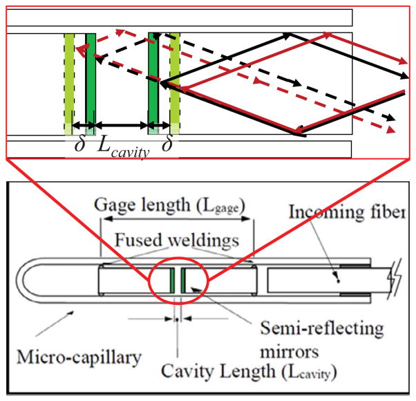
The main part of a Fabry-Perot strain sensor is a cavity which contains semi-reflective mirrors. Light is partially transmitted and partially reflected. The sensing gauge length is the distance between fused weldings and generally form the nanometer level distance between the two fiber tips. As shown in Fig. 1, Lcavity is the original cavity length when there is no force. 2δ is the change of the cavity length when a force is applied. Two red light paths shown in Fig. 1 interfere with each other creating black and white fringes which are different from the ones created by two black light paths. The detection of different fringe intensities will be resulted from the change of optical path length when cavity length is changed by the applied force.
Fig. 1.
FPI sensor element diagram(lower) and its sensing principle with light paths(upper).
The whole sensing method can be quantified through the summation of two waves [9]. At a given power for planar wave fronts, the reflected intensity equation could be written as below by multiplying the complex conjugate and applying Eulers identity.
| (1) |
where A1 and A2 are the amplitude coefficients of the reflected light. The equation 1 can be modified to represent only intensities by substituting and ϕ1 − ϕ2 = Δϕ as
| (2) |
III. Flexure design and opto-mechanical design for slave robot with FPI force sensing
To achieve force sensing within the required range for needle placement, firstly, a flexure mechanism design is presented. Secondly, designed from the previous study [10] which we have shown before, a compact and protable opto-mechanical system is presented. Comparing to the bulky prove-of-concept system, the new design is compact and could be easily integrated into the robot controller box inside the MRI room.
A. Flexure Design for Integration with Slave Robot
As mentioned previously, Fabry-Perot interference fiber optic sensor offers several advantages over other optical sensing methods. Firstly, in contrast to purely intensity modulated techniques, FPI, a combined intensity and phase modulated interferometry, provides absolute force measurement. It is independent of light source power variations – a common problem that occurs due to flexing of fiber optic cables. Secondly, taking advantage of multi-mode fiber, adverse effect of thermal and chemical changes could be minimized. Thirdly, the ability to be miniaturized in scale allows it to be integrated to surgical tools like catheters or needles. In addition to bio-compatibility, it is sterilization tolerant with ethylene oxide and autoclave. Most importantly, because it relies on simple interference pattern based voltage measurement, signal conditioning is simple in comparison with FBG sensors. The FPI fiber sensor (FOS-N-BA-C1-F1-M2-R1-ST, FISO Technologies, Inc., Canada) is relatively inexpensive (about $250) and can be designed to be disposable. Its operating temperature is −40° to 250°. The sensing strain ranges from ±1000με to ±5000με with resolution 0.01% of full scale.
The stain is calculated in the following formula:
| (3) |
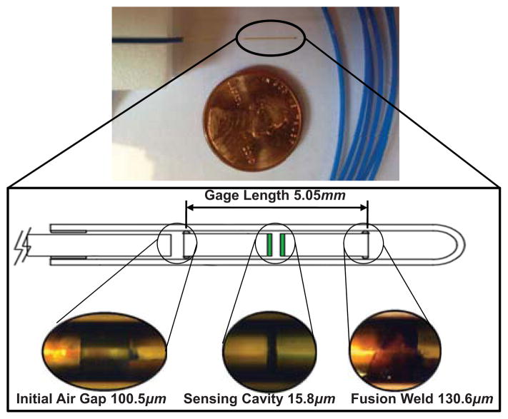
as shown in Fig. 2, Lcavity is the length of the Fabry-Perot sensing cavity, in nanometers (varies between 8, 000 and 23, 000nm), Lgage is the gage length (space between the fused weldings), in millimeters. Lo is the initial length of the Fabry-Perot cavity, in nanometers ε is the total strain measurement, in μ strain.
Fig. 2.
Actual FPI sensor element(upper) and a detailed view shown in inset(lower).
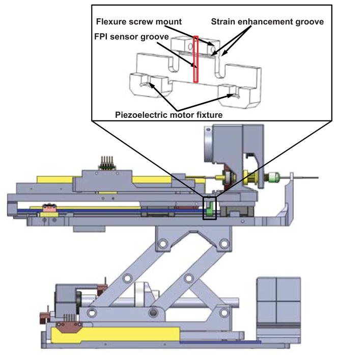
We have developed a 6 degree-of-freedom (DOF) MRI-compatible needle placement robot [11] which is shown in Fig. 3. It consists of 3-DOF needle driver module and a 3-DOF Cartesian stage with a fiducial tracking frame [12] integrated. The Cartesian stage consists of an insertion, a lateral and a vertical translation. The needle driver provides two co-axial insertion translations and an axial rotation. A preliminary study of this slave robot could be found in [8].
Fig. 3.
CAD model of FPI flexure integrated in the MRI-compatible needle placement robot.
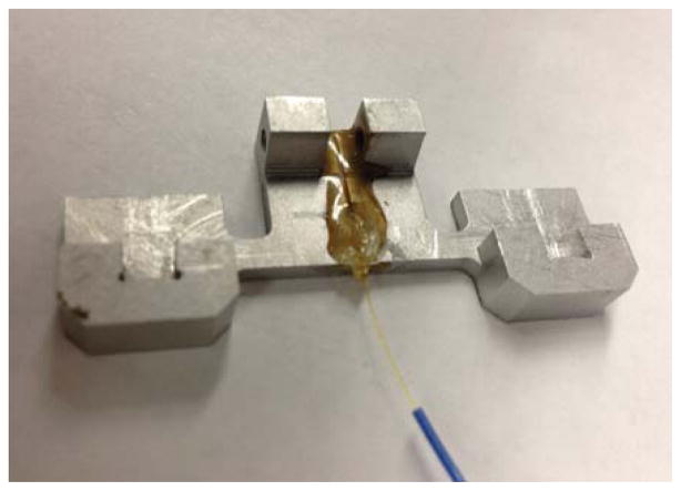
A flexure is designed to hold the FPI sensor and to be integrated with the prostate needle driver as shown in Fig. 3. The FPI fiber sensor is embedded inside the sensor groove vertically in Fig. 4. Two flexure screw mounts are used to couple with the robot mechanism. The length of sensing region is 10mm, and the center of active sensing region is 5mm away from the distal end of the fiber. Thus horizontal strain enhancement groove is located 5.75mm from the top of the flexure and 9.75mm from the bottom to allocate the full length of the fiber. The intersection of FPI sensor groove and strain enhancement groove is the center of active sensing region to maximize the sensing capability. The sensor installation involves a two-step procedure: After metal surface is well prepared by surface abrasion and neutralizer application, fiber cable is bonded by applying a very small drop (less than 1mm) of 5-minutes epoxy about 3mm away from the micro capillary and laying on adhesive slowly with a linear motion parallel to the gage orientation.
Fig. 4.
Actual flexure with FPI sensor attached.
Two piezoelectric motor fixture slots are used to constrain the piezoelectric motor drive rods, in combination with a quick disconnect fixture block. Aluminum alloy 6061 with Young’s Modulus of 69GPa is used as the material of the flexure. As shown in Fig. 5, finite element analysis (FEA) confirms that the design is capable of measuring 20 Newton needle insertion force. A strain enhancement groove, also developed through FEA, optimizes the flexure design, enhances the dynamic range and ensures that the strain is within the sensing range of FPI.
Fig. 5.
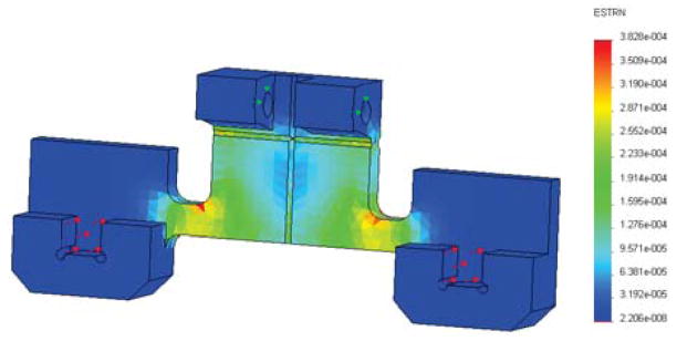
Finite element analysis result. Red arrows indicate the applied force, which is 10 Newton for each area, totally 20 Newton axial force. Green arrows indicate the fixed surface.
B. Compact and Portable Opto-mechanical Design
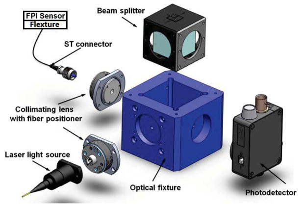
The preliminary benchtop opto-mechanical FPI interface system has been introduced in [10]. The dimension of the system is about 80cm × 80cm which is unacceptable for putting into our MRI-compatible robot controller box. To address this issue, we have designed a whole new system based on the same principle. The major innovation is the miniature optical fixture shown in Fig. 6. It consists of two collimators that connect laser source and FPI sensor with a photo detector on the third face and a beam splitter at center. This small fixture got the size of system shrunk from about 80cm × 80cm to about 10cm × 10cm thus it could be easily put into the controller box.
Fig. 6.
The optical fixture with two collimators, a photo detector and a beam splitter all together.
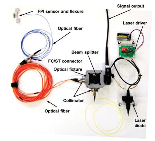
The final design is shown in Fig. 7. A laser driver (LD1100, Thorlabs, Inc., USA) provides constant power with continuous laser output adjustment. The light comes out of pigtailed laser diode (LPS-635-FC, Thorlabs, Inc., USA) and passes through the cube-mounted pellicle beam splitter (CM1-BP1, Thorlabs, Inc., USA). Two collimator (FiberPort PAF-X-2-532, Thorlabs, Inc., USA) are placed in orthogonal orientation inside an aluminum optical fixture. A 10 meter long optical fiber is connected to the FPI fiber cable through a FC/ST connector. The reflected light signal is detected by the photo detector and the voltage signal is sent to the control board. All of the optical system is enclosed inside the piezoelectric motor controller box with only one fiber coming out.
Fig. 7.
The compact opto-mechanical design of FPI interfaces that are capable of residing inside MRI robot controller box.
IV. FPI Sensor Calibration
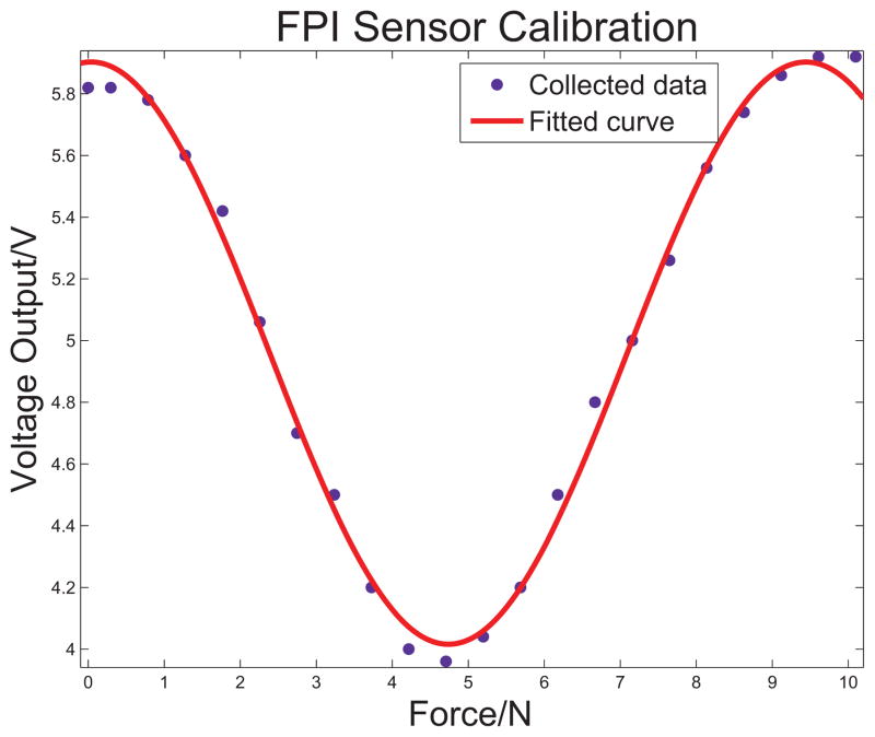
The calibration was conducted by adding standard weights on the FPI sensor flexure. The weights were put on a stage which has the same contact direction, positions and area as the real motor driving rods contact with the flexure, so that the measured force was in the same direction as the real needle force direction. The calibrated system can be seen in the voltage-force graph shown in Fig. 8. The dots shown in the figure represent the actual measurements. The calibrated curve was fitted to a sinusoidal function which is the theoretical relationship between the force and voltage. The output voltage follows this sinusoidal pattern that repeats over an increasing applied force. The relationship between force and final output voltage signal is
Fig. 8.
The sensor calibration result.
| (4) |
where f is the force in Newtons and u is the voltage in volts. The root mean square (RMS) error of the calibration is 0.318N.
V. DISCUSSION AND CONCLUSION
This paper presents a FPI based system of an MRI-compatible fiber optic sensor. A robot for prostate cancer biopsy and brachytherapy in 3T MRI scanner has been previously introduced and the FPI sensor was integrated into the robot with a flexure mechanism which was designed for working with FPI sensor together to measure needle insertion force. Finite element analysis was performed for optimizing its correct force-deformation relationship. To fit inside an MRI-compatible robot controller enclosure, the opto-electronic sensing system design was minimized. Finally, the compact, low-cost FPI sensing system was integrated into the robot system and calibration was conducted. The RMS error of the calibration among the range of 0–10 Newton was found to be 0.318 Newton comparing to the theoretical model which has proven sufficient for robot control and teleoperation.
Acknowledgments
This work is supported in part by the Congressionally Directed Medical Research Programs Prostate Cancer Research Program New Investigator Award W81XWH-09-1-0191 and NIH Bioengineering Research Partnership 1R01CA111288-01A1.
Contributor Information
Weijian Shang, Email: wshang@wpi.edu, Automation and Interventional Medicine (AIM) Robotics Laboratory, Department of Mechanical Engineering, Worcester Polytechnic Institute, 100 Institute Road, Worcester, MA 01609, USA.
Hao Su, Automation and Interventional Medicine (AIM) Robotics Laboratory, Department of Mechanical Engineering, Worcester Polytechnic Institute, 100 Institute Road, Worcester, MA 01609, USA.
Gang Li, Automation and Interventional Medicine (AIM) Robotics Laboratory, Department of Mechanical Engineering, Worcester Polytechnic Institute, 100 Institute Road, Worcester, MA 01609, USA.
Cosme Furlong, Center for Holographic Studies and Laser micromechaTronics (CHSLT) and NanoEngineering, Science and Technology (NEST), Department of Mechanical Engineering, Worcester Polytechnic Institute, 100 Institute Road, Worcester, MA 01609, USA.
Gregory S. Fischer, Email: gfischer@wpi.edu, Automation and Interventional Medicine (AIM) Robotics Laboratory, Department of Mechanical Engineering, Worcester Polytechnic Institute, 100 Institute Road, Worcester, MA 01609, USA.
References
- 1.Fischer GS, Iordachita II, Csoma C, Tokuda J, DiMaio SP, Tempany CM, Hata N, Fichtinger G. MRI-Compatible Pneumatic Robot for Transperineal Prostate Needle Placement. IEEE/ASME Transactions on Mechatronics. 2008;13(3) doi: 10.1109/TMECH.2008.924044. [DOI] [PMC free article] [PubMed] [Google Scholar]
- 2.Cole GA, Pilitsis JG, Fischer GS. Design of a Robotic System for MRI-Guided Deep Brain Stimulation Electrode Placement. IEEE Int Conf on Robotics and Automation; May 2009. [Google Scholar]
- 3.Martin AJ, Larson PS, Ostrem JL, Sootsman WK, Talke P, Weber OM, Levesque N, Myers J, Starr PA. Placement of deep brain stimulator electrodes using real-time high-field interventional magnetic resonance imaging. Magn Reson Med. 2005 Nov;54:1107–1114. doi: 10.1002/mrm.20675. [DOI] [PubMed] [Google Scholar]
- 4.Elhawary H, Tse ZTH, Hamed A, Rea M, Davies BL, Lamperth MU. The case for mr-compatible robotics: a review of the state of the art. The international journal of medical robotics and computer assisted surgery. 2008;4(2):105–113. doi: 10.1002/rcs.192. [DOI] [PubMed] [Google Scholar]
- 5.Park Y-L, Chau K, Black R, Cutkosky M. Force sensing robot fingers using embedded fiber bragg grating sensors and shape deposition manufacturing. Robotics and Automation, 2007 IEEE International Conference; 2007. pp. 1510–1516. [Google Scholar]
- 6.Park Y-L, Elayaperumal S, Ryu S, Daniel B, Black RJ, Moslehi B, Cutkosky M. MRI-compatible Haptics: Strain sensing for real-time estimation of three dimensional needle deflection in MRI environments,” in. International Society for Magnetic Resonance in Medicine (ISMRM), 17th Scientific Meeting and Exhibition; Honolulu, Hawaii. 2009. [Google Scholar]
- 7.Polygerinos P, Puangmali P, Schaeffter T, Razavi R, Seneviratne L, Althoefer K. Novel miniature MRI-compatible fiber-optic force sensor for cardiac catheterization procedures. Robotics and Automation (ICRA), 2010 IEEE International Conference; May 2010.pp. 2598–2603. [Google Scholar]
- 8.Su H, Zervas M, Cole G, Furlong C, Fischer GS. Real-time MRI-Guided Needle Placement Robot with Integrated Fiber Optic Force Sensing. IEEE ICRA 2011 International Conference on Robotics and Automation; Shanghai, China. 2011. [Google Scholar]
- 9.Gangopadhyay TK. Prospects for fibre bragg gratings and fabry-perot interferometers in fibre-optic vibration sensing. Sensors and Actuators A: Physical. 2004;113(1):20– 38. [Google Scholar]
- 10.Su H, Zervas M, Furlong C, Fischer G. A Miniature MRI-compatible Fiber-optic Force Sensor Utilizing Fabry-Perot Interferometer. SEM Annual Conference and Exposition on Experimental and Applied Mechanics; Uncasville, CT, USA. 2011. [Google Scholar]
- 11.Su H, Cardona D, Shang W, Camilo A, Cole G, Rucker D, Webster R, Fischer G. MRI-guided concentric tube continuum robot with piezoelectric actuation: A feasibility study. Robotics and Automation (ICRA), IEEE International Conference; 2012.pp. 1939–1945. [Google Scholar]
- 12.Shang W, Fischer GS. A High Accuracy Multi-Image Registration Method for Tracking MRI-Guided Robots. SPIE Medical Imaging (Image-Guided Procedures, Robotic Interventions, and Modeling Conference); San Diego, USA. 2012. [Google Scholar]


