Abstract
This paper presents a surgical master-slave tele-operation system for percutaneous interventional procedures under continuous magnetic resonance imaging (MRI) guidance. This system consists of a piezoelectrically actuated slave robot for needle placement with integrated fiber optic force sensor utilizing Fabry-Perot interferometry (FPI) sensing principle. The sensor flexure is optimized and embedded to the slave robot for measuring needle insertion force. A novel, compact opto-mechanical FPI sensor interface is integrated into an MRI robot control system. By leveraging the complementary features of pneumatic and piezoelectric actuation, a pneumatically actuated haptic master robot is also developed to render force associated with needle placement interventions to the clinician. An aluminum load cell is implemented and calibrated to close the impedance control loop of the master robot. A force-position control algorithm is developed to control the hybrid actuated system. Teleoperated needle insertion is demonstrated under live MR imaging, where the slave robot resides in the scanner bore and the user manipulates the master beside the patient outside the bore. Force and position tracking results of the master-slave robot are demonstrated to validate the tracking performance of the integrated system. It has a position tracking error of 0.318mm and sine wave force tracking error of 2.227N.
Keywords: MRI-compatible robot, percutaneous therapy, image-guided needle placement, pneumatic control, Fabry-Perot interferometry, haptics, teleoperation
I. Introduction
Mri has been evolving from primarily a diagnostic imaging modality to an interventional guidance tool in a number of clinical procedures, ranging from perfcutaneous intervention of prostates [1], endoscopic surgery of the abdomen [2] to cranial surgery [3]. In terms of the interaction between surgeon and robotic systems, surgical robots can be generally classified as three major categories [4], namely: supervisory controlled systems, teleoperated systems, and shared control systems. A teleoperation system is particularly favorable for MRI-guided therapy because it allows the clinician to directly control the procedure, while avoiding ergonomic issues associated with performing a procedure inside a scanner bore.
As it is clearly beneficial to visualize interventional procedures on the fly, but also commensurately challenging to develop MRI-compatible devices to assist surgeons, the past decade has witnessed significant endeavor from actualizing MRI-compatible instrumentations to elaborating intelligent surgical equipment utilizing robotics approaches [5], [6]. Since an open bore MRI scanner avails itself of more space for the surgeon and the medical equipment, either vertically (double-donut type, like SIGNA SP, 0.5 Tesla, General Electric, USA) [7] or horizontally (AIRIS-II, 0.3 Tesla, Hitachi Medical Corp., Japan) [8], early MRI-compatible robotics were tailored for procedures therein. However, the most commonly available MRI scanners are closed-bore, high field diagnostic MRI based on a single superconducting magnet. In addition to increased availability, this type of scanner can offer better image quality, resolution, and acquisition speeds; therefore, the goal of this work is to further enable interventional procedures in readily available high field MRI scanners.
This kind of MRI scanner bore imposes several challenges on MRI-guided needle placement procedures. First, needle placement is intrinsically difficult due to tissue deformation, edema, needle deflection, and respiration induced motion or involuntary motion of the patient, etc. Second, as the radiologist has to reach the surgical site inside scanner during the procedure, they have to mentally register the targets and surgical tool, which is time-consuming, awkward, and potentially unsafe and inaccurate. This often necessitates an iterative procedure where the patient is moved out of scanner for the intervention and move inside the scanner for imaging confirmation. Third, the limited space inside the bore is typically 60 – 70cm in diameter and 200cm in length. As the patient’s target anatomy is usually placed at the iso-center of the scanner and more than 1 meter away from the boundary of scanner, it was found that the ergonomics of manual needle placement or insertion proved very difficult in the confines of the scanner bore.
Teleoperation allows control of a needle insertion procedure from outside the scanner bore, but this removes the haptic feeback experienced by the surgeon which provides useful information as they place the needle. Correspondingly, we describe the following MRI-compatible master-slave teleoperation system with haptic feedback is desirable re-establish haptic sensation and address these issues. First, an MRI-compatible needle placement robot (slave robot) is designed with high accuracy to precisely control the needle motion. Second, a diverse array of sensors (e.g. position encoders, optical tool tracker) is integrated and fused to register and display the surgical tool information with the pre-operative or intra-operative MRI volume. Ultrasound-MRI registration or CT-MRI registration is also possible to be integrated to improve the surgical outcome. Third, the compact design of the robot is capable of circumventing the space limit to the surgeon. Most importantly, the teleoperated master-slave system described here allows the surgeon to perform the operation from beside the patient in the scanner room, but outside the constraints of the scanner bore, where the surgeon can control a haptic master device to teleoperate the slave robot to achieve simultaneous manipulation and visualization, and even dynamically compensate interventional errors. Since expert surgeons are known to rely on the kinesthetic feedback to identify tissue properties, a force feedback is crucial to the teleoperation system which usually sacrifices tactile feedback to achieve the aforementioned benefits.
Recently, a number of MRI-compatible manipulators have been developed to serve as the slave robot from a teleoperation perspective, [9]–[13] to name only a few. For a detailed review of current status, see [14], [15] for details. Currently, the field of MRI-compatible haptic devices is also quickly sprouting. Gassert et al. [16] employed a haptic interface with light intensity based fiber optic sensor to measures interaction forces with the human subject for a neuroscience brain activity study with functional MRI (fMRI). Yu et al. [17] compared hydrodynamic and pneumatic actuation of haptic interfaces during live fMRI. Hara et al. [18] investigated an electrostatic haptic joystick for similar applications. Turk-seven and Ueda [19] designed and evaluated a 1-axis force sensing haptic interface utilizing light intensity modulation.
MRI-compatible master-slave system developments have been carried out in very few groups. Kokes et al. [20] evaluated a teleoperated hydraulic needle driver robot utilizing commercially available haptic interface (PHANTOM Omni, SensAble Technologies, Inc, USA) which is not MRI-compatible, thus located outside the MRI room. Yang et al. [21] from the same group developed a pneumatic needle driver with piezoelectric driven Cartesian stage (slave robot) and a master robot with electrical motor actuation and commercially available force sensor. Seifabadi et al. [22]–[24] evaluated position tracking accuracy for a teleoperated needle insertion robot without haptic feedback. Tse et al. [25] developed a haptic system with piezoelectric motor and proposed neural network based admittance force control.
In our previous research effort, we have developed piezoelectric actuator drivers to control prostate needle placement robot [26] and concentric tube robot [27] allowing simultaneous imaging with robot motion. From meticulous analysis and comparison of different actuation and sensing principles, piezoelectric actuation is preferable to pneumatic or hydraulic approaches in applications such as needle placement due to its high position control accuracy. Pneumatic systems, which can use direct regulation of air pressure, are intrinsically ideal for force control, thus a favorable candidate for human-robot haptic interaction. Fiber optic force sensors operate on non-electrical signals, thus the promising technique for force sensing on a needle driver inside the MRI scanner’s bore. However, stain gage based force sensor [28] can be designed to work outside MRI scanner bore, such as in a master manipulator.
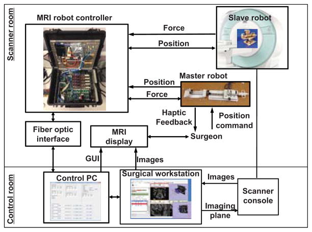
As shown in Fig. 1, the teleoperation system and the surgeon are located inside MRI scanner room. The procedure can be monitored from the scanner console as redundant safety mechanism. The interventional slave robot is located inside the scanner bore to perform the procedure under teleoperation from the haptic master robot which is also inside the scanner room besides the patient bed. The surgeon manipulates the haptic device to control needle placement, whereas the FPI fiber optic force sensor measures needle insertion force and reflects back to the surgeon by the pneumatic haptic device. The force controller regulates surgeon’s force sensation by closing an impedance control force feedback loop with a master side strain gauge force sensor.
Fig. 1.
System architecture for the master-slave teleoperation system where the haptic master device provides force feedback while MRI display provides visual feedback during intervention.
The primary contributions of this paper include: 1) optimizing the design of needle force sensor flexure and designing a compact FPI interface for highly sensitive force sensing; 2) developing a pneumatic haptic master device with strain gauge force sensing for human-in-the-loop interaction, 3) integrating a master device with previously designed piezoelectrically actuated prostate needle placement robot to implement an MRI-compatible hybrid actuated teleoperation system inside MRI scanner room; 4) implementing a bilateral teleoperation control of the master-slave system; 5) experimentally evaluating position and force tracking of the master-slave robotic system.
II. Flexure design and opto-mechanical design for slave robot with FPI force sensing
We have developed a 6 degree-of-freedom (DOF) needle placement robot which consists of 3-DOF needle driver module and a 3-DOF Cartesian stage with a fiducial tracking frame [29]. The Cartesian stage consists of an insertion, a lateral and a vertical translation. The needle driver provides two co-axial insertion translations and an axial rotation. A preliminary study of this slave robot is shown in [26].
To achieve force sensing within the required range for needle placement, a flexure mechanism design is presented here. The early study [30] shows that the original opto-mechanical design is bulky and difficult to be integrated inside MRI scanner room with the piezoelectric motion control system. The developed more compact and portable opto-mechanical laser driver and interrogator is imperative for MRI applications.
A. Flexure Design for Integration with Slave Robot
Besides fiber optic sensors utilizing light intensity modulation (e.g. [31]), wavelength modulation approach is also studied by Park et al. using Fiber Bragg grating (FBG) [32]. However, Fabry-Perot interference fiber optic sensor offers several advantages over other approaches. First, in contrast to intensity modulated techniques, FPI, a phase modulated interferometry, provides absolute force measurement, independent of light source power variations – a common problem that occurs due to flexing of fiber optic cables. Second, it takes advantage of multi-mode fiber and minimizes adverse effect of thermal and chemical changes. Third, it can be miniaturized in meso-scale and integrated to surgical tools (e.g. catheters or needles). In addition to bio-compatibility, it is sterilization tolerant with ethylene oxide and autoclave. The operating temperature is −40° to 250°. The sensing strain ranges from ±1000με to ±5000μ ε with resolution 0.01% of full scale. Most importantly, because it relies on simple interference pattern based voltage measurement, signal conditioning is simple in comparison with FBG sensors. The FPI fiber sensor element (FISO Technologies, Inc., Canada) is relatively inexpensive (about $250) and can be designed to be disposable. The strain measurement principle with the annotation of length of the cavity and gauge (modified based on datasheet from the vendor) is shown in Fig.2.
Fig. 2.
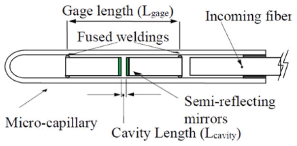
FPI sensor element showing the strain measurement optical components [33].
The stain is calculated in the following formula:
where Lcavity is the length of the Fabry-Perot cavity, in nanometers (varies between 8, 000 and 23, 000nm), Lgage is the gauge length (space between the fused weldings), in millimeters. Lo is the initial length of the Fabry-Perot cavity, in nanometers ε is the total strain measurement, in μ trains.
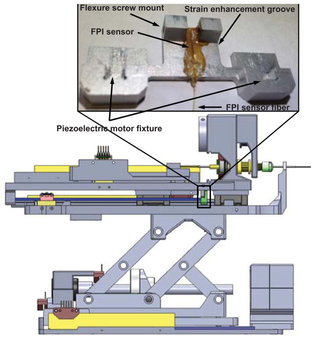
The FPI fiber sensor (FOS-N-BA-C1-F1-M2-R1-ST, FISO Technologies, Inc., Canada) is embedded inside the sensor groove vertically and the flexure is integrated with the prostate needle driver as shown in Fig.3. Two flexure screw mounts are used to couple with the robot mechanism. A strain enhancement groove, developed through finite element analysis (FEA) optimization of the flexture design, enhances the dynamic range and ensures that the strain is within the sensing range of FPI. The length of sensing region is 10mm, and the center of active sensing region is 5mm away from the distal end of the fiber. Thus horizontal strain enhancement groove is located 5.75mm from the top of the flexure and 9.75mm from the bottom to allocate the full length of the fiber. Two piezoelectric motor fixture slots are used to constrain the piezoelectric motor drive rods, in combination with a quick disconnect fixture block.
Fig. 3.
Flexure configuration integrated with the slave prostate needle placement manipulator. The inlay shows the flexure design and FPI fiber sensor element embedded inside the sensor groove. The FPI sensor element is placed vertically on the surface of the flexure.
Aluminum alloy 6061 with Young’s Modulus of 69GPa is used as the material of the flexure. As shown in Fig.4, FEA confirms that the design is capable of measuring 20 Newton needle insertion force. The calibration is conducted by adding standard weights on the FPI sensor flexure in the same direction as the real needle force direction. The calibrated relationship between force and final output voltage signal is
Fig. 4.
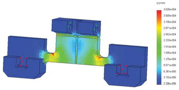
Finite element analysis result. Red arrows indicate the applied force, which is 10 Newton for each area, totally 20 Newton axial force. Green arrows indicate the fixed surface.
where f is the force in Newtons and u is the voltage in volts. The root mean square (RMS) error of the calibration is 0.318N.
B. Compact and Portable Opto-mechanical Design
The dimension of the preliminary benchtop opto-mechanical FPI interface system is about 80cm ×80cm to generate the light pathway. To reduce cost and size, a compact design iteration is developed to replace the typical benchtop FPI interfaces with a portable device that can reside inside the MRI robot controller box as described in the preliminary study [30] The final design is shown in Fig.5. A laser driver (LD1100, Thorlabs, Inc., USA) provides constant power with continuous laser output adjustment using a pin-programmable feedback gain. The light passes through pigtailed laser diode (LPS-635-FC, Thorlabs, Inc., USA) and goes through the cube-mounted pellicle beam splitter (CM1-BP1, Thorlabs, Inc., USA). Two collimator (FiberPort PAF-X-2-532, Thorlabs, Inc., USA) are placed in orthogonal orientation inside an aluminum optical housing. A 10 meter long optical fiber is connected to the FPI fiber cable through a FC/ST connector. All of the optical system is enclosed inside the piezoelectric motor controller located in the scanner room.
Fig. 5.
The compact opto-mechanical design of FPI interfaces that are capable of residing inside MRI robot controller box.
III. Pneumatic driven master robot with strain gauge force sensing
The search for actuation approaches for haptic device with force feedback has been arduous since it requires to be MRI-compatible, reliable, and robust. Piezoelectric motors have been evaluated in our research group, as well as in [25], [34] with admittance control to regulate force outputs or novel mechanism design [35] as haptic actuators. However, our experience shows that this kind of motor is inherently non-backdrivable and relies on friction interaction between piezoelectric elements and the motor drive rod or ring, and therefore suffers from quickly wearing out and failure in a short operation duration [36]. Pneumatic actuation has been used for MRI-compatible master robots, since it can be designed without ferrous components or electrical signals and more importantly, the pressure output has a direct relationship with control signal which makes the force control much easier than piezoelectric motors. Thus pressure regulated pneumatics becomes a natural choice as an actuator for a haptic master device. To our knowledge, this is the first development for MRI-guided surgical applications by utilizing hybrid pneumatic-piezoelectric actuation for master-slave control, respectively.
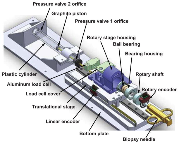
As shown in Fig. 6, the haptic master device includes a rotation encoded module to sense the rotation motion of the virtual needle’s handle for steering, and also a translational module that provides pneumatically actuated haptic force feedback. A key feature of this design is that it decouples the rotation and translation motion. The bearing housing follows the rotation of the shaft actuated by user manual rotation of the biopsy needle. Then the outer ring of the ball bearings is rotated correspondingly. The inner ring of the ball bearing maintains not rotated, but transmits the insertion force exerted by the translation module. The two angular contact ball bearings (Igus, Inc., East Providence, RI, USA) are placed against each other to provide better support to axial direction force.
Fig. 6.
CAD model of the pneumatic haptic master device with decoupled rotation and translation mechanisms. An aluminum load cell is calibrated to measure interaction force between the user and the biopsy needle. A custom MRI-compatible pneumatic cylinder is used to render force. The mechanism includes a rotation, translation, and the haptic module that provides pneumatically actuated haptic force feedback.
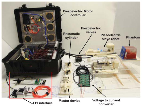
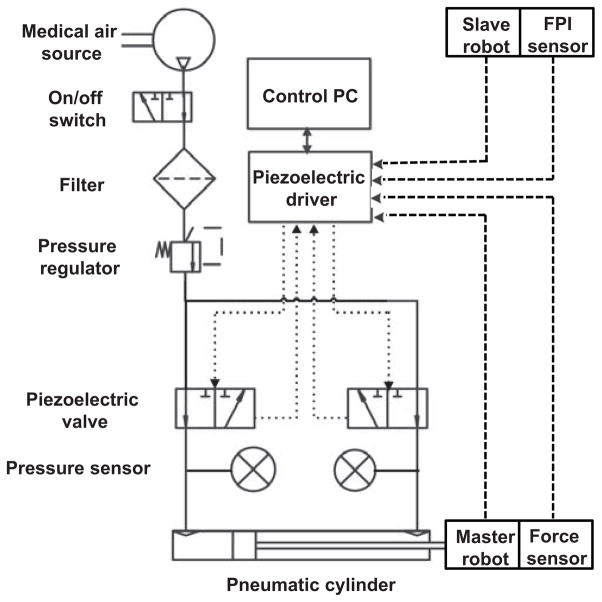
Fig. 6 depicts the CAD model of the pneumatic haptic master device while Fig. 7 illustrates the system schematic. A custom MRI-compatible pneumatic cylinder [37], which is regulated by an opposing pair of high speed piezoelectric pressure regulator valves (PRE-I, Hoerbiger, Germany), is used to render force. With a fast response time of 10ms and a relationship between pressure and control current by 2mA/bar (1bar is 100, 000 Pa), this MRI-compatible piezoelectric valve can regulate pressure up to 689kPa with control input ranging from 0 to 20mA. A linear voltage to current conversion circuit board is designed to transmit the 0 – 48V analog output from the piezoelectric motor controller [27] to the desired current. Two pressure sensors (PX309-100G5V, Omega, USA) are used to measure the pressure output of the valves. All of the valves, circuit board and pressure sensors are enclosed inside the controller box located in the scanner room to eliminate the distance between the valves and pneumatic cylinders as much as possible in order to reduce the cylinder response time. An aluminum load cell (MLP-10, Transducer Techniques, USA) with 44.45 Newton sensing range is also used to measure interaction force between the user and the biopsy needle.
Fig. 7.
Mechanical and electrical connection of the master-slave system, where solid line shows the mechanical connection, dashed and dotted line shows the electrical signal. The MRI robot controller supports analog input/output for force sensing and piezoelectric valve control in addition to piezoelectric motor actuation.
IV. Experimental Evaluation of Integration and Control of Master-Slave Teleoperation System
The master-slave system integration and evaluation of the position and force tracking capability of the bilateral teleoperation system is described in this section. Teleoperated needle placement results under continuous live MRI guidance are also reported.
A. Slave Robot Position Tracking Experiment
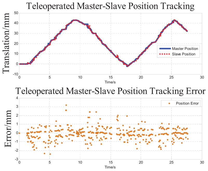
The accuracy study starts from a position tracking experiment of the slave robot to follow master robot motion. The master robot is manually moved in the insertion direction to simulate an approximated sinusoidal motion. Both master and slave positions are recorded while running teleoperation by sending master robot position to slave robot in a servo loop running at 1kHz. As shown in Fig. 8, the slave robot’s insertion axis tracks the master robot motion in a range about 43mm. The RMS error of position tracking is 0.318mm. The fastest tracking speed during the test is 4.76mm/s, which is sufficient for manual needle insertion procedures.
Fig. 8.
Master-slave position tracking results and its error. The master robot is manually moved and the insertion axis of slave robot tracks this motion in 27.6 seconds with 0.318 mm RMS error.
B. Master Robot Force Tracking Experiment
The master robot force tracking was further evaluated in a benchtop setting. The master robot is pushed against a rigid fixture to maintain solid stabilization of the biopsy needle interface. Then master robot is commanded to track the force from a simulated FPI sensing of slave robot. The pressure force generated by the opposing pair of piezoelectric valves is
where P1 and P2 are pressure of the two chambers, A1 and A2 are the piston areas. For the desired control force Fd, the desired pressure of each valve is calculated as follows:
If Fd < 0,
where P10 and P20 are initially set pressure of the two chambers.
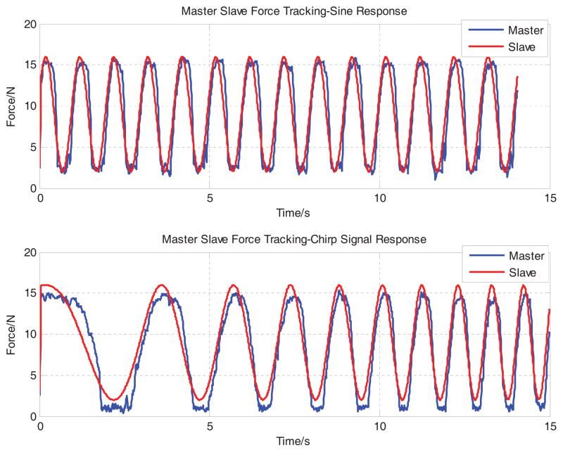
For the purpose of evaluation, both sinusoidal (constant frequency) and chirp (time varying frequency) voltage signals are used as simulated FPI reference forces. The reference sinusoidal force signal is defined as F d = a sin(2πft)+ b, where a = 7, b = 9, f = 1. The reference chirp force signal is defined as F d = a sin(2πft) + b, where a = 7, b = 9, f = 0.01t. Fig. 9 demonstrates that the tracking capability of the two signals with RMS errors 2.227N and 2.580 N respectively. As this preliminary result tracks 1Hz sinusoidal force signal, whereas the one from [17] is much slower at 0.1 Hz with a similar tracking performance.
Fig. 9.
Master-slave force tracking results. The master robot is regulated to track a 1Hz sinusoidal (top) and chirp signal (bottom) to evaluate the bandwidth the force control system. RMS errors are 2.227 Newton and 2.580 Newton respectively.
C. Teleoperated Needle Insertion under Live MRI
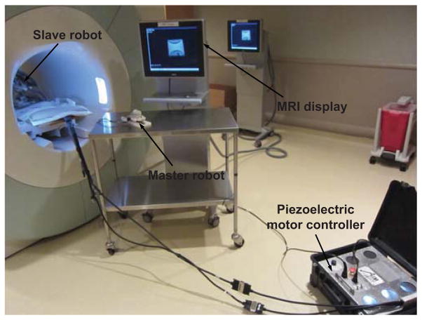
Fig. 10 illustrates the teleoperation system setup with a Siemens 3 Tesla MRI scanner. A clinical MRI-compatible display resides beside the scanner to provide visual feedback of live imaging during the teleoperated needle placement procedure.
Fig. 10.
MRI-compatible teleoperation system setup with a Siemens 3 Tesla MRI scanner. A clinical MRI display resides besides the scanner to visualize the teleoperated needle placement procedure.
A clinical 18 gauge biopsy needle (Invivo International, Netherlands) which is made of low artifact titanium is used for insertion into gelatin phantom. Fig. 11 shows four example screen shots of the needle trajectory from insertion to retraction under live MRI guidance. The imaging sequences utilized echo planar imaging (EPI) at 2Hz to visualize the real-time insertion. Needle artifact at the tip is observed. The crescent shaped artifact is largely due the imaging sequence itself. We have thoroughly demonstrated the capability of our system to operate during live imaging without visually observable artifact [26], and are working to evaluate the optimal real-time scan parameters for monitoring needle insertion.
Fig. 11.
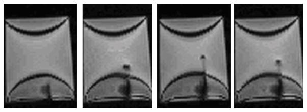
Example screen shots of the needle trajectory from insertion to retraction under live MRI guidance during teleoperation. The 18 gauge clinical needle made of titanium induces visually identifiable artifact for tracking with an echo planar imaging sequence at 2Hz.
V. DISCUSSION AND CONCLUSION
This paper presents a surgical master-slave teleoperation system for percutaneous interventional procedures under continuous MRI guidance. Prostate biopsy is the primary clinical application, while this system is generally applicable for other percutaneous procedures (e.g. neurosurgery or cardiac interventions). By leveraging the complementary feature of two MRI-compatible actuation approaches, a pneumatically actuated haptic master robot is developed to render needle placement force with a piezoelectrically actuated slave robot with FPI force sensing. Force and position tracking results are demonstrated to validate the tracking performance of the integrated system.
Teleoperated prostate biopsy for multiple targets has been conducted in the hospital, and a thorough analysis of the accuracy of this result is under way. Improved imaging sequence development is in progress. An advanced force control algorithm is being exploited to improve the force tracking performance. Statistical user study would facilitate to understand the system performance in comparison with manual needle placement.
Acknowledgments
This work is supported in part by the Congressionally Directed Medical Research Programs Prostate Cancer Research Program New Investigator Award W81XWH-09-1-0191, NIH Bioengineering Research Partnership 1R01CA111288-01A1, and Link Foundation Fellowship in Advanced Simulation and Training.
Contributor Information
Weijian Shang, Email: wshang@wpi.edu.
Gregory S. Fischer, Email: gfischer@wpi.edu.
References
- 1.Yakar D, Schouten MG, Bosboom DGH, Barentsz JO, Scheenen TWJ, Ftterer JJ. Feasibility of a pneumatically actuated mr-compatible robot for transrectal prostate biopsy guidance. Radiology. 2011;260(1):241–247. doi: 10.1148/radiol.11101106. [DOI] [PubMed] [Google Scholar]
- 2.Vogl TJ, Straub R, Eichler K, Woitaschek D, Mack MG. Malignant Liver Tumors Treated with MR Imaging Guided Laser-induced Thermotherapy: Experience with Complications in 899 Patients. Radiology. 2002;225(2):367–377. doi: 10.1148/radiol.2252011171. [DOI] [PubMed] [Google Scholar]
- 3.Schulder M, Liang D, Carmel PW. Cranial surgery navigation aided by a compact intraoperative magnetic resonance imager. Journal of Neurosurgery. 2001;94(6):936–945. doi: 10.3171/jns.2001.94.6.0936. [DOI] [PubMed] [Google Scholar]
- 4.Nathoo N, Çavusoglu M, Vogelbaum M, Barnett G. In touch with robotics: neurosurgery for the future. Neurosurgery. 2005;56(3):421. doi: 10.1227/01.neu.0000153929.68024.cf. [DOI] [PubMed] [Google Scholar]
- 5.Jolesz FA, Morrison PR, Koran SJ, Kelley RJ, Hushek SG, Newman RW, Fried MP, Melzer A, Seibel RMM, Jalahej H. Compatible instrumentation for intraoperative MRI: Expanding resources. Journal of Magnetic Resonance Imaging. 1998;8(1):8–11. doi: 10.1002/jmri.1880080105. [DOI] [PubMed] [Google Scholar]
- 6.Gassert R, Burdet E, Chinzei K. Opportunities and challenges in mr-compatible robotics. Engineering in Medicine and Biology Magazine, IEEE. 2008;27(3):15–22. doi: 10.1109/EMB.2007.910265. [DOI] [PubMed] [Google Scholar]
- 7.Chinzei K, Miller K. Towards MRI guided surgical manipulator. Med Sci Monit. 2001;7(1):153–163. [PubMed] [Google Scholar]
- 8.Koseki Y, Washio T, Chinzei K, Iseki H. Manipulator for Transnasal Neurosurgery, Optimized for and Compatible to Vertical Field Open MRI. In: Dohi T, Kikinis R, editors. Medical Image Computing and Computer-Assisted Intervention ?MICCAI 2002. Springer; Berlin/Heidelberg: 2002. pp. 114–121. 2488 of Lecture Notes in Computer Science. [Google Scholar]
- 9.Stoianovici D, Song D, Petrisor D, Ursu D, Mazilu D, Muntener M, Mutener M, Schar M, Patriciu A. MRI Stealth robot for prostate interventions. Minim Invasive Ther Allied Technol. 2007;16(4):241–248. doi: 10.1080/13645700701520735. [DOI] [PMC free article] [PubMed] [Google Scholar]
- 10.Vartholomeos P, Qin L, Dupont PE. MRI-powered actuators for robotic interventions. Intelligent Robots and Systems (IROS), 2011 IEEE/RSJ International Conference; 2011; pp. 4508–4515. [DOI] [PMC free article] [PubMed] [Google Scholar]
- 11.Song S-E, Cho N, Fischer GS, Hata N, Tempany C, Fichtinger G, Iordachita I. Development of a pneumatic robot for MRI-guided transperineal prostate biopsy and brachytherapy: New approaches. Robotics and Automation (ICRA), 2010 IEEE International Conference; may 2010; pp. 2580–2585. [DOI] [PMC free article] [PubMed] [Google Scholar]
- 12.Li M, Kapoor A, Mazilu D, Horvath K. Pneumatic Actuated Robotic Assistant System for Aortic Valve Replacement Under MRI Guidance. Biomedical Engineering, IEEE Transactions on. 2011 Feb;58:443–451. doi: 10.1109/TBME.2010.2089983. [DOI] [PubMed] [Google Scholar]
- 13.Yang B, Tan UX, McMillan A, Gullapalli R, Desai J. Design and Control of a 1-DOF MRI-Compatible Pneumatically Actuated Robot With Long Transmission Lines. Mechatronics, IEEE/ASME Transactions on. 2011;16(6):1040–1048. doi: 10.1109/TMECH.2010.2071393. [DOI] [PMC free article] [PubMed] [Google Scholar]
- 14.Tsekos N, Khanicheh A, Christoforou E, Mavroidis C. Magnetic resonance-compatible robotic and mechatronics systems for image-guided interventions and rehabilitation: a review study. Annu Rev Biomed Eng. 2007;9:351–387. doi: 10.1146/annurev.bioeng.9.121806.160642. [DOI] [PubMed] [Google Scholar]
- 15.Elhawary H, Zivanovic A, Rea M, Davies B, Besant C, McRobbie D, de Souza N, Young I, Lampth M. The feasibility of MR-image guided prostate biopsy using piezoceramic motors inside or near to the magnet isocentre. Med Image Comput Comput Assist Interv Int Conf Med Image Comput Comput Assist Interv. 2006;9(Pt 1):519–526. doi: 10.1007/11866565_64. [DOI] [PubMed] [Google Scholar]
- 16.Gassert R, Moser R, Burdet E, Bleuler H. MRI/fMRI-compatible robotic system with force feedback for interaction with human motion. Mechatronics, IEEE/ASME Transactions on. 2006 Apr;11:216–224. [Google Scholar]
- 17.Yu N, Hollnagel C, Blickenstorfer A, Kollias S, Riener R. Comparison of MRI-Compatible Mechatronic Systems With Hydrodynamic and Pneumatic Actuation. Mechatronics, IEEE/ASME Transactions on. 2008 Jun;13:268–277. [Google Scholar]
- 18.Hara M, Matthey G, Yamamoto A, Chapuis D, Gassert R, Bleuler H, Higuchi T. Development of a 2-DOF electrostatic haptic joystick for MRI/fMRI applications. Robotics and Automation, IEEE International Conference; may 2009.pp. 1479–1484. [Google Scholar]
- 19.Turkseven M, Ueda J. Design of an MRI compatible haptic interface. Intelligent Robots and Systems (IROS), 2011 IEEE/RSJ International Conference; Sep. 2011.pp. 2139–2144. [Google Scholar]
- 20.Kokes R, Lister K, Gullapalli R, Zhang B, MacMillan A, Richard H, Desai J. Towards a teleoperated needle driver robot with haptic feedback for RFA of breast tumors under continuous MRI. Medical Image Analysis. 2009;13(3):445–55. doi: 10.1016/j.media.2009.02.001. [DOI] [PMC free article] [PubMed] [Google Scholar]
- 21.Yang B, Tan U-X, McMillan A, Gullapalli R, Desai J. Towards the Development of a Master-Slave Surgical System for Breast Biopsy under Continuous MRI. 13th International Symposium on Experimental Robotics - ISER 2012; Qubec city, Canada. Jun 2012. [Google Scholar]
- 22.Seifabadi R, Cho N, Song S, Tokuda J, Hata N, Tempany C, Fichtinger G, Iordachita I. Accuracy study of a robotic system for MRI-guided prostate needle placement. The International Journal of Medical Robotics and Computer Assisted Surgery. 2012 doi: 10.1002/rcs.1440. [DOI] [PMC free article] [PubMed] [Google Scholar]
- 23.Seifabadi R, Song S-E, Krieger A, Cho NB, Tokuda J, Fichtinger G, Iordachita I. Robotic System for MRI-guided Prostate Biopsy: Feasibility of Teleoperated Needle Insertion and ex vivo Phantom Study. International Journal of Computer Aided Radiology and Surgery (IJCARS) 2011 doi: 10.1007/s11548-011-0598-9. [DOI] [PMC free article] [PubMed] [Google Scholar]
- 24.Seifabadi R, Iordachita I, Fichtinger G. Design of a tele-operated needle steering system for MRI-guided prostate interventions. IEEE International Conference on Biomedical Robotics and Biomechatronics (BioRob 2012); 2012; [DOI] [PMC free article] [PubMed] [Google Scholar]
- 25.Tse Z, Elhawary H, Rea M, Davies B, Young I, Lamperth M. Haptic Needle Unit for MR-Guided Biopsy and Its Control. Mechatronics, IEEE/ASME Transactions on. 2012 Feb;17:183–187. [Google Scholar]
- 26.Su H, Zervas M, Cole G, Furlong C, Fischer GS. Real-time MRI-Guided Needle Placement Robot with Integrated Fiber Optic Force Sensing. IEEE ICRA 2011 International Conference on Robotics and Automation; Shanghai, China. 2011. [Google Scholar]
- 27.Su H, Cardona D, Shang W, Camilo A, Cole G, Rucker D, Webster R, Fischer G. MRI-guided concentric tube continuum robot with piezoelectric actuation: A feasibility study. Robotics and Automation (ICRA), IEEE International Conference on; 2012.pp. 1939–1945. [Google Scholar]
- 28.Gassert R, Chapuis D, Bleuler H, Burdet E. Sensors for applications in magnetic resonance environments. IEEE/ASME Transactions on Mechatronics. 2008;13(3):335–344. [Google Scholar]
- 29.Shang W, Fischer GS. A High Accuracy Multi-Image Registration Method for Tracking MRI-Guided Robots. SPIE Medical Imaging (Image-Guided Procedures, Robotic Interventions, and Modeling Conference); San Diego, USA. 2012. [Google Scholar]
- 30.Su H, Zervas M, Furlong C, Fischer G. A Miniature MRI-compatible Fiber-optic Force Sensor Utilizing Fabry-Perot Interferometer. SEM Annual Conference and Exposition on Experimental and Applied Mechanics; Uncasville, CT, USA. 2011. [Google Scholar]
- 31.Polygerinos P, Zbyszewski D, Schaeffter T, Razavi R, Seneviratne L, Althoefer K. MRI-Compatible Fiber-Optic Force Sensors for Catheterization Procedures. Sensors Journal, IEEE. 2010 Oct;10:1598–1608. [Google Scholar]
- 32.Park YL, Elayaperumal S, Daniel B, Ryu SC, Shin M, Savall J, Black R, Moslehi B, Cutkosky M. Real-Time Estimation of 3-D Needle Shape and Deflection for MRI-Guided Interventions. Mechatronics, IEEE/ASME Transactions on. 2010 Dec;15:906–915. doi: 10.1109/TMECH.2010.2080360. [DOI] [PMC free article] [PubMed] [Google Scholar]
- 33.Roctest Limited. Sensoptic Fiber Optic Sensors Fabry-Perot Strain Gage Models FOS and FOS-B Instruction Manual MAN-00051R1. 1999 [Google Scholar]
- 34.Chapuis D, Michel X, Gassert R, Chew C-M, Burdet E, Bleuler H. A haptic knob with a hybrid ultrasonic motor and powder clutch actuator. Proceedings of the Second Joint EuroHaptics Conference and Symposium on Haptic Interfaces for Virtual Environment and Teleoperator Systems; Washington, DC, USA. IEEE Computer Society; 2007. pp. 200–205. [Google Scholar]
- 35.Parthiban C, Esser C, Zinn M. Evaluation of a parallel actuation approach for MR-compatible haptics. Haptics Symposium (HAPTICS), 2012 IEEE; March 2012.pp. 563–570. [Google Scholar]
- 36.Wang Y, Su H, Harrington K, Fischer G. Sliding mode Control of piezoelectric valve regulated pneumatic actuator for MRI-compatible robotic intervention. ASME Dynamic Systems and Control Conference - DSCC 2010; Cambridge, MA, USA. 2010. [Google Scholar]
- 37.Fischer GS, Iordachita II, Csoma C, Tokuda J, DiMaio SP, Tempany CM, Hata N, Fichtinger G. MRI-Compatible Pneumatic Robot for Transperineal Prostate Needle Placement. IEEE/ASME Transactions on Mechatronics. 2008;13(3) doi: 10.1109/TMECH.2008.924044. [DOI] [PMC free article] [PubMed] [Google Scholar]


