

Abstract
Microfluidic-directed formation of liposomes is combined with in-line sample purification and remote drug loading for single step, continuous-flow synthesis of nanoscale vesicles containing high concentrations of stably loaded drug compounds. Using an on-chip microdialysis element, the system enables rapid formation of large transmembrane pH and ion gradients, followed by immediate introduction of amphipathic drug for real-time remote loading into the liposomes. The microfluidic process enables in-line formation of drug-laden liposomes with drug:lipid molar ratios of up to 1.3, and a total on-chip residence time of approximately 3 min, representing a significant improvement over conventional bulk-scale methods which require hours to days for combined liposome synthesis and remote drug loading. The microfluidic platform may be further optimized to support real-time generation of purified liposomal drug formulations with high concentrations of drugs and minimal reagent waste for effective liposomal drug preparation at or near the point of care.
Introduction
Liposomes have made a remarkable impact on the pharmaceutical industry through their use as nanoparticle drug carriers, with applications including drug delivery for cancer treatment, antibiotics, and anesthetic compounds.1 An important key to the clinical utility of liposomal drugs has been the development of effective methods for loading high concentrations of therapeutic compounds into lipid vesicles. Strategies for encapsulation of drugs into liposomes may be categorized as either passive or active. During passive loading, the desired compound is typically added to the lipid mixture prior to vesicle formation, and drug molecules become sequestered within liposomes during the self-assembly process. However, passive encapsulation is inefficient, with less than 10% encapsulation efficiencies typically achieved for hydrophilic compounds, resulting in significant waste of valuable drug. In addition, the maximum attainable drug-to-lipid ratio (D/L) during passive loading is limited by drug solubility,2 constraining the total amount of drug that can be encapsulated. In addition, in the case of amphipathic drugs that possess both hydrophilic and hydrophobic regions, encapsulated drug can migrate out of the vesicles, resulting in varying concentration levels over time.3
In contrast, active loading is an alternate strategy for drug encapsulation that takes advantage of transmembrane chemical gradients to entrap amphipathic compounds from the surrounding environment into pre-formed liposomes.4 Because drug is incorporated from the extravesicular space after liposome formation, this strategy is referred to as remote loading. During the remote loading process, amphipathic drug diffuses through the bilayer lipid membrane into the intravesicular space; once inside the liposome, a chemical modification of the drug occurs, preventing membrane repermeation and therefore resulting in the accumulation of drug within the liposomes.5–7 Early work on remote loading focused on the use of pH gradients to encapsulate amphipathic weak bases.8–10 In this approach, liposomes are initially formed in an acidic environment. After vesicle self-assembly, the interior of the liposome remains acidic while the extravesicular pH level is adjusted to physiological conditions.11 Incubation with uncharged drug allows molecules to diffuse into the liposomal intravesicular cavity where they become protonated. The positively charged drug can no longer traverse the bilayer membrane and is trapped inside the liposomes.5–7 More recently, the development of remote loading methods based on the use of transmembrane ion gradients has proven highly effective for the loading of both amphipathic weak bases and acids.12 In this approach, liposomes are formed with a high concentration of a suitable ionic species selected to act as a counterion to the amphipathic drug. As the drug crosses the liposome membrane, it is rapidly formed into an insoluble salt through ionization, resulting in the formation of an insoluble salt which cannot diffuse back into the extravesicular environment, resulting in exceptionally high loading levels and improved liposome stability during storage and circulation.11–14 Because in vivo toxicity is inversely related to D/L,15 increased drug concentration is a highly desirable attribute for nanoparticle-enabled therapeutics.
Here we report a microfluidic system that enables rapid and efficient remote loading of amphipathic drugs into nanoscale liposomes, combining liposome synthesis and remote drug loading in a continuous integrated process. Unlike established bulk methods for remote drug loading, in which each process step is performed in a series of discrete manual operations using large fluid volumes, the microfluidic system incorporates liposome formation, buffer exchange, and liposome/drug mixing and incubation in a continuous flow process. The platform, shown schematically in Figure 1, takes advantage of an established microfluidic hydrodynamic flow focusing method for the formation of functionalized, nearly monodisperse liposomes.16–20 The liposome synthesis technology is extended here with the addition of a counterflow microdialysis element, enabling steep transmembrane ion gradients to be formed immediately prior to remote drug loading. The system further implements a drug loading and incubation zone that includes micromixer structures to enhance interactions between liposomes and amphipathic compounds during the remote loading process. A fabricated device supporting this set of functions is depicted in Figure 2, together with a view of the multiple layers used during device fabrication. The resulting device decreases the processing time for liposome preparation and remote drug loading from a multi-day process to less than 3 minutes, with resulting D/L values up to 5 times greater than typical liposomal therapeutics prepared by conventional bulk scale processes.21
Figure 1.

(a) Schematic of the fully-integrated microfluidic device for remote loading of liposomal therapeutic nanomedicines in-line with liposome synthesis and buffer exchange via microdialysis for rapid generation of nearly monodisperse, functionalized liposomes with tunable diameters containing high concentrations of stably loaded compounds. (b) Cross-sectional view of the microfluidic system, revealing the differing channel heights supporting each process step.
Figure 2.

Schematic (exploded view) (a–c) of the PDMS/cellulose hybrid microfluidic device with (a) a channel for buffer counterflow (b) patterned nanoporous regenerated cellulose dialysis membrane, and (c) sample channel for liposome synthesis, buffer exchange, and remote drug loading. (d) Photograph of a fabricated device.
Experimental
Disclaimer
Certain commercial equipment, instruments, or materials are identified in this report in order to specify the experimental procedure adequately. Such identification is not intended to imply recommendation or endorsement by the National Institute of Standards and Technology, nor is it intended to imply that the materials or equipment identified are necessarily the best available for the purpose.
Device Fabrication
Microchannels were fabricated in polydimethylsiloxane (PDMS) substrates by soft lithography techniques using dry film photoresist molds22 produced in a multilayer lamination process. Dry film photoresist (Riston MM115i, DuPont, Research Triangle Park, NC) was laminated onto a clean glass slide at 110 °C using a feed rate of 0.02 m/s and placed on a hot plate at 110 °C for 20 min to promote adhesion. The substrate was patterned by contact photolithography using a UV flood exposure instrument (PRX-1000; Tamarack Scientific Co., Corona, CA) at a dose of 72 mJ cm−2 for a single layer of photoresist. Multiple photoresist layers were processed sequentially using this approach, with a 1.2× increase in UV dose per layer. Each layer of the dry film photoresist is approximately 37 μm, as measured using by stylus profilometry. Following UV exposure, the multilayer substrate was developed using a 1 wt% sodium carbonate solution. The resulting molds feature 3 regions with 3 different channel heights (Figure 1). Specifically, the flow focusing and liposome stabilization region was 30 μm wide and 112 μm deep, the buffer exchange region was 1.2 mm wide and 37 μm deep, and the drug loading and mixing region was 30 μm wide and 77 μm deep. Buffer counterflow channels were 1.2 mm wide and 37 μm deep.
The dry film photoresist molds were next used to create microchannels in PDMS. Two separate molds were used to form an upper substrate containing flow focusing, buffer exchange, and drug loading channels, and a lower substrate containing a buffer counterflow channel to assist in microdialysis. The molds were placed in plastic petri dishes and a 10:1 (w:w) mixture of pre-polymer PDMS elastomer and curing agent (Sylgard 184, Dow Corning Corp. Midland, MI) was poured on top. Vacuum was applied to remove air bubbles, and the petri dish was placed in a convection oven at 80 ºC for 4 h to ensure complete curing of the PDMS. The PDMS substrates were removed from the molds and sectioned using a fresh scalpel. Holes for inlet and outlet interfacing were made using a microbore biopsy punch (Harris Uni-Core, Ted Pella, Inc., Redding, CA). All PDMS surfaces were cleaned with isopropanol and DI water.
To form the microdialysis elements, (12 to 14) kDa molecular weight (MW) cutoff regenerated cellulose (RC) membranes Spectra/Por 4, Spectrum Laboratories Inc., Rancho Dominguez, CA) were placed between the upper and lower PDMS substrates. The membranes were selected to ensure that the nominal pore size (<4 nm)23 was below the minimum liposome size but large enough to allow all individual chemical species and buffer salts to transport efficiently through the membrane. The RC membranes were cut into patterns similar to the microchannel geometries using an automated craft cutter (Cameo Digital Craft Cutting Tool, Silhouette America, Inc., Orem, UT), allowing space between adjacent channels for direct PDMS-PDMS contact in these regions. The patterned membranes were flattened using a hydraulic hot press (Carver, Wabash, IN) at 0.7 MPa for 10 min at 110 ºC prior to chip integration. To enhance sealing between the PDMS substrates, a 10:1 (w:w) mixture of pre-polymer PDMS elastomer and curing agent was poured over a glass slide and spin coated at 3500 rpm for 60 s. The bottom piece of PDMS containing the counterflow channels was stamped onto the thin layer of PDMS, which served as a sealing agent for the microchannels. The patterned RC membrane was aligned with the microchannels on the top piece of PDMS containing the flow focusing, dialysis, and drug loading regions. The two substrates were aligned and pressed together by hand, then placed in a convection oven at 80 ºC overnight to cure the intermediate PDMS bonding layer. Figure 2 represents a schematic of an exploded view of the device components as well as a photograph of the actual device.
Lipid Film and Buffer Preparation
Dimyristoylphosphatidylcholine (DMPC), cholesterol, and dipalmitoylphosphatidylethanolamine-PEG 2000 (PEG2000-PE) (Avanti Polar Lipids Inc., Alabaster, AL) were combined in chloroform (Mallinckrodt Baker Inc., Phillipsburg, NJ) at a molar ratio of 55:35:10. The lipid mixture was prepared in a glass scintillation vial then stored in a vacuum desiccator for at least 24 h for complete solvent removal. The desiccated lipid mixture was re-dissolved in anhydrous ethanol (Sigma Aldrich, St. Louis, MO) for a total lipid concentration of either 40 mmol L−1 or 20 mmol L−1, as noted.
Ammonium sulfate (250 mmol L−1, adjusted to pH 4.6) and isosmotic 4-(2-hydroxyethyl)-1-piperazineethanesulfonic acid (HEPES) (10 mmol L−1 with 140 mmol L−1 sodium chloride, adjusted to pH 7.6) were prepared for microdialysis and remote loading experiments (both from Sigma-Aldrich). In some cases, trisodium 8-hydroxypyrene-1,3,6-trisulfonate (pyranine) (Invitrogen, Carlsbad, CA) was added to the buffers for pH measurements (1 μmol L−1). Acridine Orange hydrochloride (AO) at an initial concentration of 10 mg mL−1 (Sigma-Aldrich) was further diluted in deionized water as noted and used for remote loading experiments. Doxorubicin hydrochloride (DOX) (Sigma-Aldrich) was diluted to 1.4 mg mL−1 for in-line synthesis and remote loading experiments. All solvents and buffers were passed through 0.22 μm filters (Millipore Corp., New Bedford, MA) before being introduced to the microfluidic device.
Numerical Simulation of Ion Exchange via Microdialysis
Exchange of ammonium sulfate ions during microdialysis was investigated via numerical simulations with a two-dimensional model using COMSOL Multiphysics 4.1 (COMSOL, Inc., Burlington, MA). The Transport of Diluted Species (chds) physics interface was applied for the simulation to depict the concentration profiles of the ammonium sulfate salt within the microchannels. Microchannel dimensions from the actual devices fabricated and RC membranes used for the study were used to build the model, as well as the known value of the diffusion coefficient of ammonium sulfate in water at room temperature (D = 8.0 × 10⁻⁶ cm2 s−1) 24.
Buffer Exchange and Remote Drug Loading
Microfluidic devices comprising only the 27 cm long buffer exchange zone (sample channel and buffer counterflow channel) were first used to characterize performance of the microdialysis element for rapid ion exchange and remote drug loading. To evaluate buffer exchange, ammonium sulfate (pH 4.6) was injected into the sample inlet, and isosmotic HEPES (pH 7.6 or pH 9.6) was injected into the buffer counterflow inlet with the resulting sample collected for analysis. Sample and counterflow flow velocities were kept equal to one another, and varied from 0.3 cm s−1 to 0.6 cm s−1 (approximately 7 μL min−1 to 14 μL min−1, respectively). Pyranine was used as a pH-sensitive molecular probe to determine the pH of the sample and counterflow buffer eluents. Fluorescence intensity maxima of pyranine at 400 nm and 450 nm is strongly dependent on hydrogen ion concentration, and thus measuring the ratio of the 510 nm fluorescence signal at these excitation wavelengths allows solution pH to be determined.25 Off-chip samples as well as standard curves for calibration over the range from pH 3 to pH 12 were measured using a SpectraMax plate reader (Molecular Devices, Sunnyvale, CA).
To analyze AO concentrations, liposome samples were collected following AO loading and placed into 7 kDa MW cutoff dialysis units (Slide-A-Lyzer MINI; Pierce, Rockford, IL) with isosmotic HEPES as the exchange buffer. The samples were dialyzed for a total of 4 h with 3 buffer exchanges to ensure complete purification of free AO. Absorbance measurements of the purified samples as well as a serial dilution of AO in buffer at λmax=495 nm were taken using a plate reader (SpectraMax; Molecular Devices, Sunnyvale, CA) to determine encapsulated AO concentration. The drug-to-lipid ratio of each resultant sample was obtained through these absorbance measurements together with theoretical final lipid concentration, as determined by the initial lipid concentration and given flow rate ratio. The estimate for the final lipid concentration was based on the assumption that all lipids were incorporated into vesicles in the final solution. In practice, some portion of these lipids may be excluded from the liposomes and remain in solution as small micelles or aggregates, and thus the calculated D/L values reflect conservative estimates for this parameter.
To assess the remote drug loading process following buffer exchange, liposomes were first prepared in a separate microfluidic chip by hydrodynamic flow focusing.16–19 Briefly, hybrid PDMS-glass devices with 50 μm wide and 300 μm deep microchannels were fabricated, and lipid-ethanol mixture (40 mmol L−1) was injected into the microfluidic device between two sheath flows of ammonium sulfate buffer (250 mmol L−1, pH 4.6). The flow rate ratio, defined as the ratio of the volumetric flow rate of the aqueous buffer to the flow rate of lipids in ethanol,16–19 was set to 20. Total linear flow velocity was set to 12.5 cm s−1, or an equivalent volumetric flow rate of 112 μL min−1. To reduce vesicle size, the microfluidic device was operated on a hot plate at 50 °C throughout synthesis.26 The resulting liposome size distributions (volume weighted) were characterized via dynamic light scattering (Nano ZSP, Malvern Instruments Ltd., UK). Volume weighted distributions, i.e. sizes were weighted proportionally to their volume, were chosen to represent sample diameters to avoid signal seen by any large aggregates or dust present within the sample.
The liposomes in ammonium sulfate buffer were injected into the inlet of the microdialysis chip with isosmotic HEPES (pH 7.6) as the buffer counterflow. AO, an amphipathic dye used as a drug analog for remote loading experiments, was introduced through a secondary channel immediately after buffer exchange at a ratio of 1:3 relative to the sample channel volumetric flow rate. Liposome sample velocity was varied from 0.17 cm s−1 to 0.44 cm s−1 with AO concentration constant at 0.25 mg mL−1 to investigate the effect of flow velocity and residence time on loading concentration and efficiency. AO concentration was varied from 0.125 mg mL−1 to 2.5 mg mL−1 (corresponding to D/L values of 0.22 to 4.35, respectively) with the flow velocity held constant at 0.26 cm/s to explore the effect of AO concentration on loading efficiency and maximum D/L levels in the resulting drug-laden liposomes.
In-Line Liposome Synthesis and Drug Loading
An integrated device containing a liposome formation region, microdialysis buffer-exchange region, and drug-loading region was used to evaluate the overall process. For liposome formation, lipid-ethanol solution (20 mmol/L) was injected into the flow-focusing element between two sheath flows of aqueous ammonium sulfate buffer (250 mmol L−1, pH 4.6). The total volumetric flow rate was 6 μL min−1 (corresponding to 0.26 cm s−1 in the dialysis region) with a flow rate ratio of 10. The microdialysis counterflow buffer flow rate was matched to the primary flow rate to minimize the average pressure gradient across the RC membrane. The drug:liposome sample flow rate ratio was 1:3 for all experiments. For drug loading, both AO (0.5 mg mL−1 and 1.0 mg mL−1, corresponding to initial D/L values of 0.22 and 0.44, respectively) and DOX (1.4 mg mL−1, corresponding to an initial D/L of 0.44) were investigated. Multiple samples were collected (n=3) for each test.
To ensure that free drug remaining in the collection buffer following remote loading did not affect concentration measurements, collected liposome samples were further dialyzed off-chip with isosmotic HEPES as the exchange buffer. Two aliquots of each sample, one off-chip and one two-fold dilution, were dialyzed for 4 h with 3 buffer exchanges for complete purification of free DOX or AO. Absorbance measurements of the purified samples as well as a serial dilution of DOX or AO in buffer were compared with standard curves to determine final encapsulated drug concentration. Size distributions of collected samples were further characterized by dynamic light scattering (Nano ZSP, Malvern Instruments).
Results
Counterflow microdialysis provides an efficient method for on-chip buffer exchange, enabling rapid transport and removal of free ions from the sample buffer while preventing loss of nanoparticles during the exchange of small ions across the microdialysis membrane. To evaluate performance of this approach for establishing transmembrane ion gradients in a rapid flow-through format, a PDMS-RC device consisting solely of the counterflow microdialysis zone was fabricated (without remote drug loading). Characterization of the device for ion exchange was first evaluated by introducing buffers at different pH values through the sample and counterflow ports. Rapid pH change of the sample flow was observed, as revealed through pyranine fluorescence measurements, with the level of pH shift roughly proportional to residence time as determined by the applied flow rate (Figure 3). As expected, microdialysis performance was also found to be dependent on counterflow buffer pH, with a greater difference in pH between the sample and counterflow buffers resulting in a larger pH shift at the sample buffer outlet. For the experimental conditions tested, a maximum shift of 3 pH units was achieved using pH 9.6 counterflow buffer and a residence time within the dialysis channel of 83 s. This is substantially faster than bulk scale microdialysis, which can take hours for complete buffer exchange to occur.
Figure 3.

Demonstration of on-chip microfluidic buffer exchange via membrane dialysis at various counterflow pH and flow velocities. Residence times vary from 40 s to 80 s, resulting in a ΔpH of 1.7 to 3.0. Total flow rates vary from approximately 7 μL/min to 14 μL/min (average linear velocities from 0.6 cm/s to 0.3 cm/s, respectively).
A prediction for the transport of ammonium sulfate ions during microdialysis can be made by considering simple diffusion within the system. Using a value of 8.0 × 10⁻⁶ cm2 s−1 for the diffusion coefficient of ammonium sulfate in water at room temperature,24 the diffusion time for a characteristic length scale given by the microchannel height (37 μm) is 1.71 s, significantly smaller than the residence times explored in this work which ranged from 42 s to 83 s, To verify this prediction, ammonium ion transport was evaluated through a two-dimensional numerical simulation of the device. As shown in Figure 4, the model suggests that the extra-liposomal ammonium ion content is reduced by more than 100 times from the initial concentration sequestered within the vesicles, a necessary condition for effective remote loading.11,27
Figure 4.
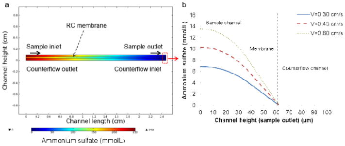
Numerical simulation of ammonium sulfate (initial concentration 250 mmol/L) transport in the microfluidic device to verify adequate ion removal: (a) depiction of the ammonium sulfate concentration throughout the microdialysis segment of the device (channel length scaled by a factor of 10 for more rapid computation), and (b) concentration profile of ammonium sulfate along the sample channel, RC membrane, and counterflow channel at the exit of the dialysis region for flow velocities varying from 0.3 cm/s to 0.6 cm/s.
A potential concern with the continuous flow microdialysis element is potential alteration of liposome size during dialysis. Prior to buffer exchange, the microfluidic-synthesized liposomes were found to be 80.8 nm in diameter with a very low polydispersity index (PDI) of 0.049. Size distributions measured before and after on-chip microdialysis revealed only a slight increase in mean vesicle size to 91.5 nm, confirming that the on-chip counterflow microdialysis element did not significantly affect the liposome size. Buffer counterflow eluent was also collected and examined via light scattering. No detectable signal was observed, revealing that intact liposomes do not escape the membrane and enter the counterflow during microdialysis.
Anthracyclines represent an important class of drugs for liposomal encapsulation. Received by nearly every patient undergoing systemic cancer chemotherapy, anthracyclines are among the most utilized and effective antitumor drugs developed to date.28 Liposomal forms of anthracyclines can provide increased efficacy with significantly reduced toxicity,29 enhancing the overall clinical value of the drugs.30 Liposomal encapsulation of the anthracycline doxorubicin (DOX) has proven particularly successful for treatment of a range of cancers, with remote loading of DOX into preformed liposomes being a key feature of this success.27 Here we use DOX as a model drug encapsulant to investigate the potential for continuous flow remote drug loading using the microfluidic process.
Initial testing was performed using preformed liposomes injected into the counterflow microdialysis chip to form the desired transmembrane ion gradient, followed by on-chip introduction of AO as a suitable analog to DOX. AO is an amphipathic weak base with similar properties to DOX, and is known to behave similarly to DOX during remote loading with ammonium sulfate gradients.11,13,31,32 Figure 5a presents the measured final D/L and encapsulation efficiency (EE) for AO-loaded liposomes prepared using an initial D/L of 0.44 when varying the sample velocity from 0.18 cm s−1 to 0.45 cm s−1, for a total residence time within the mixing channel ranging from 4.25 min to 1.7 min, respectively. While a slight increase in both final D/L and EE was observed with increasing flow rate, overall remote loading using the microfluidic approach exhibited little dependence on flow velocity. In contrast, the initial concentration of drug compound introduced following ion exchange had a substantial effect on the final D/L (Figure 5b). By increasing the initial D/L level, final D/L values up to 1.3 were achieved. This effect is likely due to the significantly decreased diffusion lengths with increasing AO concentration and thus a greater quantity of AO may be loaded when the initial concentration is higher. Reported D/L values for liposomal anthracyclines produced via conventional bulk-scale remote loading are typically below 0.25,21 significantly less than the levels achieved using the microfluidic process. The higher optimal D/L observed for the microfluidic platform can be explained by the rapid introduction of AO following buffer exchange, together with the use of a high initial D/L and effective on-chip mixing between liposomes and encapsulant for decreased diffusion lengths during drug loading in the presence of a stable and steep ion gradient. Encapsulation efficiency of the resulting liposomes was observed to increase with initial D/L, then began to diminish for initial D/L values exceeding 2.17. This result is in accordance with previous studies based on bulk-scale loading based on longer loading periods (hours to days), which suggest EE peaks at an initial D/L of 0.95 and decreases at higher ratios.32 This behavior is due to insufficient intravesicular loading capacity above some limiting D/L level, resulting in a lower EE as drug concentration is further increased. The higher optimal D/L observed for the microfluidic platform is believed to result from the highly efficient formation of a transmembrane ion gradient due to rapid microfluidic buffer exchange, together with immediate interactions between the vesicles and the amphipathic molecules to be loaded. The steep transmembrane ion gradient achieved through rapid buffer exchange may enable higher D/L ratios to be achieved through microfluidic remote loading versus bulk scale processes.
Figure 5.
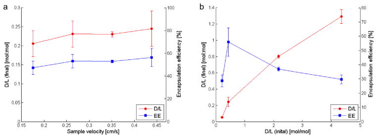
Relationships between (a) sample velocity and (b) initial AO concentration on final encapsulated concentration and loading efficiency. Microfluidicgenerated liposomes, 80.8 nm in diameter, were formed in a separate chip for this experiment.
After demonstrating buffer exchange, pH adjustment, and remote loading of AO into preformed vesicles using the microfluidic approach, liposome synthesis in-line with microdialysis and remote loading of both AO and DOX was performed using an integrated device combining all of the process steps in a single flow-through chip. The resulting liposomes were first characterized for diameter when AO, DOX or buffer was alternately injected as the drug loading phase (Figure 6). Under the flow conditions used in these experiments, the resulting liposomes exhibited an average diameter of 225.5 nm ± 44.8 nm for the case of buffer without amphipathic encapsulant, while a reduction in liposome size to 190.9 nm ± 43.0 nm for DOX-loaded liposomes and 191.5 nm ± 33.4 nm for AO-loaded liposomes was observed. The reduction in liposome size of approximately 15% after remote loading may reflect a change in morphology to a characteristic “coffee bean” shape resulting from drug crystallization within the vesicles,[12] leading to altered signals during dynamic light scattering. Confirmation of drug crystallization was verified through cryogenic transmission electron microscopy (cryoTEM) imaging. A cryoTEM image of a DOX-loaded liposome is shown inset in Figure 6.
Figure 6.

a) Volume-weighted size distributions from remote loading of DOX and AO into liposomes in-line with synthesis and microdialysis for buffer exchange in comparison to unloaded liposomes (buffer only) generated by the same microfluidic device. A cryoTEM image of a DOX-loaded liposome formed in-line with synthesis is shown inset.
A summary of measured final D/L values following AO and DOX loading within the integrated microfluidic device is presented in Table 1. Prior results for the case of AO loading using preformed liposomes generated in a separate chip are also shown for comparison. An initial D/L of 0.44 was selected for DOX, as this ratio was found to maximize loading efficiency in initial experiments using AO (Figure 4). The DOX loaded liposomes generated by the microfluidic device had a final D/L of 0.32 ± 0.03 (standard deviation), which exceeds the typical D/L of 0.25 or less achieved by bulk remote loading employing overnight incubation.12 The total on-chip residence time of within the microfluidic device was less than 3 min. In addition, initial D/L values of 0.22 and 0.44 were used for testing AO loading, resulting in final D/L values of 0.06 ± 0.01 and 0.32 ± 0.11, respectively.
Table 1.
Summary of D/L and EE measurements for AO loaded liposomes (preformed liposomes produced in a separate chip) and DOX and AO loaded liposomes (formed in-line with synthesis in a single integrated chip). Similar results were achieved for DOX and AO loading within the integrated device. Slightly higher final D/L and EE values were observed when remote loading was performed in-line with liposome synthesis. The in-line remote loading process achieves D/L levels exceeding typical values of 0.25 or below achieved by day-long bulk incubation, but with only a 3 minute on-chip residence time.
| Loading case | Liposome diameter (nm) | Drug/agent | D/L (initial) | D/L (final) | EE (%) |
|---|---|---|---|---|---|
| Preformed | 80.8 ± 17.9 | AO | 0.22 | 0.05 ± 0.01 | 23.5 ± 4.2 |
| 0.44 | 0.24 ± 0.06 | 55.9 ± 10.0 | |||
| In-line | 191.5 ± 33.4 | AO | 0.22 | 0.06 ± 0.01 | 26.9 ± 2.2 |
| 0.44 | 0.32 ± 0.11 | 69.8 ± 18.0 | |||
| 190.9 ± 43.0 | DOX | 0.44 | 0.32 ± 0.03 | 71.8 ± 4.2 |
Encapsulation efficiency using the integrated system was also evaluated. Referring to Table 1, the DOX-loaded liposomes yielded an EE of approximately 72%, lower than typical values for conventional remote loading which can exceed 99%.33 Lower encapsulation efficiency compared to bulk-scale remote loading is not surprising, since the incubation time is up to 300 times lower within the microfluidic system. Regardless, this is an aspect of the microfluidic approach which must be improved to minimize drug waste, for example by implementing a method for capturing and recycling drug in an additional on-chip stage following remote loading. In addition to reducing manufacturing costs by reducing waste of valuable drug compounds, optimizing loading conditions could also eliminate the need for off-chip purification, enabling real-time production of stably encapsulated, highly concentrated liposomal drugs at or near the point of care.
Direct comparison of in-line system performance with the previous results from remote loading using preformed liposomes is hampered by the different sizes of each liposome population. When performing in-line remote loading, fluidic coupling between the upstream liposome formation zone and downstream microdialysis and drug loading zones demands careful design of the channel dimensions, together with appropriate selection of inlet flow rates. Liposome size and polydispersity are both impacted by the buffer:lipid flow rate ratio, overall volumetric flow rate, and microchannel dimensions selected for effective liposome self-assembly during hydrodynamic flow focusing.16–20 However, these same parameters also affect microdialysis and remote drug loading performance. While channel dimensions for each functional element in the system can be designed independently, allowing a degree of decoupling between these constraints, the current microfabrication process used for device manufacture presents some limitations. For example, to avoid sagging of the microdialysis membrane, a maximum channel width of 1.2 mm was used for the buffer exchange zone. Similarly, total volumetric flow rates were minimized to prevent delamination of the hybrid microfluidic device due to excessive internal fluid pressure. As a result of these constraints, liposomes formed using the on-line system were approximately twice the diameter of their preformed counterparts. Although residual pH gradients decrease with decreasing vesicle size due to decreased intravesicular volumes, it has been shown that this effect can be circumvented by including a buffering capacity greater than 300 mmol L−1.34 Additionally, given the significantly larger volume of the in-line liposomes, it is notable that both the final D/L and EE values for in-line encapsulation were comparable to the case of preformed liposome loading, with slight increases in both values for the larger liposomes. This further emphasizes the observation that the initial D/L is the dominant parameter that defines encapsulation performance during remote loading within the continuous flow microfluidic system.
Finally, we note that liposome concentrations achieved by the microfluidic system are typically in the range of 1010~1012 liposomes/mL, depending on experimental parameters including lipid concentration and flow rate ratio. For comparison, reported concentration levels generated by typical bulk production methods range from 107~1012 liposomes/mL,35–37 indicating that the microfluidic technique can provide a viable alternative for liposomal drug preparation without requiring significant additional steps to further concentrate the vesicles following on-chip processing.
Conclusion
By combining liposome synthesis via microfluidic flow focusing, membrane microdialysis for buffer exchange, and in-line introduction of amphipathic weak bases for remote loading within a single microfluidic device, this study converts a conventional multi-step bulk-scale process requiring hours to days of labor into a microscale process which requires a total on-chip residence time of approximately 3 minutes. By taking advantage of the reduced diffusive length scales characteristic of microscale flows, the microfluidic method implements remote loading as a seamless continuous flow process, with the potential to simplify and increase the robustness of this critical step in nanoliposomal drug production. The further ability to perform integrated liposome formation using hydrodynamic flow focusing prior to formation of a transmembrane ion gradient for remote drug loading allows the entire sequence of steps required for liposomal drug production to be performed as a single in-line and continuous flow process. The microfluidic method demonstrated here enable exceptionally high drug loading levels, with D/L values above unity easily achieved. Future optimization of device design and flow conditions are expected to further improve encapsulation efficiency, enabling just-in-time production of purified liposomal drug formulations with minimal drug waste.
Acknowledgments
The authors thank Dr. Peter Swaan at the University of Maryland School of Pharmacy for Malvern Zetasizer access. This research was supported by NIH grants R21EB011750 and R21EB009485, NSF grant CBET0966407, and a NIST-ARRA Fellowship Program administered by the University of Maryland. CryoTEM imaging was performed at the Nanoscale Imaging, Spectroscopy, and Properties (NISP) Laboratory of the Maryland NanoCenter at the University of Maryland, College Park.
References
- 1.Allen TM, Cullis PR. Adv Drug Deliv Rev. 2013;65:36–48. doi: 10.1016/j.addr.2012.09.037. [DOI] [PubMed] [Google Scholar]
- 2.Cullis PR, Mayer LD, Bally MB, Madden TD, Hope MJ. Adv Drug Deliv Rev. 1989;3:267–282. [Google Scholar]
- 3.Abraham SA, Waterhouse DN, Mayer LD, Cullis PR, Madden TD, Bally MB. Methods Enzym. 2005;391:71–97. doi: 10.1016/S0076-6879(05)91004-5. [DOI] [PubMed] [Google Scholar]
- 4.Barenholz Y. Curr Opin Colloid Interface Sci. 2001;6:66–77. [Google Scholar]
- 5.Mayer LD, Bally MB, Cullis PR. Biochim Biophys Acta - Biomembr. 1986;857:123–126. doi: 10.1016/0005-2736(86)90105-7. [DOI] [PubMed] [Google Scholar]
- 6.Harrigan PR, Wong KF, Redelmeier TE, Wheeler JJ, Cullis PR. Biochim Biophys Acta. 1993;1149:329–38. doi: 10.1016/0005-2736(93)90218-o. [DOI] [PubMed] [Google Scholar]
- 7.Li X, Hirsh DJ, Cabral-Lilly D, Zirkel A, Gruner SM, Janoff AS, Perkins WR. Biochim Biophys Acta - Biomembr. 1998;1415:23–40. doi: 10.1016/s0005-2736(98)00175-8. [DOI] [PubMed] [Google Scholar]
- 8.Deamer DW, Prince RC, Crofts AR. Biochim Biophys Acta. 1972;274:323–335. doi: 10.1016/0005-2736(72)90180-0. [DOI] [PubMed] [Google Scholar]
- 9.Nichols JW, Deamer DW. Biochim Biophys Acta. 1976;455:269–271. doi: 10.1016/0005-2736(76)90169-3. [DOI] [PubMed] [Google Scholar]
- 10.Madden TD, Janoff AS, Cullis PR. Chem Phys Lipids. 1990;52:189–198. doi: 10.1016/0009-3084(90)90114-7. [DOI] [PubMed] [Google Scholar]
- 11.Haran G, Cohen R, Bar LK, Barenholz Y. Biochim Biophys Acta. 1993;1151:201–15. doi: 10.1016/0005-2736(93)90105-9. [DOI] [PubMed] [Google Scholar]
- 12.Fritze A, Hens F, Kimpfler A, Schubert R, Peschka-Süss R. Biochim Biophys Acta. 2006;1758:1633–40. doi: 10.1016/j.bbamem.2006.05.028. [DOI] [PubMed] [Google Scholar]
- 13.Clerc S, Barenholz Y. Biochim Biophys Acta - Biomembr. 1995;1240:257–265. doi: 10.1016/0005-2736(95)00214-6. [DOI] [PubMed] [Google Scholar]
- 14.Lasic DD, Ceh B, Stuart MC, Guo L, Frederik PM, Barenholz Y. Biochim Biophys Acta. 1995;1239:145–56. doi: 10.1016/0005-2736(95)00159-z. [DOI] [PubMed] [Google Scholar]
- 15.Mayer LD, Tai LCL, Ko DSC, Masin D, Ginsberg RS, Cullis PR, Bally MB. 1989:5922–5930. [PubMed] [Google Scholar]
- 16.Jahn A, Vreeland WNNWN, Gaitan M, Locascio LEELE. J Am Chem Soc. 2004;126:2674–2675. doi: 10.1021/ja0318030. [DOI] [PubMed] [Google Scholar]
- 17.Jahn A, Vreeland WN, DeVoe DL, Locascio LE, Gaitan M. Langmuir. 2007;23:6289–6293. doi: 10.1021/la070051a. [DOI] [PubMed] [Google Scholar]
- 18.Jahn A, Reiner JE, Vreeland WN, DeVoe DL, Locascio LE, Gaitan M. J Nanoparticle Res. 2008;10:925–934. [Google Scholar]
- 19.Jahn A, Stavis SM, Hong JS, Vreeland WN, DeVoe DL, Gaitan M. ACS Nano. 2010;4:2077–2087. doi: 10.1021/nn901676x. [DOI] [PubMed] [Google Scholar]
- 20.Hood RR, Shao C, Omiatek DM, Vreeland WN, DeVoe DL. Pharm Res. 2013;30:1597–607. doi: 10.1007/s11095-013-0998-3. [DOI] [PMC free article] [PubMed] [Google Scholar]
- 21.Drummond DC, Meyer O, Hong K, Kirpotin DB, Papahadjopoulos D. Pharmacol Rev. 1999;51:691–743. [PubMed] [Google Scholar]
- 22.Stephan K, Pittet P, Renaud L, Kleimann P, Morin P, Ouaini N, Ferrigno R. J Micromechanics Microengineering. 2007;17:N69–N74. [Google Scholar]
- 23.Pall Corporation. 2012 [Google Scholar]
- 24.Leaist DG, Hao L. J Solution Chem. 1992;21:345–350. [Google Scholar]
- 25.Kano K, Fendler JH. Biochim Biophys Acta. 1978;509:289–299. doi: 10.1016/0005-2736(78)90048-2. [DOI] [PubMed] [Google Scholar]
- 26.Zook JM, Vreeland WN. Soft Matter. 2010;6:1352. [Google Scholar]
- 27.Barenholz YC. J Control Release. 2012;160:117–34. doi: 10.1016/j.jconrel.2012.03.020. [DOI] [PubMed] [Google Scholar]
- 28.Hortobágyi GN. Drugs. 1997;54:1–7. doi: 10.2165/00003495-199700544-00003. [DOI] [PubMed] [Google Scholar]
- 29.Minotti G, Menna P, Salvatorelli E, Cairo G, Gianni L. Pharmacol Rev. 2004;56:185–229. doi: 10.1124/pr.56.2.6. [DOI] [PubMed] [Google Scholar]
- 30.Allen TM, Martin FJ. Semin Oncol. 2004;31:5–15. doi: 10.1053/j.seminoncol.2004.08.001. [DOI] [PubMed] [Google Scholar]
- 31.Clerc S, Barenholz Y. Anal Biochem. 1998;259:104–11. doi: 10.1006/abio.1998.2639. [DOI] [PubMed] [Google Scholar]
- 32.Zucker D, Marcus D, Barenholz Y, Goldblum A. J Control Release. 2009;139:73–80. doi: 10.1016/j.jconrel.2009.05.036. [DOI] [PubMed] [Google Scholar]
- 33.Lewrick F, Süss R. Methods Mol Biol. 2010;605:139–45. doi: 10.1007/978-1-60327-360-2_9. [DOI] [PubMed] [Google Scholar]
- 34.Mayer LD, Tai LCL, Bally MB, Mitilenes GN, Ginsberg RS, Cullis PR. Biochim Biophys Acta. 1990;1025:143–51. doi: 10.1016/0005-2736(90)90091-2. [DOI] [PubMed] [Google Scholar]
- 35.Chen H, Hu Q-Y, Yue-Zheng, Jiang J-H, Shen G-L, Yu R-Q. Anal Chim Acta. 2010;657:204–9. doi: 10.1016/j.aca.2009.10.036. [DOI] [PubMed] [Google Scholar]
- 36.Hitchcock KE, Caudell DN, Sutton JT, Klegerman ME, Vela D, Pyne-Geithman GJ, Abruzzo T, Cyr PEP, Geng YJ, McPherson DD, Holland CK. J Control Release. 2010;144:288–95. doi: 10.1016/j.jconrel.2010.02.030. [DOI] [PMC free article] [PubMed] [Google Scholar]
- 37.Cool SK, Geers B, Roels S, Stremersch S, Vanderperren K, Saunders JH, De Smedt SC, Demeester J, Sanders NN. J Control Release. 2013;172:885–93. doi: 10.1016/j.jconrel.2013.09.014. [DOI] [PubMed] [Google Scholar]