Abstract
X-ray Luminescence Tomography (XLT) has recently been proposed as a new imaging modality for biological imaging applications. This modality utilizes phosphor nanoparticles which luminesce near-infrared light when excited by X-ray photons. The advantages of this modality are that it uniquely combines high sensitivity of radioluminescent nanoparticles and high spatial localization of collimated X-ray beams. Currently, XLT has been demonstrated using X-ray spatial encoding to resolve the imaging volume. However, there are applications where the X-ray excitation may be limited by geometry, where increased temporal resolution is desired, or where a lower dose is mandatory. This paper extends the utility of XLT to meet these requirements by incorporating a photon propagation model into the reconstruction algorithm to recover dimensions remaining in an X-ray limited angle (LA) geometry. This enables such applications as image-guided surgery, where the ability to resolve lesions at depths of several centimeters can be the key to successful resection. The hybrid X-ray/diffuse optical model is first formulated and then demonstrated in a breast-sized phantom, simulating a breast lumpectomy geometry. Both numerical and experimental phantoms are tested, with lesion-simulating objects of various sizes and depths. Results show localization accuracy with median error of 2.2mm, or 4% of object depth, for small 2–14mm-diameter lesions positioned from 1cm to 4.5cm in depth. This compares favorably with fluorescence optical imaging, which is not able to resolve such small objects at this depth. The recovered lesion size has lower size-bias in the X-ray excitation direction than the optical direction, which is expected due to the increased optical scatter. However, the technique is shown to be quite invariant in recovered size with respect to depth, as the standard deviation is less than 2.5mm. Sensitivity is a function of dose; radiological doses are found to provide sufficient recovery for μg/ml concentrations, while therapy dosages provide recovery for ng/ml concentrations. Experimental phantom results agree closely with the numerical results, with positional errors recovered within 8.6% of the effective depth for a 5mm object, and within 5.2% of the depth for a 10mm object. Object size median error is within 2.3% and 2% for the 5mm and 10mm objects, respectively. For shallow-to-medium depth applications where optical and radio-emission imaging modalities are not ideal, such as in intra-operative procedures, LAXLT may be a useful tool to detect molecular signatures of disease.
1. Introduction
Imaging plays a vital role in the management of cancer care, for detection, staging, intervention, and monitoring of treatment response. Despite its ubiquitous use elsewhere, the role of imaging in surgery is limited, as it is dominated by C-arm fluoroscopy and optical endoscopy. These tools are appropriate for visualizing tissue structure, yet are limited in their sensitivity to microscopic disease. This limitation affects such procedures as surgical breast lumpectomy, as many studies have found that surgeons are unable to remove all tumor tissue present in the surgical field (for example, Gibson et al. identified residual tumor in 55% of the cases[1]). The risks of local failure are high, as local failure often leads to distant metastasis [2]. Thus, there is a need for tools to provide surgeons with more sensitive, more specific image-guidance.
This need may be fulfilled with molecular imaging, which promises to image molecular and cellular processes, and may allow the early identification of disease or status of disease progression and treatment [3]. Developing these tools for the operating room would aid a physician during an intervention, by allowing the clinician to identify near-microscopic regions of disease, such as at the tumor margin. Ideally, this tool would be able to image at a depth of several centimeters, so that disease buried beneath the superficial layers could be identified. Several potential applications for this technology could be in removing occult disease in breast[4, 5], brain[6] and hepatic tumors[7], where imaging is currently being incorporated into the clinic, and new innovations may be readily translated.
This paper develops and demonstrates a novel X-ray Luminescence Tomographic (XLT) method that is uniquely suited for image-guided surgical applications. This method, Limited-Angle XLT (LAXLT), utilizes a photon propagation model to enable XLT for surgical guidance, where XLT’s advantages are the clearest for translation into the clinic. XLT has been recently introduced[8] and demonstrated in simulation and in phantoms [9, 10]. This imaging modality utilizes nano-sized phosphors which emit optical near-infrared light upon X-ray excitation [11, 12]. Attaching these phosphors to molecular probes (e.g. antibodies and peptides) that target molecular markers specific to tumors, such as angiogenesis markers like epidermal growth factor receptor[13], or αvβ3-integrin [14, 15] expression could allow the surgeon to differentiate between normal and cancerous tissue. XLT has several advantages to current molecular-sensitive imaging modalities: emission imaging techniques, such as gamma cameras, are limited in their ability to discriminate depth due to the limited angles that may be imaged during surgical procedures[16]; optical imaging, on the other hand, has the ability to provide depth localization, and is currently under investigation for surgical guidance [6, 4, 17], yet is limited in its ability to image deeper than ~1cm[18]. Depth is important to discern to determine occult lesions lying under the superficial layer, and to determine the feasibility of surgical removal of a lesion.
XLT utilizes the extremely low-scatter of X-rays compared to optical fluorescence imaging to enable higher spatial resolution. A thin pencil-beam of collimated X-rays may be maintained while the X-rays propagate through tissue of several cm; this spatial localization is in contrast to optical excitation, which is highly attenuated and scattered[19]. By rotating the X-ray (or similarly the phantom) to cover all angular projections, the resolving power is limited merely by the width of the beam (up to the diffraction of the X-ray). A numerical analysis demonstrated that 2.25cm deep objects as small as 1mm (using a 1mm beam width) with a nanoparticle concentration of 0.4pM could be resolved; incraesing dose increased the sensitivity[9]. However, there are applications where the X-ray excitation may be limited by geometry, where increased temporal resolution is desired, or where a lower dose is mandatory; one such application is intraoperative breast cancer lumpectomy, where it may not be possible or desirable to irradiate over the full projection space. In these cases, it would be beneficial to irradiate over a limited projection space, and use the ability of the optical detectors to resolve the remaining dimensions. This technique could also have utility in decreasing dose to the tissue, as fewer irradiation beamlets are needed to resolve the volume.
This paper develops a reconstruction methodology for utilizing XLT to perform depth-resolved imaging in a geometry appropriate for tumor-resection applications. This method develops a hybrid X-ray/optical reconstruction, which allows XLT spatial encoding in a limited angle geometry, and diffuse optical spatial discrimination for the remaining dimensions. This technique augments that of Pratx et al, who encoded all spatial dimensions [9]; such a technique is more suitable for such applications as small-animal imaging. The advantage of this new approach is that enables XLT in surgical applications such as breast or brain excision, and may reduce dose. The performance of this technique is examined in both numerical and experimental phantoms for various object sizes and positions, within a geometry that mimics breast and brain intraoperative geometries.
2. Methods
2.1 Experimental Setup
The equipment used for this study consisted of an X-ray radiation source to excite the phosphors, and an optical detector to sample the photon fluence. During acquisition, the radiation source is collimated into a thin slice as described by Pratx et al.[9] to excite a plane shaped volume. An optical camera samples the emitted light. This schematic is shown in Figure 1a. The experimental setup is shown in Figure 1b.
Figure 1.
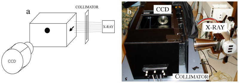
(a) Schematic of LAXLT while imaging a phantom with a single spherical object (b) Experimental setup used in this study. A black-box was used to enclose the phantom (not shown) and eliminate ambient light from the experiment.
The X-ray source used for the measurements in this paper was a 50kVp X-ray superficial unit (Pantak Therapax-150, Elimpex, AT) with a 10cm exit-diameter cone applicator. This cone was placed 17.5cm from surface of the phantom. The beam was collimated to 1mm wide (verified optically) by carefully positioned 50mm thick lead bricks. A high sensitivity EM-CCD camera (Pro-EM, Princeton Instruments, NJ) with a F/1.4 lens was positioned ~20 cm from the surface of the phantom. This distance was chosen to minimize X-ray photon noise[8]. As an alternative, optically clear leaded acrylic or leaded glass could be placed between the camera and the sample and used to reduce X-ray noise on the CCD and allow the camera to be placed closer to the sample to collect more light.
2.2 Image Formation
2.2.1 X-ray Luminescence Emission Forward Model
To determine the concentration of nanophosphors, the radiation (X-ray and optical) must be modeled. The emission of X-ray excitable nanophosphors is linearly dependent on the dose imparted to the tissue [8], d (units of Gy), the fractional efficiency of the phosphor in converting ionizing energy to optical emission, Γ, and the concentration, c (units of mg/ml). The luminescent photon density from the nanophosphors, Φ, due to an incident radiation beam is therefore:
| (1) |
Determining the total ionization energy imparted to the tissue (dose) is a procedure that requires calibration to incorporate the properties of the radiation emitted by the X-ray system. This calibration is system-specific, taking into account tube potential, geometry, X-ray tube target, and filter material; these factors taken together form an X-ray spectrum, known as the beam quality. The dose at depth is determined using measurements from a calibrated ionization chamber in a phantom and composed into a look-up-table, the Percent Depth Dose (PDD) curves. This system-wide calibration is performed periodically[20]. Using the PDD curves, dose at a specific depth in the tissue can be determined by knowing the source-to-surface distance between the X-ray tube and the tissue. This method can have high quantitative accuracy of 1–2% [21]. Another method to accurately determine dose is through Monte-Carlo methods, which model the system, including the above factors and also including patient anatomy. This method can calculate dose with high accuracy as long as comprehensive modeling of beam quality is performed[22]. In this study, we used the PDD curves to determine dose.
2.2.2 Diffuse Optical Forward Model
Images acquired at the tissue surface are input into a photon propagation model to determine the phosphor distribution. The images from the CCD camera are first processed to remove X-ray noise using a simple gradient-threshold algorithm, and then input into the algorithm as the data. The propagation of optical light can be approximated by the lossy photon Diffusion Equation (DE) [23], which yields the photon density in tissue. The DE is valid for many soft human tissues, including the breast, lung, prostate, brain, etc. [24]. Following excitation from X-ray radiation, the time-independent luminescence photon density emitted from the nanophosphors is:
| (2) |
where φ(r) is the photon fluence at position r, in units of photons per area per time, and Φ(r) is the photon density, in units of photons per volume per time. Photon propagation is affected by the absorption and diffusion coefficients of the tissue, μa and D, respectively, which are dependent on wavelength. The diffusion coefficient, D, is defined as , where μs′ is the reduced scattering coefficient of the emitted photons. A type III boundary condition is used to model the photon fluence at the boundary, −D∇φ·n̂ = αφ, where α defines the internal reflection of the light at the tissue boundary due to the index of refraction mismatch between tissue and air[25][26], and the unit vector n is normal to the surface of the phantom. Because no unique solution exists for (2) with arbitrary boundaries, equation (2) is approximated with the Finite Element Method(FEM)[23]. This problem is similar to the diffuse optical fluorescence model introduced by Jiang[27], and is adapted here.
As described by Jiang, the photon emission may be approximated with the FEM by:
| (3) |
where A is the FEM approximation of the physics of photon propagation (the right-hand-side of equation (2)) and b is the approximation to the light source (the left-hand-side of equation (2)). More specifically, the physics of the photon propagation is approximated with the FEM by:
| (4) |
where ψi,j are the volume elements that discretize the imaging domain and form a geometrical mesh defined over the entire imaging domain. A is integrated over this imaging domain. The source (in this case, the light emitted from the phosphors which were excited by the X-ray source) and boundary integral are approximated with the FEM by:
| (5) |
The time component of the luminescence lifetime is ignored since the measurements in this work are from an integrating CCD camera, and the measurement time is much greater than the luminescence lifetime; effects from the minimal afterglow of the phosphors are ignored.
The FEM model, G, is used to generate estimates for the photon fluence given the optical properties of the tissue, the concentration of phosphors, c, and the FEM mesh. An estimate for the photon fluence, φ, can be calculated by solving equation (3):
| (6) |
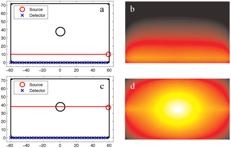
In this paper, the imaging domain is known, and is assumed that the endogenous optical tissue properties are known, so the model is dependent only on the unknown, c. Figure 2 shows the optical photon fluence for a numerical phantom with 100:1 phosphor concentration between an object and the background. Two different source configurations are shown, each with the X-ray direction of propagation in the horizontal (left/right) direction. In Figure 2a–b, the X-ray source, indicated by the red circle, irradiates a horizontal line passing through the background, whereas in Figure 2c–d, the X-ray irradiates the horizontal line passing through the middle of the phosphor-containing object.
Figure 2.
(a) Numerical phantom with a single object located at the center of the domain, and a 10:1 contrast in phosphor between the object and background. The X-ray source irradiates the domain along the long-axis of the phantom at a position of X=10, Y=−60:60. (b) The emission fluence field of (a). (c) Numerical phantom with the X-ray source irradiating at a position of X=40, Y=−60:60. (d) The emission fluence field of (c).
2.2.3 X-ray Nanophosphor Concentration Reconstruction
The goal of X-ray Luminescence Tomography is to determine the phosphor distribution. This spatial distribution can be determined by minimizing the difference between the measured photon flux from the camera, φM (r), and the simulated photon flux, φS (r) at identical sample locations. This is accomplished by minimizing the L2-norm of the objective function in an optimization routine:
| (7) |
where Ω is the objective function to minimize. Because of the large dynamic range, the first term in (7) is formulated from the natural logs of the photon fluxes. This is an underdetermined problem, as measurements are made only at the boundary. Because this problem is underdetermined, the model, G, is linearized with a Taylor approximation and formed into an iterative algorithm as:
| (8) |
where G′ is the partial differential of the model with respect to the concentration, also known as the Jacobian, J. Minimizing equation (7) with respect to c and substituting G(ci) from equation (8) into φ S and J for G′ yields:
| (9) |
Solving for the concentration yields:
This problem is ill-posed, so it is solved using the Levenberg-Marquardt [28] algorithm, which includes a stabilization parameter, λ, in the inversion to avoid singularities:
| (10) |
Equation (5) is iterated until a minima is reached (the L2 norm of the update is less than 1% of the previous iteration), or until 15 iterations are performed, whichever occurs earlier. The stabilization parameter is reduced at each iteration as the algorithm approaches the minimum and converges on the solution.
Although this study focused on applications where a single angle is ideal, note that this algorithm is not limited to a single angle. Thus, this algorithm is appropriate for any sparse-angle geometry.
2.3 Phantom Study
The performance of the experimental setup and the reconstruction algorithm were tested by varying the size and location of a lesion-simulating object. The relationships between source-object and detector-object distance on resolving an object of various sizes were determined with both numerical and experimental phantoms. The metrics used to determine system performance were object location and object size. Location error in both the X-ray excitation and optical read-out dimensions was determined by calculating the distance between the true centroid of the lesion and the location of the maximum recovered value of the phantom. Object size in both the X-ray excitation and optical read-out dimensions were determined by calculating the full width at half maximum (FWHM) of the object in these dimensions. Concentration sensitivity and contrast recovery were also examined.
2.3.1 Numerical Phantoms
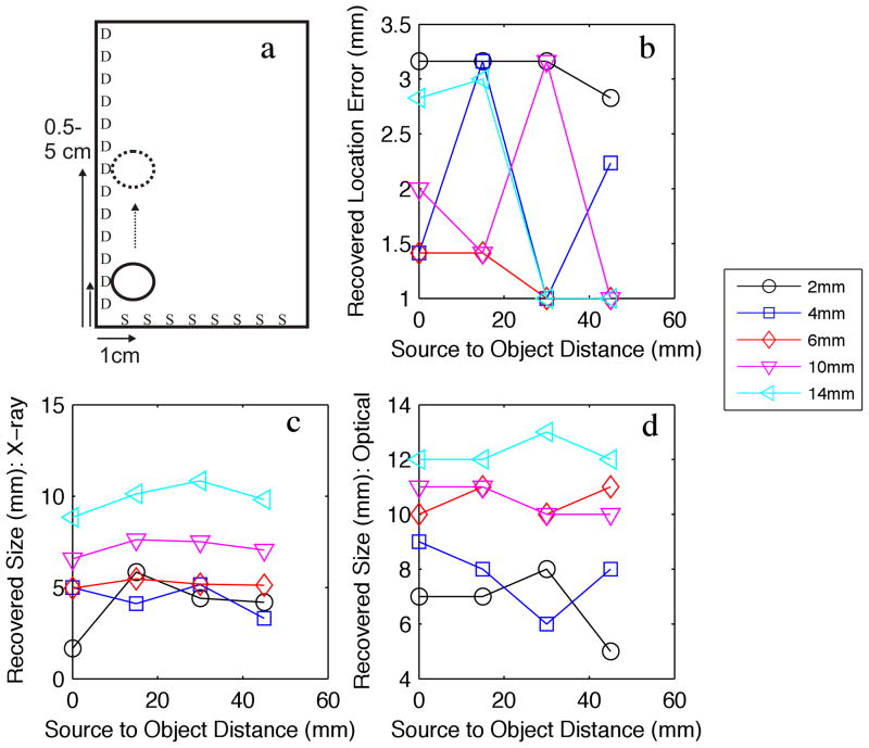
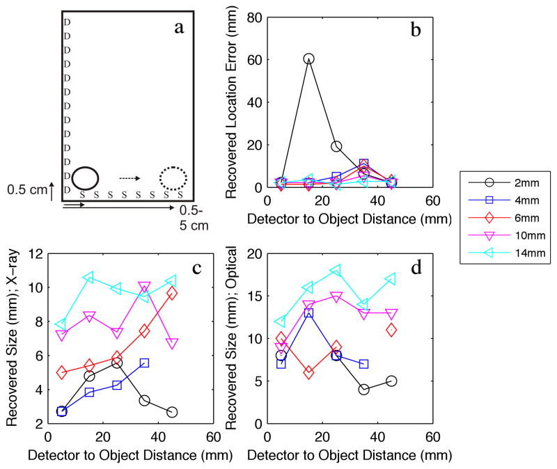
Numerical phantoms were utilized to test the position-accuracy, object size-accuracy, and sensitivity of the algorithms. The position and object-size phantoms investigated the recovery of simulated tumors with 10:1 contrast between the object and the background and phosphor concentrations of 10μg/ml. These lesions varied in size between 2–14mm, and were placed at different locations in the phantom, as depicted in Figures 3a and 4a (note the multiple arrows, which indicate the minimum and maximum extent of the object locations investigated). Sufficient dose (1cGy) was given to yield signal-to-noise (SNR) greater than 10 for each object position - this methodology allowed a performance test of the algorithm for all object positions.
Figure 3.
(a) Numerical phantom experiment examining the effect of moving a variable sized object away (4 positions, indicated by the arrows) from the X-ray source plane (S), while keeping the distance from the detection plane (D) fixed. (b) Recovered object location error. (c) Recovered object diameter FWHM with respect to the X-ray source dimension. (d) Recovered object diameter FWHM with respect to the optical detection dimension.
Figure 4.
(a) Numerical phantom experiment examining the effect of moving a variable sized object away (8 positions, indicated by the arrows) from the optical detection plane (D), while keeping the distance from the X-ray source plane (S) fixed. (b) Recovered object location error. (c) Recovered object diameter FWHM with respect to the X-ray source dimension. (d) Recovered object diameter FWHM with respect to the optical detection dimension.
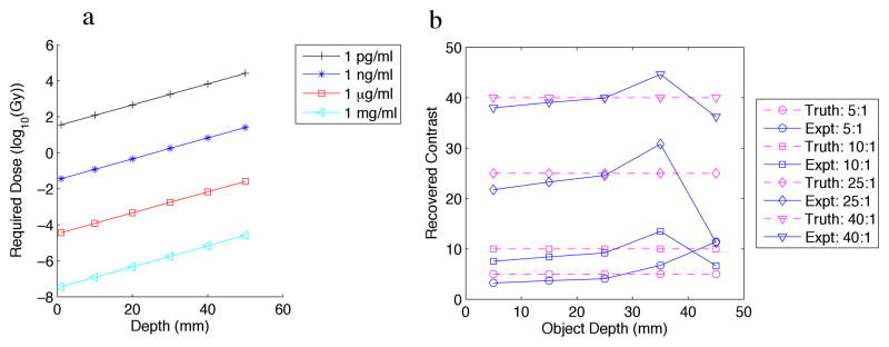
The sensitivity phantom included an object with varying concentration (Figure 5a), and varying contrast (Figure 5b). The 6mm-diameter object was placed at the center of the phantom along the dimension of the detectors (the long-axis), and moved at various depths away from the detectors. We used the phosphor properties from Kandarakis et al. [29] to obtain quantification of the emitted light efficiency for their lanthanum oxysulfide:terbium phosphor, which was 1.39×10¹⁵ optical photons/(Gy × mg). We incorporated solid-angle losses as well as losses due to lens inefficiency (DO-1795, Navitar Imaging Solutions, Rochester, NY). SNR below 10 was assumed to be too low to detect.
Figure 5.
(a) Numerical phantom experiment examining the effect of: (a) variable object to background contrast and (b) variable concentration, of a 6mm-diameter object vs. depth from the detection plane.
All phantoms were 2-dimensional, and measured 12cm x 6cm. Detectors were placed along the long-axis of the phantom, while the collimated X-ray source, 1mm wide, was scanned along the short axis. The phosphor used for this experiment mimicked GOS:Eu, demonstrated in X-ray luminescence imaging in a previous study, which has a strong luminescence emission at ~618nm. Background optical properties were similar to that of breast tissue [30] (μa = 0.0027, μs′ = 0.717).
2.3.2 Experimental Phantom
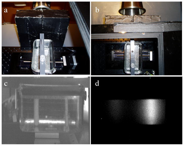
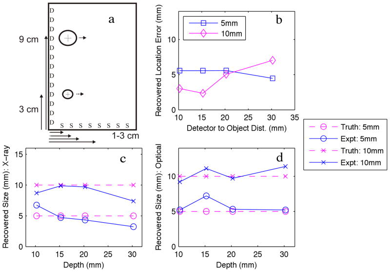
The experimental phantom is shown in Figure 6. Figure 6a–b show the relative layout of the objects in the phantom, while Figure 6c shows the camera-eye view of the phantom. Figure 6d shows an image of the phantom while the phantom is irradiated by the X-ray beam. The optically clear acrylic phantom, measuring 12cm x 6cm, was filled with india ink to mimic optical absorption, and intralipid to mimic optical scatter, at the appropriate concentrations. The optical properties were: (μa = 0.0027, μs′ = 0.717, as determined from a diffuse optical spectroscopy system). GOS:Eu phosphor at a concentration of 10mg/ml was added to two cylindrical inclusions, one 5mm in diameter, and one 10mm in diameter, which were located 3cm and 9cm from the edge nearest the X-ray source, respectively. The inclusions were both imaged at various depths from the edge nearest the detector: 10mm, 15mm, 20mm, 30mm; these dimensions are shown more clearly in Figure 7a. The exposure times and gains were 1.5s at gain 500, 3.5s at gain 800, 3s at gain 1000, and 7.5s at gain 1000, for increasing depth. Dose to the phantom varied depending on the phosphor depth, so that a high SNR could be acquired while the phosphors were irradiated. The doses to the phantom were 6.7 cGy, 15.6 cGy, 13.4 cGy, and 33.4 cGy, for increasing depth.
Figure 6.
Experimental phantom: (a–b) Two views from above the black-box including the phantom and collimator bricks. (c) Image taken by the high-sensitivity CCD camera of the phantom under ambient light and no irradiation, (d) CCD image with no ambient light and X-ray irradiation.
Figure 7.
(a) Experimental phantom of two objects moved away from the optical detection plane (D) at 4 positions. (b) Recovered object location error. (c) Recovered object diameter FWHM with respect to the X-ray source dimension. (d) Recovered object diameter FWHM with respect to the optical detection dimension.
3. Results
3.1 Numerical phantom results
As described above, a lesion-simulating object was placed in various locations in the volume so that the performance of LAXLT could be analyzed. The lesion location was varied with respect to the source-axis and detection-axis separately to determine the effects of source-object distance and detector-object distance on the ability to resolve the object. Figure 3 shows the results of maintaining a fixed detector-object distance while varying the source-object distance (varying depth with respect to the X-ray). These dimensions are depicted in Figure 3a. The location error for the 2–14mm objects is shown in Figure 3b. This result demonstrates the excellent ability of the algorithm to spatially resolve an object, as all errors in distance are lower than 3.5mm. Figure 3c shows the recovered object size in the direction of the X-ray excitation, which demonstrates the insensitivity with respect to depth, with an average standard deviation in the error in recovered size of 0.82mm for varying source-object distances. In Figure 3d, the recovered size of the object in the optical dimension is examined as a function of source-object depth. The algorithm is able to distinguish the varying sizes of the objects, with a standard deviation in the error in recovered size of 0.83mm for the varying source-object distance. There is a slight tendency for blurring in the optical dimension due to the scattering of the optical photons.
Figure 4 shows the effects of varying the depth of an object with respect to the optical dimension. Figure 4a shows the physical dimensions of the phantom. The object was moved from 0.5cm to 4.5cm from the detector, while remaining at a fixed distance from the X-ray source. Figure 4b shows the recovered location error of the centroid of the object with respect to depth from the optical detector. In this experiment, the ability to resolve an object of ~2mm was at the limit of the system with the 1mm collimated X-ray beam that was used. However, the objects sized 4mm and larger were resolved with higher accuracy. As expected, location error increases slightly as the depth increases, and larger objects are resolved more accurately than smaller objects. The advantage of using the X-ray is highlighted here, as even at 4.5cm in depth, the object is resolved with less than 1cm total error. Figure 4c shows the recovery of object size in the X-ray dimension, similar to Figure 3c. The mean standard deviation for the error in recovered object size was 1.36mm. Figure 4d shows that the ability to determine the size of the object in the optical dimension has increased variability compared to the X-ray dimension, as the mean standard deviation of the error in recovered size with respect to depth is 2.4mm. This larger standard deviation is consistent with object-blurring at depth from the optical detector; this is expected due to the ill-posed nature of the algorithms needed for the optical photon modeling. Similar to Figure 3d, this system is able to distinguish between the different sized objects in the optical dimension, although again, there is a tendency for dilation in the optically-resolved dimension.
Overall, the numerical phantom results show localization accuracy with median error of 2.2mm (mean of 6.3mm), or 4.1% (mean of 11.5%) of object depth for all lesions. The recovered lesion size has lower size-bias, with median error of -8.1% vs. 87.5% (mean of 19.4% and 118.3%, respectively), in the X-ray excitation direction vs. the optical direction, respectively. Again, this optical dilation is expected due to the increased optical scatter compared to X-ray. This technique is invariant in recovered size with respect to depth, as the standard deviation is less than 2.5mm.
The concentration phantom is shown in Figure 5a. The required dose (in Gy) to reach an SNR of 10 is plotted for varying concentrations. It is apparent from this calculation that a 6mm-diameter object with μg/ml concentration is detectable in this geometry with standard CT doses. With the doses currently used in IORT, concentrations to ng/ml are detectable at depth. As shown in Figure 5b, with sufficient signal, contrast can be recovered for all contrast to background ratios tested, for depths up to 45mm. Here, the advantage of the ability of the collimated X-ray to selectively excite the phosphors is clear.
3.2 Experimental phantom results
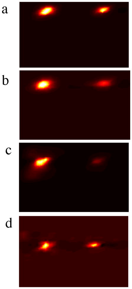
Photographs of the experimental phantom are shown in Figure 6; the schematic of the experimental phantom is shown in Figure 7a, and the results are shown in Figure 7b–d. Reconstructions for each case are shown in Figure 8, with increasing depth with each row. In this experiment, a 1– 5mm object, and a 1– 10mm object were imaged at various depths. For all depths, the recovered location error for both objects is less than 6mm, and is independent of object size. Positional errors are recovered within 8.6% of the effective depth for a 5mm object, and within 5.2% of the depth for a 10mm object. Similar to the results from the numerical phantom, the ability to discern object size is highly accurate in the X-ray dimension, and is invariant with depth. The ability to resolve the object in the optical dimension is accurate to within 2mm. Object size median error is within 2.3% and 2% for the 5mm and 10mm objects, respectively.
Figure 8.
Image reconstructions of 2 objects with depths of (a) 10mm, (b) 15mm, (c) 20mm, and (d) 30mm from the detection plane.
4. Discussion
Molecular imaging has long been identified as potentially a vital tool in surgery to aid in the identification of important tissue structures and tumor tissue[31]. Until recently, the use of molecular imaging in surgery has been limited, both due to the lack of appropriate imaging tools, as well as the lack of highly-specific contrast agents (the problem with most endogenous fluorescence agents in the body). Recent developments in both of these areas have increased the interest of molecular surgical-guidance [3]. For instance, Fluorescence Molecular Tomography (FMT) shows great promise in positively affecting surgical outcomes, as it is non-ionizing, has a wealth of knowledge of contrast agents, and can be implemented at low cost. FMT has found utility in tumor-margin excision [32], sentinel lymph-node mapping [4], and avoidance of critical structures such as nerves[33]. Alternatively, sentinel lymph node identification with radio-emission imaging is widely adopted[5]; its use in surgical resection is not well established.
The lack of wide-adoption of molecular imaging in surgical applications can partly be blamed on the limited flexibility of these imaging technologies. While FMT is ideal for structures at the surface and several millimeters beyond, its limitations in depth penetration preclude its ability to unmask disease that exists several centimeters beneath the surface. Radio-emission imaging is limited because of the need to image gamma photons which are highly penetrating in tissue – this prevents the identification of lesion depth, and increases the burden on the surgeon to patiently dig through the tissue until the object is identified. In the case of a sub-millimeter sized tumor tissue, this practice would be overly laborious.
Clearly, a void exits in the ability of molecular instrumentation to resolve millimeter or sub-millimeter objects at depths of several centimeters. LAXLT may be able to fill this void. Its advantage is the ability to resolve objects at several centimeters of deep. Figure 9 demonstrates this ability, as it is shown that both the 5mm and 10mm objects in the experimental phantom were able to be resolved at a detector-object depth of beyond 3cm. This is a stark contrast to FMT, as Kepshire et al. [18] demonstrated that depth linearity degrades beyond 1cm. If the depth penetration of the X-ray source is considered, LAXLT is linear beyond 10cm. This increased performance is due to the low scatter and high penetrability of the X-ray excitation, which allows more ideal imaging geometries to be chosen for surgical guidance.
Figure 9.
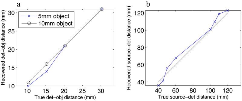
(a) Object location linearity of the depth of the object with respect to the detection plane. (b) Object location linearity of both the depth of the object with respect to the detection plane summed with distance with respect to the source plane.
The benefit of the technique developed in this study compared to previous developments with XLT is three-fold: increased temporal resolution is possible because of the optical read-out of two-dimensions, which eliminates X-ray encoding in those dimensions; lower dose is possible because of the decreased X-ray excitation; most importantly, this technique is suitable for geometries where full angular X-ray encoding is not possible. Therefore, this technique enables XLT to be used for surgeries such as breast lumpectomy; we foresee applications such as this to be one of the most important future applications in imaging. In breast lumpectomy, a full-angular encoding with X-ray is not desirable because deep critical structures are irradiated. By instead implementing a limited-angle technique, only the breast may be irradiated. For lumpectomy, this technique would be desirable to verify the position of the lesions in the surgical supine position, and to visualize remaining disease after resection.
In comparing this technique to other image-guided surgical modalities such as FMT, the advantages of LAXLT are clear. LAXLT was able to resolve 4mm objects at detector-object depths greater than 4.5cm, compared to FMT which is limited in to about 1cm in resolving object dimensions[18]. The most impressive aspect indicated by these results is the reduction in the blurring of the object with respect to depth; this highlights the advantage of incorporating the X-ray excitation, which due to its relatively insignificant scatter at these depths, can pinpoint the depth of the object with respect to the optical depth dimension. The optical read-out is then used to determine the other dimensions. Since the depth is known to high accuracy (shown in Figure 4), the diffuse algorithm properly models the diffuse nature of the light, and significantly reduces object blurring, as presented in Figure 5. Thus, with LAXLT, dose and imaging time are reduced significantly compared to XLT.
It is intuitive that the resolution will be limited by the width of the X-ray beam, at shallower depths. At deeper depths, the scatter of the X-ray beam should be taken into account. In this study, a 1mm collimated X-ray beam was able to successfully visualize a 2mm object up to 2cm, and a 4mm object up to 4.5cm. Higher resolution should be attained with a narrower beam; we are currently investigating this effect. The ability to resolve an object at depth is instead limited by dose.
Although this study was adapted to geometries best suitable to tumor resection, it should be noted that the algorithm presented in this work is generalizable to any geometry; it is especially useful for sparse-angle geometries. An additional use for this technique would be for intraoperative probes, where simple coregistration (assuming the catheter is radio-opaque) between the X-ray source and the optical detection catheter could provide assessment of molecular status at a remote location.
An increase in dose to potentially healthy tissue is one disadvantage of this technique. Although we calculated that the maximum dose to the phantom was 33.4 cGy, this dose will be reduced to 6cGy with a more favorable optical setup where the camera is closer to the object. This dose may be reduced further with a contact optical setup. Still, this dose may preclude its use in a screening setting, especially due to the increasing awareness of increasing radiation exposure in medicine[34]. However, post-surgical radiation therapy is commonly prescribed as a means to destroy cancer cells that may not have been removed around the margin [35, 36]. In Accelerated Partial Breast Irradiation, 5–20 Gy of radiation is given to the resected cavity in 1–5 fractions, to reduce the morbidity of whole breast radiation therapy [37]. In this context, LAXLT may have great utility to identify larger regions that may have been missed during surgery, and may require subsequent surgical investigation. Its sensitivity at this dose might enable the identification of micro-disease, or a very low concentration to be injected.
The other disadvantage of this technique is its use of nanoparticles. Although we have demonstrated low-toxicity of our nanoparticles in cells, nanoparticles will have different effects in a living system. This topic is beyond the scope of this paper, but it is important to recognize that cancer nanotechnology is a major venture in the National Cancer Institute, and this technique will benefit from the knowledge gained from this program.
5. Conclusions
Limited Angle X-ray Luminescence Tomography has been developed as a means to image molecular deeper than is available with Fluorescence Molecular Tomography. A reconstruction algorithm, based on a hybrid X-ray excitation/diffuse optical emission model, was tested in a numerical and experimental phantom that had dimensions similar to the human breast. It was found that objects as small as 2mm in diameter could be resolved at depths of up to 4–5cm. It was shown that the depth of the object with respect to the X-ray source position had little effect on object recovery in this volume. It was then demonstrated experimentally that both a 5mm and 10mm object could be resolved at depths of at least 3cm – these results agreed with the numerical phantom results, thus validating the simulation. If the challenges to engineering biocompatible phosphors can be resolved, LAXLT may have utility in surgical applications where small lesions must be imaged at depth of a few centimeters, such as during breast lumpectomy surgery.
Acknowledgments
The authors gratefully acknowledge the Department of Defense Breast Cancer Postdoctoral Fellowships W81XWH-10-1-0506 (CMC), W81XWH-11-1-0070 (GP), and W81XWH-11-1-0087 (CS), the National Institutes of Health ICMIC P50CA114747, the Center for Biomedical Imaging at Stanford, and the Friends for Early Breast Cancer Detection, for funding.
References
- 1.Gibson GR, Lesnikoski BA, Yoo J, Mott LA, Cady B, Barth RJ., Jr A comparison of ink-directed and traditional whole-cavity re-excision for breast lumpectomy specimens with positive margins. Ann Surg Oncol. 2001;8(9):693–704. doi: 10.1007/s10434-001-0693-1. [DOI] [PubMed] [Google Scholar]
- 2.Fortin A, Larochelle M, Laverdière J, Lavertu S, Tremblay D. Local failure is responsible for the decrease in survival for patients with breast cancer treated with conservative surgery and postoperative radiotherapy. J Clin Oncol. 1999;17(1):101–9. doi: 10.1200/JCO.1999.17.1.101. [DOI] [PubMed] [Google Scholar]
- 3.Weissleder R, Pittet MJ. Imaging in the era of molecular oncology. Nature. 2008;452(7187):580–9. doi: 10.1038/nature06917. [DOI] [PMC free article] [PubMed] [Google Scholar]
- 4.Tanaka E, Choi HS, Fujii H, Bawendi MG, Frangioni JV. Image-guided oncologic surgery using invisible light: completed pre-clinical development for sentinel lymph node mapping. Ann Surg Oncol. 2006;13(12):1671–81. doi: 10.1245/s10434-006-9194-6. [DOI] [PMC free article] [PubMed] [Google Scholar]
- 5.Alex JC, Krag DN. Gamma-probe guided localization of lymph nodes. Surg Oncol. 1993;2(3):137–43. doi: 10.1016/0960-7404(93)90001-f. [DOI] [PubMed] [Google Scholar]
- 6.Stummer W, Reulen H-J, Meinel T, Pichlmeier U, Schumacher W, Tonn J-C, Rohde V, Oppel F, Turowski B, Woiciechowsky C, Franz K, Pietsch T ALA-Glioma Study Group. Extent of resection and survival in glioblastoma multiforme: identification of and adjustment for bias. Neurosurgery. 2008;62(3):564–76. doi: 10.1227/01.neu.0000317304.31579.17. discussion 564–76. [DOI] [PubMed] [Google Scholar]
- 7.Torzilli G, Takayama T, Hui AM, Kubota K, Harihara Y, Makuuchi M. A new technical aspect of ultrasound-guided liver surgery. Am J Surg. 1999;178(4):341–3. doi: 10.1016/s0002-9610(99)00193-2. [DOI] [PubMed] [Google Scholar]
- 8.Carpenter C, Sun C, Pratx G, Rao R, Xing L. Hybrid X-ray/Optical Luminescence Imaging; Characterization of Experimental Conditions. Medical Physics. 2010;37:4011. doi: 10.1118/1.3457332. [DOI] [PMC free article] [PubMed] [Google Scholar]
- 9.Pratx G, Carpenter C, Sun C, Xing L. X-Ray Luminescence Computed Tomography via Selective Excitation: A Feasibility Study. IEEE Trans Med Imaging. 2010;29(12):1992–1999. doi: 10.1109/TMI.2010.2055883. [DOI] [PMC free article] [PubMed] [Google Scholar]
- 10.Pratx G, Carpenter C, Sun C, Ravilisetty P, Xing L. Tomographic Molecular Imaging using X-Ray-Excitable Nanoparticles. Optics Letters. 2010;35(20):3345–3347. doi: 10.1364/OL.35.003345. [DOI] [PMC free article] [PubMed] [Google Scholar]
- 11.Chen W. Nanoparticle fluorescence based technology for biological applications. J Nanosci Nanotechnol. 2008;8(3):1019–51. doi: 10.1166/jnn.2008.301. [DOI] [PubMed] [Google Scholar]
- 12.Sun C, Carpenter C, Pratx G, Xing L. Facile Synthesis of Amine-Functionalized Eu3+-Doped La(OH)3 Nanophosphors for Bioimaging. Nanoscale Research Letters. 2010 doi: 10.1007/s11671-010-9768-x. [DOI] [PMC free article] [PubMed] [Google Scholar]
- 13.Sokolov K, Follen M, Aaron J, Pavlova I, Malpica A, Lotan R, Richards-Kortum R. Real-time vital optical imaging of precancer using anti-epidermal growth factor receptor antibodies conjugated to gold nanoparticles. Cancer Res. 2003;63(9):1999–2004. [PubMed] [Google Scholar]
- 14.Haubner R, Wester HJ, Weber WA, Mang C, Ziegler SI, Goodman SL, Senekowitsch-Schmidtke R, Kessler H, Schwaiger M. Noninvasive imaging of alpha(v)beta3 integrin expression using 18F-labeled RGD-containing glycopeptide and positron emission tomography. Cancer Res. 2001;61(5):1781–5. [PubMed] [Google Scholar]
- 15.Chen X, Conti PS, Moats RA. In vivo near-infrared fluorescence imaging of integrin alphavbeta3 in brain tumor xenografts. Cancer Res. 2004;64(21):8009–14. doi: 10.1158/0008-5472.CAN-04-1956. [DOI] [PubMed] [Google Scholar]
- 16.Barrett HH. Limited-angle tomography for the nineties.[comment] Journal of Nuclear Medicine. 1990;31(10):1688–92. [PubMed] [Google Scholar]
- 17.Roberts DW, Valdés PA, Harris BT, Fontaine KM, Hartov A, Fan X, Ji S, Lollis SS, Pogue BW, Leblond F, Tosteson TD, Wilson BC, Paulsen KD. Coregistered fluorescence-enhanced tumor resection of malignant glioma: relationships between delta-aminolevulinic acid-induced protoporphyrin IX fluorescence, magnetic resonance imaging enhancement, and neuropathological parameters. J Neurosurg. 2010 doi: 10.3171/2010.2.JNS091322. [DOI] [PMC free article] [PubMed] [Google Scholar]
- 18.Kepshire DS, Davis SC, Dehghani H, Paulsen KD, Pogue BW. Subsurface diffuse optical tomography can localize absorber and fluorescent objects but recovered image sensitivity is nonlinear with depth. Appl Opt. 2007;46(10):1669–78. doi: 10.1364/ao.46.001669. [DOI] [PubMed] [Google Scholar]
- 19.O’Leary MA, Boas DA, Chance B, Yodh AG. Experimental images of heterogeneous turbid media by frequency-domain diffusing-photon tomography. Opt Lett. 1995;20(5):426–428. doi: 10.1364/ol.20.000426. [DOI] [PubMed] [Google Scholar]
- 20.Ma CM, Coffey CW, DeWerd LA, Liu C, Nath R, Seltzer SM, Seuntjens JP American Association of Physicists in Medicine. AAPM protocol for 40–300 kV x-ray beam dosimetry in radiotherapy and radiobiology. Med Phys. 2001;28(6):868–93. doi: 10.1118/1.1374247. [DOI] [PubMed] [Google Scholar]
- 21.Munck af Rosenschöld P, Nilsson P, Knöös T. Kilovoltage x-ray dosimetry--an experimental comparison between different dosimetry protocols. Phys Med Biol. 2008;53(16):4431–42. doi: 10.1088/0031-9155/53/16/014. [DOI] [PubMed] [Google Scholar]
- 22.Verhaegen F, Nahum AE, Van de Putte S, Namito Y. Monte Carlo modelling of radiotherapy kV x-ray units. Phys Med Biol. 1999;44(7):1767–89. doi: 10.1088/0031-9155/44/7/315. [DOI] [PubMed] [Google Scholar]
- 23.Arridge SR, Schweiger M, Hiraoka M, Delpy DT. A Finite-Element Approach for Modeling Photon Transport in Tissue. Medical Physics. 1993;20(2):299–309. doi: 10.1118/1.597069. [DOI] [PubMed] [Google Scholar]
- 24.Cheong WF, Prahl SA, Welch AJ. A review of the optical properties of biological tissues. IEEE J of Quant Electr. 1990;26(12):2166–2185. [Google Scholar]
- 25.Schweiger M, Arridge SR, Hiraoka M, Delpy DT. The finite element method for the porpagation of light in scattering media: Boundary and source conditions. Medical Physics. 1995;22(11):1779–1792. doi: 10.1118/1.597634. [DOI] [PubMed] [Google Scholar]
- 26.Aronson R. Boundary-conditions for diffusion of light. J Opt Soc Am A. 1995;12(11):2532–2539. doi: 10.1364/josaa.12.002532. [DOI] [PubMed] [Google Scholar]
- 27.Jiang HB. Frequency-domain fluorescent diffusion tomography: a finite- element-based algorithm and simulations. Applied Optics. 1998;37(22):5337–5343. doi: 10.1364/ao.37.005337. [DOI] [PubMed] [Google Scholar]
- 28.Marquardt DW. An Algorithm for Least-Squares Estimation of Nonlinear Parameters. Journal of the Society for Industrial and Applied Mathematics. 1963;11(2):431–441. [Google Scholar]
- 29.Kandarakis I, Cavouras D, Panayiotakis G, Agelis T, Nomicos C, Giakoumakis G. X-ray induced luminescence and spatial resolution of La2O2S:Tb phosphor screens. Phys Med Biol. 1996;41(2):297–307. doi: 10.1088/0031-9155/41/2/007. [DOI] [PubMed] [Google Scholar]
- 30.Peters VG, Wyman DR, Patterson MS, Frank GL. Optical properties of normal and diseased human breast tissues in the visible and near infrared. Phys Med Biol. 1990;35:1317–1334. doi: 10.1088/0031-9155/35/9/010. [DOI] [PubMed] [Google Scholar]
- 31.Gregorie HB, Jr, Horger EO, Ward JL, Green JF, Richards T, Robertson HC, Jr, Stevenson TB. Hematoporphyrin-derivative fluorescence in malignant neoplasms. Ann Surg. 1968;167(6):820–8. doi: 10.1097/00000658-196806000-00002. [DOI] [PMC free article] [PubMed] [Google Scholar]
- 32.Stummer W, Novotny A, Stepp H, Goetz C, Bise K, Reulen HJ. Fluorescence-guided resection of glioblastoma multiforme by using 5-aminolevulinic acid--induced porphyrins: a prospective study in 52 consecutive patients. J Neurosurg. 2000;93:1003–1013. doi: 10.3171/jns.2000.93.6.1003. [DOI] [PubMed] [Google Scholar]
- 33.Boyette LB, Reardon MA, Mirelman AJ, Kirkley TD, Lysiak JJ, Tuttle JB, Steers WD. Fiberoptic imaging of cavernous nerves in vivo. J Urol. 2007;178(6):2694–700. doi: 10.1016/j.juro.2007.07.124. [DOI] [PubMed] [Google Scholar]
- 34.Caoili EM, Cohan RH, Ellis JH, Dillman J, Schipper MJ, Francis IR. Medical decision making regarding computed tomographic radiation dose and associated risk: the patient’s perspective. Arch Intern Med. 2009;169(11):1069–71. doi: 10.1001/archinternmed.2009.139. [DOI] [PubMed] [Google Scholar]
- 35.Dirbas FM. Accelerated partial breast irradiation: where do we stand? J Natl Compr Canc Netw. 2009;7(2):215–25. doi: 10.6004/jnccn.2009.0015. [DOI] [PubMed] [Google Scholar]
- 36.Munshi A. External hypofractionated whole-breast radiotherapy: now where does accelerated partial breast irradiation stand? J Cancer Res Ther. 2007;3(4):231–5. doi: 10.4103/0973-1482.38999. [DOI] [PubMed] [Google Scholar]
- 37.Ross G. Accelerated partial breast irradiation: technically feasible but who will benefit? Breast Cancer Res. 2005;7(3):110–2. doi: 10.1186/bcr1016. [DOI] [PMC free article] [PubMed] [Google Scholar]


