Abstract
The ex vivo and in vivo imaging, and quantitative characterization of the degradation of surgical sutures (∼500 μm diameter) up to ∼1cm depth is demonstrated using a custom dark-field photo-acoustic microscope (PAM). A practical algorithm is developed to accurately measure the suture diameter during the degradation process. The results from tissue simulating phantoms and mice are compared to ex vivo measurements with an optical microscope demonstrating that PAM has a great deal of potential to characterize the degradation process of surgical sutures. The implications of this work for industrial applications are discussed.
OCIS codes: (110.5120) Photoacoustic imaging, (170.0170) Medical optics and biotechnology
1. Introduction
Surgical sutures are commonly used for soft tissue approximation, i.e. to close deep wounds by suturing different tissue layers that have been compromised before. The suture thread can be made from numerous materials. Modern sutures are synthetic and can be divided into absorbable (naturally biodegradable in the body) or non-absorbable sutures [1]. Absorbable sutures play a crucial role in some specific major surgical procedures. Their primary duty is to support the tissue for a defined period of time during wound healing and to degrade after its functionality is not needed anymore in order to avoid a chronic foreign body reaction towards the implanted material [2]. Since different types of tissues (mucosa, fascia, tendons and others) require a specific time to heal, it is of great importance to have detailed knowledge of the degradation profile of the sutures over time. Key questions include the strength and mass loss of the sutures as well as their relationship to the surrounding tissue physiology, i.e. their biocompatibility and tissue reaction.
In order to gain regulatory approval for a new absorbable suture material, the manufacturer has to demonstrate that the degradation profile is reproducible under in vivo conditions and that the degrading suture does not elicit any harmful tissue reaction. Typically this is done using invasive testing with animals which involves sacrificing the animals at certain time points, harvesting the implantation sites and performing a histopathological examination of the harvested tissue. An imaging technique that is non-invasive and is capable of measuring the suture degradation in vivo by quantifying its diameter over time and the local tissue physiology would be of great value in the development process of new sutures and other absorbable medical devices. The tissue physiology and suture degradation could be studied directly under “living conditions” and not in explanted tissue which has to undergo several conditioning steps before the actual histopathological examination which may change its status. Furthermore, fewer animals would be sacrificed for a non-invasive study.
Absorbable sutures for tissue approximation are manufactured with different standard diameters. In this work we focus on sutures of ∼500 μm diameter (size “USP 1” according to United States Pharmacopeia) which are widely used. When inserted in tissue, they degrade down to 100 μm diameter before they get completely reabsorbed. Therefore, in order to carry out noninvasive, in vivo measurements, a high resolution imaging technique (∼50 μm) with a good penetration depth (∼1 cm) is required.
One of the currently available imaging techniques is micro X-ray computed tomography (Micro-CT). However, sutures and similar implants do not give sufficient contrast in the CT images. Another possibility would be magnetic-resonance imaging systems, however, their standard spatial resolution and contrast may also not reach the specific needs of this task. For both methods, it is possible to improve the measurable contrast by adding contrast enhancing agents to the matrix of these synthetic polymers (polypropylene, polyester) [3,4], which makes the use of these techniques quite expensive and relatively complex.
On the other hand, ultrasound based imaging methods appear as a suitable alternative for this imaging task due to their high resolution, portability of the equipment and safety [5]. Although it is possible to visualize sutures inside human bodies with ultrasound-based techniques (UT) [6], it is not demonstrated that the diameter of the suture is accurately determined. This is because the images from UT techniques tend to have low contrast between the healthy muscles, injured muscles and the sutures. For this reason, contrast shells or dyes are applied on the sutures in order to enhance the contrast of the images [7]. However, this is also non-decisive and the contrast drastically decays in time as the suture degrades, making longitudinal imaging difficult since the coating disappears in first place.
Photoacoustic imaging (PAI) is an emerging alternative imaging method based on the photoacoustic effect which is produced when biological tissue is irradiated with a short light pulse leading to thermo-elastic expansion that induces the emission of an acoustic wave [8–12]. The distribution of the absorbed light energy deposition can be obtained with ultrasonic (in deep, i.e. ∼1 cm tissues) or optical (in shallow, i.e. ∼1 mm) spatial resolution using appropriate ultrasound detectors and some data processing. Since the local light absorption is due to the presence of absorbers, the results reflect the distribution of the absorbers. In fact, different kind of highly absorbing synthetic threads are commonly used to measure the resolution of the different PAI systems [13, 14]. Here we hypothesize that most medical sutures used in surgery produce different photoacoustic signals than the surrounding medium due to their different absorption properties and, therefore, PAI can be used to image embedded sutures.
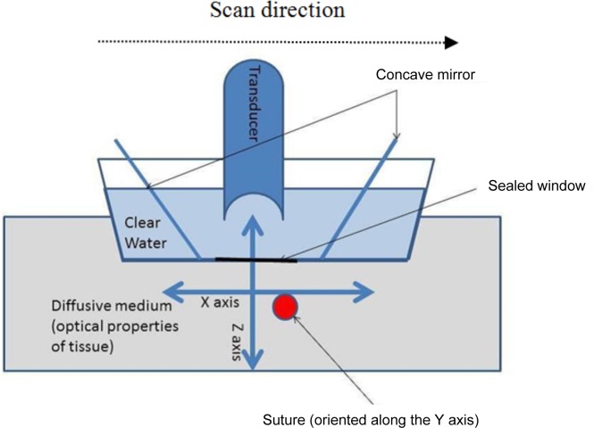
Among the different PAI systems, raster scan dark-field photoacustic microscopy [15–18] can be envisioned as a tool for this task since it is able to image objects deep in tissue (>10 mm depth) with a high axial and lateral resolution (few tenths of microns depending on the properties of the ultrasonic detector and imaged depth). In fact, it has previously been used to detect foreign bodies in tissues [18]. Dark-field PAM and most other raster scan systems, utilize a spherically focused transducer directed toward the subject to be imaged. The tissue is illuminated by a ring of light and the ultrasound detector is placed at the centre of the field (see Fig. 1). This illumination scheme leads to a pseudo-confocal condition between the excitation light and the transducer, while avoiding the strong photoacoustic signal that is generated due to the melanin of the skin surface, hence emerging the term “dark-field”. The transducer and the illumination system are attached to a scanning head that performs a raster scan on the x–y plane from which several “amplitude mode” lines (“A lines”) are obtained in depth direction, i.e. z direction, that allows us to put together several two-dimensional (2D) planes or “brightness mode” lines (“B-lines”) yielding a 3D image [16, 17].
Fig. 1.
Schematic representation of the acquisition of one B-scan.
In this paper we have investigated the performance of a custom made photoacoustic system for imaging degradable sutures. Specifically, we have measured its ability to determine the diameter of the sutures while embedded in turbid media by introducing a simple approach which takes advantage of the higher axial resolution. We have validated the approach using numerical simulations, with phantom experiments and ex vivo in mice, against ex vivo measurements by an optical microscope.
2. Materials and methods
2.1. Numerical simulations
We have simulated the photoacustic signal generated from a cylindrical solid mimicking the shape of a medical suture using the software package K-Wave [19]. Each cylinder had a different diameter; 100, 200, 300, 400, 450, 500, 600 and 700 μm. In order to a avoid memory handling issues, the simulations were run in two dimensions, therefore, the generated photoacoustic signals are equivalent to the ones generated by infinite long cylinders.
Each suture was situated in the focal point of a circularly focused detector with a focal distance of 6.7 mm and a numerical aperture of 0.44. The grid spacing of the simulation was set as 4 μm allowing us to simulate ultrasound frequencies up to 258 MHz.
The photoacoustic signal generated from a solid cylinder has been studied by different authors [20–23]. The simulated results depend on the ultrasound transducer properties in particular its instrument response function. In our case, we have used the manufacturer specified response in the frequency domain with a peak response centred at 20 MHz with a Gaussian bandwidth of 80%. This is applied to generate the simulated acoustic signal. The diameter of the sutures were obtained by computing the time between the first positive peak and the second negative peak (see below) and multiplying by the speed of sound in the suture material taken as 1550 m/s.
In general terms, a 3D simulation with a spherical focused transducer is needed. Here we stick to the 2D simulation for simplicity and efficiency since the results will be shown to be in qualitative agreement with the experiments. This could be addressed in the future.
2.2. Laboratory PAM system
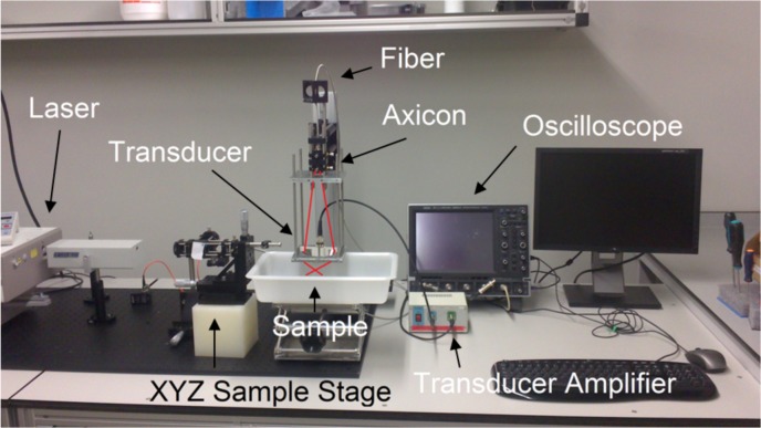
The imaging system we have used is based on the one introduced by [17] and further details are available in Aguirre et al [24]. Briefly, a tunable near-infrared Ti:sapphire laser (LT-2211A, LOTIS TII, Minsk, Belarus) pumped by a Q-switched Nd:YAG laser (LS-2137/2, LOTIS TII, Minsk, Belarus) is used to generate the photoacoustic excitation. The laser pulse width is ∼10 ns, and, for our experiments, we have tuned it at 700 nm with a repetition frequency of 10 Hz. The light is delivered through an optical fiber to the PAM scanner head. Photograph of the system is shown in Fig. 2.
Fig. 2.
Picture of the PAM scanning head. The trace of the laser is shown in red.
To detect the generated photoacoustic waves a 20 MHz spherically focused ultrasonic transducer with ∼2.7 mm depth of focus (V317, Olympus, Essex, UK) was used allowing a lateral resolution of 120 μm and an axial resolution of 50 μm. For our experiments, the scanning head is placed in a water container with a window sealed with an acoustically and optically transparent plastic membrane.
2.3. Measuring the diameter of the sutures from the experimental data
2.3.1. The phantom experiments
Twelve Monomax long term absorbable monofilament sutures (size USP 1, B.Braun Surgical, S.A., Rubí, Barcelona, Spain) made from the polyester “poly-4-hydroxybutyrate” and dyed violet with “D&C Violet No. 2” (1-hydroxy-4-[(4-methylphenyl)amino]-9,10-anthracenedione) were split in two groups of six sutures each. The first group (Group 1) did not undergo a degradation process and acted as the control group. The second group (Group 2) underwent a degradation process.
In general, absorbable sutures first lose their tensile strength while retaining a large portion of their mass and the actual absorption of the suture mass happens sometime after the suture has lost their functionality in terms of tensile strength. Two basic mechanisms of hydrolytic degradation may apply for an absorbable suture material; surface hydrolysis and bulk hydrolysis. The prevalent mechanisms depend mainly on the water diffusion coefficient and the equilibrium water sorption of the polymer. In the case of Monomax (poly-4-hydroxybutyrate) it was observed during in vivo and in vitro studies that the absorption of the fibre is accompanied by a steady loss of the diameter of the Monomax fiber, which might indicate that the surface hydrolysis mechanism is predominant for this type of suture, though molecular weight analysis of the fiber remnants shows that also bulk hydrolysis is present [25, 26].
Since the true in vivo degradation of this class of sutures and the absorption of the mass of the Monomax suture of size USP 1 can take more than thirty-six months, we have used an accelerated degradation process. To achieve this, the sutures of the second group were immersed for twelve weeks in an acidic bath of 3 molar hydrochloric acid (3M HCl) at 37°C and under continuous agitation. The acidic bath accelerates the degradation process (acidic catalysis) of the sutures, which in this case, degrade due to the hydrolytic cleavage of the ester bonds of their polyester base material.
For each imaging session, the sutures were removed from the bath and each group was imaged using PAM while being immersed in a solution of Lipofundina(B.Braun Melsungen AG, Melsungen, Germany) and distilled water that mimics the acoustic impedance and the optical properties of tissue achieving optical values of μ′s ≈10 cm−1 and μa ≈0.0057 cm−1 at 700 nm. The optical properties of the phantom were confirmed by time resolved spectroscopy [27]. For most of the imaging sessions, the sutures were placed three millimeters deep in the phantom unless otherwise stated as shown in Fig. 3.
Fig. 3.

(a) A suture and the holder before placement in the PAM system and (b) the phantom and the suture before adding Lipofundina solution.
The PAM imaging session consisted in a single B-scan with a scan step of 50 μm and a total length of 6 mm in the direction perpendicular to the suture (see Fig. 1). By doing this, a 2D PAM (x–z plane) image was obtained corresponding to an axial slice of the imaged sutures. After the photoacoustic imaging session, the sutures where imaged in vitro with a conventional optical microscope (“gold standard”) using a 10x objective. Great care was taken to assure that the sutures did not dry out before measuring the diameter under the microscope since the thread can become ∼50 μm thinner when dry. The diameter of the sutures was estimated from both techniques and then compared.
2.3.2. Estimation of the diameter of the sutures from the PAM raw images and the calibration constant
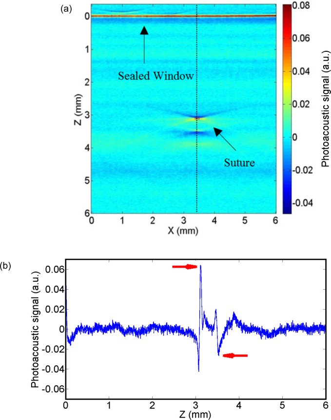
To obtain the diameter of the sutures from the acquired PAM images, we have measured the peak-to-peak distance (i.e. Δt·vs where Δt is the distance in time and vs is the speed of sound in water) from the A-line obtained from the suture when the centre of the suture overlaps the focal point of the transducer. As done with the simulations, the diameter of the sutures was obtained by computing the time between the first positive peak and the second negative peak. As we show in Section 3.2., the peak-to-peak measurement does not provide an absolute value of the diameter of the suture and therefore, a calibration constant, C, must be calculated. This constant is subtracted from all the measured peak-to-peak distances. C is calculated following this expression:
| (1) |
Here Dreal is the diameter of the suture as measured in vitro using an optical microscope and DPAM is the diameter of the suture as measured from the photoacoustic signal from the peak-to-peak distance. From all the twelve measured sutures, the six non-degraded sutures were selected, and C was calculated as an average. Another set of (data not shown) sutures prepared at a different degradation time point were also measured and it was confirmed that C is applicable.
2.4. Quantification of the depth dependence of the results
The measured A-lines from the sutures are modified due to the spherical shape of the transducer when they are situated away from its focal point. Specifically the transducer acts like a low pass filter [28, 29]. Therefore, we had tested the performance of the proposed peak-to-peak measurements as a function of depth, using a single suture that was immersed in the liquid phantom (see Section 2.3.1). The suture was attached to a linear stage which allowed us to place the suture at nine different depths ranging from 2 mm to 9 mm. For each depth a B-scan was performed with a step of 50 μm and a total length of 6 mm in the direction perpendicular to the suture in the same fashion as described in Section 2.3.1. We note that when the suture is imaged below the focal zone of the transducer it appears with a well-known semicircular shape in the 2D images. This effect is more evident the further the suture is away from the focal zone, and is well explained and known in the literature [13]. Various modelling approaches can be utilized to account for these effects which are beyond the scope of this paper [24, 28, 30]. In this case, for each depth position, three A-lines were selected to make the peak-to-peak measurements corresponding to the part of the semicircular shape closer the surface. The diameter was taken as the average of the three peak-to-peak distances.
2.5. In vivo mouse experiments
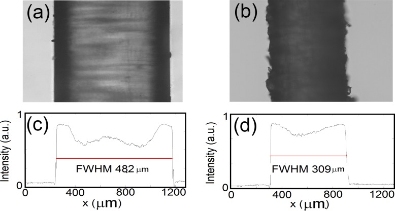
All animal studies were approved by the animal ethics committee of Bellvitge Institute for Biomedical Research (IDIBELL, Barcelona, Spain). Two sutures of 309 μm and 482 μm diameter were inserted into the leg of two different euthanized athymic male mice about one millimetre below the skin. The diameters of the sutures were measured as the full-width-half-maximum of the profile of the image obtained in the direction perpendicular to the suture with an optical microscope (Figs. 5(c) and 5(d)). For each suture, three different B-scans of length 5 mm and scanning step 100 μm were carried out. The distance between each B-scan in the x–y plane was 1 mm. For each B-scan the diameter of the suture was estimated measuring the peak-to-peak distances in the same manner as was described in Section 2.3.2. Therefore for each suture, its diameter was measured in three different parts of the leg of the corresponding mouse. The height of the transducer was adjusted to leave the suture close to its focal point to ensure that the suture overlaps the focal point of the transducer.
Fig. 5.
An optical microscope image of a non-degraded suture corresponding to the Group 1 (a) and an optical microscope image of a degraded suture corresponding to the Group 2 (b). The dashed lines represent the profiles for which the full-width-half-maximum is calculated (c and d).
In order to distinguish the suture from the surrounding tissue we did the following: part of the thread was in the water outside the mouse and part was inside the mouse. Several extra B-scans were performed covering areas inside the mouse and outside the mouse. Following the different slices, we could clearly see the continuity of the suture out of the water and inside the mouse.
3. Results
3.1. Simulations
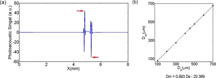
The result for a simulated diameter of the suture of 500 μm is shown in Fig. 4(a). The diameter of the suture is measured by taking the distance between the two highlighted peaks. We show the relationship between the diameter of the simulated sutures and the values obtained from the peak-to-peak distances for different diameter cylinders in Fig. 4(b). There is a strong linear relationship between the simulated diameters and the values obtained from the simulated photoacoustic signals (see Fig. 4(b)). The peak-to-peak distance gives a good relative estimation rather than absolute, therefore, a calibration constant must be introduced in order to retrieve absolute values which is because of a variety of factors that change the location of these peaks. For the rest of this work, the calibration factor is calculated from experimental data, as previously explained.
Fig. 4.
(a) Numerically simulated photoacoustic signal generated by a solid cylinder. The diameter of the cylinder was estimated from the peak-to-peak equivalent distance (Δt·vs) from the peaks pointed with the red arrows. (b) Plot of the diameter measured from the simulated photoacoustics signals (Dm) vs the simulated diameter of the sutures (Ds). After doing a linear regression, the goodness of the fit was 0,99.
3.2. Phantom and euthanized mouse experiment
The in vitro optical microscope images obtained from one control suture and one degraded suture are shown in Fig. 5. As commented before, the diameter of the sutures is measured with the optical microscope. The measured diameter of the sutures presented in Fig. 5 are 482.04 μm and 309.92 μm respectively.
In Fig. 6(a), the raw 2D image corresponding to a complete B-scan is shown. The photoacoustic signal obtained from the sutures is quadri-phasic, two maximums and two minimums as shown in Fig. 6(b). The small discrepancies with the simulated signals (see Fig. 4(a)) are due to the combination of different effects such as the non-perfect simulated frequency response dependency of the transducer and the non-homogeneous light absorption inside the suture [31]. The method presented here relies on B-scans for measuring the suture diameter. In some experiments (data not shown), different B- scans scans were tested across the length of the suture where less than 4% variation in the measured diameter was observed. PAM system allows for a 2D scan on the sample surface and the diameter can be calculated for each position along the suture, and, even, for multiple overlapping sutures.
Fig. 6.
(a) A raw 2D image corresponding to one B-scan of a suture immersed in a turbid medium. The dashed line corresponds to the A-line from which the diameter is measured. (b) A-line corresponding to the dashed line. The peaks from which the peak-to-peak to distance is measured are pointed by the red arrows.
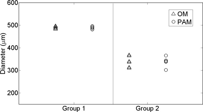
As shown in Table 1 and Fig. 7, the measured diameter from the photoacoustic images is in excellent agreement with the diameter obtained from the optical microscope.
Table 1.
Mean values and the standard deviation of the measured diameters of the sutures of each group obtained with each technique.
| Photoacoustic microscopy | Optical microscope | |
|---|---|---|
| Diameter, Group 1 | 488.7 ± 6.3 μm | 488.7 ± 5.4 μm |
| Diameter, Group 2 | 337.9 ± 20.6 μm | 338.3 ± 24.4 μm |
Fig. 7.
Estimated diameters of all the sutures corresponding to the phantom experiment. The triangles represent the measures obtained from the optical microscope (OM) whereas the circles correspond to the photoacoustic microscope (PAM) measures. The non-degraded sutures are represented in Group 1 whereas the degraded are in Group 2. The suture is assumed to be cylindrical and then, the diameters measured in the axial cross-section (with PAM) or the lateral view (with OM) are equivalent.
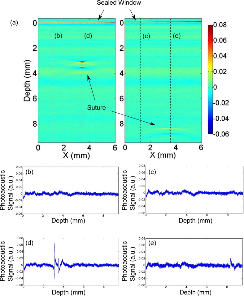
Moreover, by increasing the depth of the suture inside the turbid medium we have quantified the depth dependence of the results. We were able to image the embedded suture down to nine millimetres (9 mm) below the surface of the sealed window in turbid media as shown in Fig. 8. Quadriphasic signals that are due to the presence of a suture are distinguishable from the background noise and artifacts in all cases. As shown in Fig. 9, the maximum difference in the estimated diameters was 44.4 μm, demonstrating that our approach is feasible at significant depths. We note that for a transducer with a given sensitivity and given light illumination power, the maximum depth achievable is determined by the tissue optical and acoustical properties.
Fig. 8.
(a) Two raw 2D images showing the photoacoustic signal (a.u.) from the suture at two depths; 3.3 mm below the surface and 8.4 mm below the surface; (b)–(c) plots of the A-line of the planes without suture and (d)–(e) plots of the A-line of the planes with the signal of the suture. Quadriphasic signals that are due to the presence of a suture are distinguishable from the background noise and artifacts.
Fig. 9.
Estimation of the diameter of the suture at different depths from the PAM images.
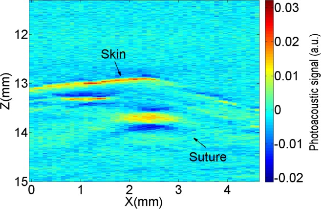
Furthermore, we are able to measure the radius of a suture fiber inside euthanized mice. As shown in Fig. 10, when imaging the sutures in tissue, several other absorbing objects (e.g. blood vessels) appear in the images, however, the suture can be clearly observed.
Fig. 10.
2D raw photoacoustic image corresponding to one B-Scan for one euthanized mouse.
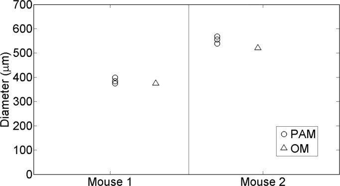
The measured diameter from the photoacoustic images are in agreement with diameter obtained from the ex vivo microscope measurement. The results are summarized in Fig. 11.
Fig. 11.
Estimated diameters of the all the sutures corresponding to the ex vivo mice experiments. The circles show the measures obtained from the photoacoustic microscope (PAM) whereas the triangles correspond to the optical microscope (OM) measures.
4. Discussion and conclusions
In this paper we have demonstrated that dark-field PAM is a promising tool for in vivo, noninvasive imaging and quantification of the degradation process of sutures placed deep in tissues. We have introduced a simple algorithm based on the location of specific peaks of the raw photoacoustic signal coming from the threads that takes advantage of the higher axial resolution characteristic of raster scan systems based on spherical transducers. We have validated this approach using realistic numerical simulations which took the transducer instrument response function into account. We are able to measure the diameter of the real sutures before and after degradation in tissue phantoms that mimic the optical properties and acoustic impedance of tissue at depths ranging from 2 mm to almost 10 mm. The algorithm was also able to provide accurate result for sutures inserted in euthanized mice. The measurements were in total agreement with the gold standard, in vitro, measurements with a conventional optical microscope.
The simulation results were qualitatively similar (Fig. 4(a) vs Fig. 6(b)) to those obtained experimentally. In order to make the simulations, we had to do some additional approximations about the velocity of sound and the density of a suture since this information is not yet available for these specific materials that are prepared under these conditions. The relationship between the density of the suture and velocity of sound in the suture and the relative height and location of the peaks is complex and we have simulated the suture with water-like values (velocity of sound of 1500 m/s and density as 1000 Kg/m3). In general for other structures, the specific velocity and density of the structure has to be known a priori. We expect that if the technique is taken up by the industry, this information could be obtained as part of the development process.
The response function of the ultrasound transducer is one of the main factors that affects both the experiments and simulations. We have carried out a large range of numerical simulations (data not shown) for different response functions and suture acoustic impedances. By calculating a specific calibration constant for every set of parameters, the peak-to-peak algorithm could be successfully applied.
As shown in the mouse image Fig. 10, the distinctions between the suture and the surrounding absorbers such as the blood vessels might be an issue. A potential solution for this problem is the utilization of the differences in the spectral profile of the sutures and the blood vessels. A multispectral photoacoustic measurement would then allow us to distinguish different components [9]. Multispectral measurements would further enable us to quantify the tissue physiology surrounding the sutures.
Model based reconstruction algorithms are quite suitable for the imaging problem addressed in this work [24, 28, 29]. We have recently shown one such algorithm developed in particular for sutures imaged with PAM that is practical to implement in a personal computer [24]. In order to apply these methods for routine use, several systematic errors due to the modelling approximations should be calibrated.
In Fig. 9, we demonstrate that the effect on the signal due to the spherical shape of the transducer does not affect the accuracy of the proposed algorithm. On the other hand, the attenuation of ultrasound signal is frequency dependent and the highest frequencies that carry information for high spatial resolution are more attenuated than the smallest frequencies [32]. Therefore, it is expected that the axial resolution of the detector degrades with depth since the higher frequencies will be eventually attenuated [33]. According to previous literature [34], for one centimeter depth the resolution limit of a photoaocustic system is ∼50 μm which in the range of the needs of the imaging problem addressed here. Further work will evaluate in detail the maximum depth achievable with the proposed method using tissue samples or phantoms that mimic the acoustic attenuation of tissue.
We also note that the PA signal from the sutures is dependent on the properties of the suture, for example, the coating materials and their light absorption properties. For the sutures used in this work, the degradation of the sutures did not lead to a significant worsening of the PA signal because Monomax is not coated, it is monofilament structured. This condition may not hold with other types of sutures with different coating materials and their properties during the degradation process. We also note that this problem holds for any imaging method whether it is the micro-CT or the MRI since the contrast depends on the materials that are used in the manufacturing of the sutures. PAM appears to be particularly interesting since this off-the-shelf product worked so well. Furthermore, one could speculate that once the utility of the technique is proven useful, the sutures can be custom engineered to produce good PA signals without altering their in vivo properties.
In summary, we believe that PAI technologies have a good potential for the medical device industry. Usually within the development and registration process of an absorbable suture material, the study of the in vivo degradation behaviour is done by animal testing. To do this, a group of animals must be euthanized at defined stages of the degradation process to obtain the tissue samples for the histopathologic evaluation. Therefore, a considerable amount of animals are needed to perform a longitudinal study which is not ideal from the point of view of animal welfare and economical aspects. Besides, with PAI, the suture is studied “as it is” in a living environment and does not need to be explanted, which might damage or alter the harvested suture and tissue samples. This work shows that PAM offers the possibility to measure the suture diameter in time with enough resolution and with a good penetration depth in vivo. Future tests in living animals are needed to demonstrate its utility for longitudinal studies on individual animals.
Acknowledgments
The authors would like to thank B.Braun Surgical, S.A., Fundació Cellex Barcelona, and the Spanish Ministerio de Economía y Competitividad (Photostroke) for their funding support. We acknowledge useful discussions with Dr Romain Quidant, Dr Jan Laufer, Dr Lihong Wang and Dr Konstantin Maslov as well as contributions by Dr Alexia Giannoula and Laura Hottin to the experimental set-up.
References and links
- 1.Patel K. A., Thomas E., “Sutures, ligatures and staples,” Surgery 23, 56–60 (2005). [Google Scholar]
- 2.Moreira M. E., Markovchik. V. J., “Wound management,” Emer. Med.Clin. N.Am 25, 873–899 (2007). [DOI] [PubMed] [Google Scholar]
- 3.Palma P., Riccetto C., Fraga R., Miaoka R., Prando A., “Dynamic evaluation of pelvic floor reconstructive surgery using radiopadue meshes and three-dimensional helical ct,” International Braz. J. Urol 36, 209–217 (2010). 10.1590/S1677-55382010000200012 [DOI] [PubMed] [Google Scholar]
- 4.Sandaite I., Claus F., Mullen A., De Ridder D., Depreset J., “Experimental mri-contrast imaging of suture and mesh materials with fe3o4 -containing polivinylidenefluoride polymers designed for pelvic floor surgery,” Neurourology and Urodynamics 30, 1114–1115 (2011). [Google Scholar]
- 5.Foster F. S., Pavlin C. J., Harasiewicz K. A., Christopher D. A., Turnbull D. H., “Advances in ultrasound biomicroscopy,” Ultrasound Med Biol 26, 1–27 (2000). 10.1016/S0301-5629(99)00096-4 [DOI] [PubMed] [Google Scholar]
- 6.Gilleard O., Silver D., Ahmad Z., Devaraj V., “The accuracy of ultrasound in evaluating closed flexor tendon ruptures,” Eur. J. Plast. Surg. 33, 71–74 (2010). [Google Scholar]
- 7.El-Sherif D. M., Wheatley M. A., “Development of a novel method for synthesis of a polymeric ultrasound contrast agent,” J. Biomed. Mater. Res. 66A, 347–355 (2003). 10.1002/jbm.a.10586 [DOI] [PubMed] [Google Scholar]
- 8.Wang L. V., Hu S., “Photoacoustic tomography: in vivo imaging from organelles to organs,” Science 335, 1458–1462 (2012). 10.1126/science.1216210 [DOI] [PMC free article] [PubMed] [Google Scholar]
- 9.Razansky D., Buehler A., Ntziachristos V., “Volumetric real-time multispectral optoacoustic tomography of biomarkers,” Nat Protoc 6, 1121–1129 (2011). 10.1038/nprot.2011.351 [DOI] [PubMed] [Google Scholar]
- 10.Ntziachristos V., “Going deeper than microscopy: the optical imaging frontier in biology,” Nat Methods 7, 603–614 (2010). 10.1038/nmeth.1483 [DOI] [PubMed] [Google Scholar]
- 11.Wang L. V., “Multiscale photoacoustic microscopy and computed tomography,” Nat Photonics 3, 503–509 (2009). 10.1038/nphoton.2009.157 [DOI] [PMC free article] [PubMed] [Google Scholar]
- 12.Zhang E. Z., Laufer J. G., Pedley R. B., Beard P. C., “In vivo high-resolution 3d photoacoustic imaging of superficial vascular anatomy,” Phys Med Biol 54, 1035–1046 (2009). 10.1088/0031-9155/54/4/014 [DOI] [PubMed] [Google Scholar]
- 13.Li M. L., Zhang H. E., Maslov K., Stoica G., Wang L. V., “Improved in vivo photoacoustic microscopy based on a virtual-detector concept,” Opt Lett 31, 474–476 (2006). 10.1364/OL.31.000474 [DOI] [PubMed] [Google Scholar]
- 14.Gateau J., Caballero M. A., Dima A., Ntziachristos V., “Three-dimensional optoacoustic tomography using a conventional ultrasound linear detector array: whole-body tomographic system for small animals,” Med Phys 40, 013302 (2013). 10.1118/1.4770292 [DOI] [PubMed] [Google Scholar]
- 15.Zhang H. F., Maslov K., Wang L. V., “In vivo imaging of subcutaneous structures using functional photoacoustic microscopy,” Nat Protoc 2, 797–804 (2007). 10.1038/nprot.2007.108 [DOI] [PubMed] [Google Scholar]
- 16.Zhang H. F., Maslov K., Li M. L., Stoica G., Wang L. V., “In vivo volumetric imaging of subcutaneous microvasculature by photoacoustic microscopy,” Opt Express 14, 9317–9323 (2006). 10.1364/OE.14.009317 [DOI] [PubMed] [Google Scholar]
- 17.Maslov K., Stoica G., Wang L. V., “In vivo dark-field reflection-mode photoacoustic microscopy,” Opt Lett 30, 625–627 (2005). 10.1364/OL.30.000625 [DOI] [PubMed] [Google Scholar]
- 18.Cai X., Kim C., Pramanik M., Wang L. V., “Photoacoustic tomography of foreign bodies in soft biological tissue,” Journal of Biomedical Optics 16, 046017 (2011). 10.1117/1.3569613 [DOI] [PMC free article] [PubMed] [Google Scholar]
- 19.Treeby B. E., Cox B. T., “k-wave: Matlab toolbox for the simulation and reconstruction of photoacoustic wave fields,” J Biomed Opt 15, 021314 (2010). 10.1117/1.3360308 [DOI] [PubMed] [Google Scholar]
- 20.Hoelen C. G., de Mul F. F., “A new theoretical approach to photoacoustic signal generation,” J Acoust Soc Am 106, 11 (1999). [Google Scholar]
- 21.Wang K., Su B., Brecht P., Oraevsky A., Anastasio M., “An imaging model incorporating ultrasonic transducer properties for three-dimensional optoacoustic tomography,” IEEE Trans Med Imaging 30, 203–214 (2012). 10.1109/TMI.2010.2072514 [DOI] [PMC free article] [PubMed] [Google Scholar]
- 22.Wang L., Biomedical Optics: Principles and Imaging (Wiley, Hoboken, New Jersey, 2007). [Google Scholar]
- 23.Queiros D., Dean-Ben X. L., Buehler A., Razansky D., Rosenthal A., Ntziachristos V., “Modeling the shape of cylindrically focused transducers in three-dimensional optoacoustic tomography,” J Biomed Opt 18, 76014 (2013). 10.1117/1.JBO.18.7.076014 [DOI] [PubMed] [Google Scholar]
- 24.Aguirre J., Giannoula A., Minagawa T., Funk L., Turon P., Durduran T., “A low memory cost model based reconstruction algorithm exploting translational symmetry for photoacoustic microscopy,” Biomed Opt Express 4, 2813 (2013). 10.1364/BOE.4.002813 [DOI] [PMC free article] [PubMed] [Google Scholar]
- 25.Reis R. L., Roman J. S., Biodegradable Systems in Tissue Engineering and Regenerative Medicine (CRC Press, 2004). 10.1201/9780203491232 [DOI] [Google Scholar]
- 26.Odermatt E. K., Funk L., Bargon R., Martin D. P., Rizk S., Williams S. F., “Monomax suture: A new long-term absorbable monofilament suture made from poly-4-hydroxybutyrate,” International Journal of Polymer Science 2012216137 (2012). 10.1155/2012/216137 [DOI] [Google Scholar]
- 27.Durduran T., Choe R., Baker W. B., Yodh A., “Diffuse optics for tissue monitoring and tomography,” Rep. Prog. Phys. 73, 076701 (2010). 10.1088/0034-4885/73/7/076701 [DOI] [PMC free article] [PubMed] [Google Scholar]
- 28.Rosenthal A., Ntziachristos V., Razansky D., “Model-based optoacoustic inversion with arbitrary-shape detectors,” Med Phys 38, 4285–4295 (2011). 10.1118/1.3589141 [DOI] [PubMed] [Google Scholar]
- 29.Araque Caballero M. A., Rosenthal A., Gateau J., Razansky D., Ntziachristos V., “Model-based optoacoustic imaging using focused detector scanning,” Opt Lett 37, 4080–4082 (2012). 10.1364/OL.37.004080 [DOI] [PubMed] [Google Scholar]
- 30.Paltauf G., Viator J. A., Prahl S. A., Jacques S. L., “Iterative reconstruction algorithm for optoacoustic imaging,” J Acoust Soc Am 112, 1536–1544 (2002). 10.1121/1.1501898 [DOI] [PubMed] [Google Scholar]
- 31.Rosenthal A., Ntziachristos V., Razansky D., “Optoacoustic methods for frequency calibration of ultrasonic sensors,” IEEE Trans Ultrason Ferroelectr Freq Control 58, 316–326 (2011). 10.1109/TUFFC.2011.1809 [DOI] [PubMed] [Google Scholar]
- 32.Dean-Ben X. L., Razansky D., Ntziachristos V., “The effects of acoustic attenuation in optoacoustic signals,” Physics in Medicine and Biology 56, 6129 (2011). 10.1088/0031-9155/56/18/021 [DOI] [PubMed] [Google Scholar]
- 33.Ku G., Wang L. V., “Deeply penetrating photoacoustic tomography in biological tissues enhanced with an optical contrast agent,” Opt Lett 30, 507–509 (2005). 10.1364/OL.30.000507 [DOI] [PubMed] [Google Scholar]
- 34.Wang L. V., Hu S., “Photoacoustic tomography: In vivo imaging from organelles to organs,” Science 335, 1458–1462 (2012). 10.1126/science.1216210 [DOI] [PMC free article] [PubMed] [Google Scholar]


