Abstract
Electromagnetic tracking has great potential for assisting physicians in precision placement of instruments during minimally invasive interventions in the abdomen, since electromagnetic tracking is not limited by the line-of-sight restrictions of optical tracking. A new generation of electromagnetic tracking has recently become available, with sensors small enough to be included in the tips of instruments. To fully exploit the potential of this technology, our research group has been developing a computer aided, image-guided system that uses electromagnetic tracking for visualization of the internal anatomy during abdominal interventions. As registration is a critical component in developing an accurate image-guided system, we present three registration techniques: 1) enhanced paired-point registration (time-stamp match registration and dynamic registration); 2) orientation-based registration; and 3) needle shape-based registration. Respiration compensation is another important issue, particularly in the abdomen, where respiratory motion can make precise targeting difficult. To address this problem, we propose reference tracking and affine transformation methods. Finally, we present our prototype navigation system, which integrates the registration, segmentation, path-planning and navigation functions to provide real-time image guidance in the clinical environment. The methods presented here have been tested with a respiratory phantom specially designed by our group and in swine animal studies under approved protocols. Based on these tests, we conclude that our system can provide quick and accurate localization of tracked instruments in abdominal interventions, and that it offers a user friendly display for the physician.
Keywords: Image-guided systems, optical tracking, electromagnetic tracking, computer aided surgery, registration, respiratory motion compensation, navigation
Introduction
Minimally invasive medical procedures continue to increase in popularity because they cause substantially less trauma to patients and tend to cost less. The field of image-guided procedures is one subset of minimally invasive procedures in which images are used to provide guidance during the treatment with the goal of improving accuracy, speed, and – ultimately – patient outcome. While the term “image-guided procedure” is typically used by interventional radiologists to denote any interventional procedure incorporating an image modality for guidance, in this paper “image-guided” refers specifically to computer aided systems which provide image overlay during the procedure. These systems are still relatively new and most developments have come over the last 10 years. Systems based on bony landmarks for applications such as the brain, spine, and ear/nose/ throat are now commercially available, and some institutions use them as the standard for care. However, systems for interventions where there is substantial organ motion and deformation, such as abdominal procedures, have not yet been developed and constitute an area of current research.
Computer aided image-guided surgery uses precise tracking devices (localizers) to determine the position and orientation of a tracked tool and display it on a preoperative image. For many years, such techniques have been applied to rigid objects, such as bones and the contents of the skull, using optical tracking systems [1]. These systems require the use of tracked targets that must remain in the line of sight of the tracking system. Instruments used with optical systems are limited to rigid devices with the tracker array mounted at a location outside the patient's body. The actual position of the instrument tip is calculated using a mathematical transform. Clearly, this limitation prevents optical tracking from being used in procedures requiring flexible instruments such as catheters that are placed inside the body. Furthermore, the ergonomics of these systems are poor. It is nearly impossible to rigidly attach tracked targets directly to soft tissue, and the frames tend to be relatively heavy and large. Together, these drawbacks make soft tissue optical tracking impractical in abdominal interventions [2].
Electromagnetic tracking systems, on the other hand, do not require that a direct line of sight be maintained. These systems have been commercially available for many years, but have suffered from two major drawbacks: 1) the sensors have been too large to incorporate into surgical instruments; and 2) they have been sensitive to metal objects in the vicinity that can distort the electromagnetic field. Fortunately, smaller sensors have recently become available and researchers have started to incorporate them into the tips of the instruments. Sensors less than 1 mm in diameter can now be placed at the distal end of instruments such as needles or catheters, rather than relying on a tracking array mounted on the proximal end of a rigid instrument. The newer electromagnetic tracking systems are also more robust to small metal objects in the operating field.
With the development of these smaller sensors and more robust systems, electromagnetic tracking systems show promise for abdominal and soft tissue applications. However, several challenges must be overcome. First, in these applications, there is a lack of identifiable and reproducible landmarks. Second, internal organ and soft tissue registration is complicated by the deformability of the organs and respiratory-related target motion. A process known as dynamic tracking can be used to track the location of the organ following the initial registration. This technique is particularly important in organs such as the liver, where deformation and respiration can drastically affect the position of a target lesion.
The Aurora® system from Northern Digital, Inc. (Waterloo, Ontario, Canada) and the microBIRD™ system from Ascension Technology Corp. (Burlington, VT, USA) are commercially available electromagnetic tracking subsystems equipped with a software application programming interface that can be integrated by researchers into an image-guided surgery system. Several other companies, including Webster-Biosense, Mediguide, Calypso, and Super-Dimension, manufacture complete image-guided systems with proprietary tracking technology. Webster-Biosense's NOGA and CARTO systems are used in cardiac electrophysiology studies. Mediguide's system is used for intravascular ultrasound-guided interventions. Calypso Medical is developing a wireless electromagnetic position sensing system for use in radiotherapy. Super-Dimension has developed a system for bronchoscopy applications that has received FDA approval for clinical use.
The image-guided system we have developed is based on the Aurora system. The system consists of a field generator, a control unit, and sensor interface units as shown in Figure 1 (left). The sensors consist of small coils that connect to the sensor interface unit. The manufacturer-supplied five-degree-of-freedom (5-DOF) sensors can be as small as 0.8 mm in diameter and 8 mm in length. Six-DOF sensors are currently in development with a size of 1.8 mm in diameter and 1.8 mm in length. According to the manufacturer, the sensors have a typical positional accuracy of 0.9–1.3 mm and angular accuracy of 0.3–0.6°. The system's working volume is 500 × 500 × 500 mm and starts 50 mm from the front of the field generator. This volume is sufficient to cover the area of interest for abdominal interventions.
Figure 1.
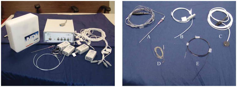
The Aurora system and electromagnetically tracked tools from Northern Digital and Traxtal Technologies. A: MagTrax needle; B: catheter; C: skin patch; D: sensor coil; E: guidewire. [Color version available online.]
Materials and methods
Several components are required to create an image-guided system that provides real-time navigation and image overlay for the physician. One key component is the registration module, which is responsible for registering the image coordinate system of the patient with the coordinate system of the tracking device so that the tracked tools can be visualized in relation to the preoperative images. For abdominal applications, motion compensation algorithms are also important to track organ movement to increase the accuracy of the system. In this section, we explain how we have designed our software application to address these issues and describe our respiratory motion phantom.
Registration
Registration is a major research topic in the medical imaging literature, and many different registration techniques have been used in image-guided systems. For our work, we have implemented and extended paired-point, orientation-based and needle-based registration methods as described below.
Paired-point registration
Paired-point registration is the most widely used method of registration for image-guided surgery. In a typical implementation, fiducials are placed on the body before a preoperative CT or MR scan. These are then sampled with a tracked pointer to determine the patient space coordinates. The image space coordinates (obtained from the preoperative scan) and patient space coordinates are matched, and a registration matrix is calculated. Since the flexibility of the skin can cause errors in registration [3], it is important to choose relatively stable portions of the body for marker placement.
Several extensions to the basic paired-point registration algorithm have been proposed to increase the registration accuracy. We proposed a method in which the fiducial positions are recorded over an entire respiratory cycle [4]. To minimize fiducial registration error (FRE) and increase the registration accuracy, we search for a point in the respiratory cycle where the fiducial locations best match the locations in the preoperative scan. The results obtained using this method are illustrated in Figure 2. The FRE and target registration error (TRE) [5] are evaluated over the entire respiratory period. In general the point in the cycle that gives the lowest FRE value gives the lowest TRE result. After performing a brute-force landmark registration match over the whole respiratory cycle, the time point which gives the lowest registration error is selected for the registration procedure. This technique has been incorporated into our image-guided system by using an electromagnetically tracked skin marker developed by Traxtal, Inc. as shown in Figure 1 (tool C). The skin marker is a 6-DOF device that attaches to the skin with adhesive tape.
Figure 2.
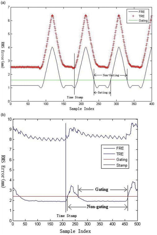
Diagram for respiratory cycle of phantom (a) and swine studies (b). Time Stamp identifies the minimum FRE/TRE value; Gating indicates the breath-hold period; and Non-gating indicates the entire respiratory cycle. [Color version available online.]
By using tracked skin markers during the intervention, it is also possible to register the fixed preoperative points with the moving tracked points to update the transformation in real time. This dynamic registration method has been successfully tested in several interventional experiments and found to improve the accuracy of the system.
Orientation-based registration
Liu, Cevikalp and Fitzpatrick introduced an extension to the standard paired-point approach to rigid-body registration that uses the orientation of the sensor coils as well as the positions of their centroids [6]. With this method, three-dimensional registration can be performed with only two sensor coils, as compared to the usual method based on three or more points. To incorporate the marker orientation information into the registration, the singular value decomposition (SVD) method is used to solve the following equations:
| (1) |
| (2) |
where (P, A) and (Q, B) are the marker position vectors and rotation matrices in the image and electromagnetic space, and R and T are the rotation matrix and translation vector of the transform. Formulas (1) and (2) are used to solve for the cross-covariance matrix. The transform shown in formula (3) is defined to reduce the computational complexity [7]:
| (3) |
Pos is the position of an offset point along the needle from the marker's position. The variable Pos thus combines the information from the orientation A, the translation P, and the offset. Expanding formula (3) with (1) and (2) gives the following:
| (4) |
Pos and Pos′ represent the original and transformed positions from the same point of the needle. The orientation registration is then performed through the normal paired-point registration method instead of solving formulas (1) and (2) for translation and orientation separately. For each cylinder-like needle tool, two points are selected, one at each end of the sensor coil which has been embedded in the tip of the needle. Thus, four points from two tracked needles are used in the registration. Our group tested this method in several vertebroplasty experiments using a spine phantom, as described in reference 8.
Needle-based registration
The two methods discussed so far rely on a point-based registration algorithm. To increase the registration accuracy, we have developed a shape-based registration method [9]. Three needles are implanted near the target area to define a volume through which the procedure needle will pass. As tracked needles as small as 22-gauge are now available, implanting three needles in the liver may be clinically feasible. Multiple points along these needles are then used in the registration. The procedure is as follows:
Implant three non-parallel, small-gauge tracked needles in the liver.
Obtain a pre-operative CT scan.
Segment the needles to obtain the image space points.
Sample the sensor coils embedded in the needles to obtain the corresponding points in electromagnetic space.
Process the sampled points to reduce the noise generated by the tracking system.
Use an Iterative Closest Point (ICP) algorithm and simulated annealing optimization method to compute the transform between image space and electromagnetic space.
The ICP algorithm is generally used to minimize the root mean square (RMS) distance between two feature point sets. However, it may find local minima, especially in noisy feature sets. To ensure that the point found by the ICP algorithm is a global minimum, a simulated annealing algorithm is employed [10,11]. An ICP algorithm with a Levenberg-Marquardt solver is used to attain each local minima position. At each of these points, a simulated annealing algorithm is applied to the transformation to perturb out and find the global minimum. The energy function representing the distance between two point sets is defined in formula (5):
| (5) |
A and B are the source and destination point sets; R and T are the rotation and translation matrices from point set A to B, respectively; and CP is the operator that finds the closest point in another data set. Our method applies the simulated annealing algorithm directly to the transformation parameters of each local minimum, as described in formula (6):
| (6) |
p̃i represents the disturbed parameters around the last Levenberg-Marquardt solution position that are used for optimization. LM is the general Levenberg-Marquardt solver. The registration process is plotted in Figure 3. Figure 3a shows the initial positions of the three needles in the image space and the tracked path for each of them. Figure 3b shows the positions and tracked path after the registration; they are nearly perfectly aligned.
Figure 3.

Positions of the needles and tracking path before (left) and after (right) registration. [Color version available online.]
Respiration motion compensation
Movement of internal organs during the respiratory cycle will decrease the accuracy of surgical navigation in the abdominal region. Since organs in the abdominal region can move by as much as 20 or 30 mm during respiration [12], static registration methods based on fiducials and preoperative CT scans are not optimal for abdominal navigation. Consequently, tracking or predicting the internal movement or deformation is a critical issue for any image-guided surgery system designed for abdominal procedures. One proposed method predicts internal organ position based on movement of external markers [13,14]. However, the accuracy of this approach is dependent on a consistent breathing pattern. A different approach is to use an implanted, electromagnetically tracked needle to directly measure the real-time organ movement.
Our prototype navigation system uses three implanted, tracked needles and a modified orientation-based registration algorithm, as described earlier, to dynamically compensate for respiration-induced motion in real time. An affine transform proposed by Horn [15], with translation, rotation, scale and shear operations, is used to simulate the small-range deformation. Other researchers have also proposed deformable models of organs with anisotropic scale and shear behavior [16–18].
A 3D affine transform has 12 parameters. In our case, we derive six 3-DOF points from the three 5-DOF needles and use them to solve the real-time affine transformation. Generally, the tip point and a second point that has a preset offset to the tip of each needle are chosen for the computation. A fourth needle, whose tip represents the target point, is used in the experiment for validation. Three internally tracked needles provide accurate registration and compensation, but this technique may not be acceptable to all clinicians. In abdominal interventions, some other non-invasive tracked tools, which are placed close to the target, can be used instead of the needles. In our tracked ultrasound application, three tracked skin patches are used to provide the motion compensation to align the ultrasound images with the resliced CT images.
Software design
We have created a prototype surgical navigation system called Navigator that integrates the registration methods discussed earlier with the Aurora electromagnetic tracking system. This system consists of a number of software components that are structure and user interface independent. The open-source software toolkits ITK and VTK are integrated into the system as the main pipeline. ITK is used to read DICOM images and perform semiautomated segmentation and registration. VTK is used to provide visualization for the system. Additional components such as manual segmentation, contour interpolation and ultrasound support were created and integrated into the package. MFC is used to provide the user interface and was required for ActiveX support (which was needed for the ultrasound interface).
The Navigator user interface is shown in Figure 4. In this example, the tumor was manually segmented and reconstructed in the navigation viewer (Figure 4a, lower right), which is aligned along the needle's direction to show the navigation path. The local anatomy around the needle tip is also shown in this view. The system displays the real-time registration error graphically so the best registration time and position can be easily visualized. In addition, several semi-automatic segmentation algorithms were implemented and manual segmentation was provided as an alternative. To improve the speed of manual segmentation, a fast and robust contour interpolation method was developed to minimize the difference between adjacent contour control points.
Figure 4.
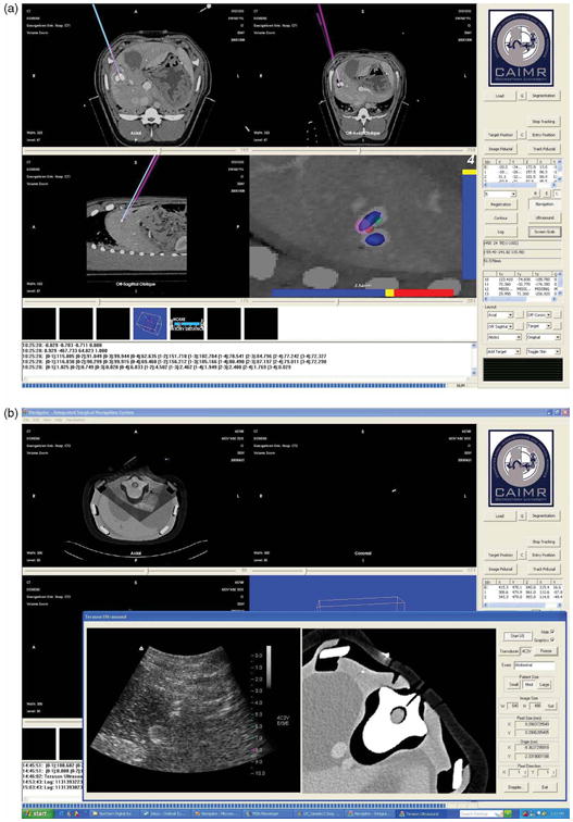
User interface of the Navigator system. (a) A display showing the axial, sagittal, coronal, and tool-tip views. (b) Integration of the tracked ultrasound. An ultrasound image and re-sliced CT image from the same plane are reconstructed and compared. [Color version available online.]
The system supports up to 8 simultaneously tracked tools and dynamic referencing as described earlier. The program provides various display modes for the physician. These include 2D viewers; including axial/coronal/sagittal viewers; oblique and slab-MIP viewers; 3D renderings a motion tracking viewer; and target and navigation viewers. In recent work, a 2D ultrasound probe from Terason, Inc. (Burlington, MA, USA) has been integrated as shown in the lower left view of Figure 4b [19]. For record keeping, all tracked tool positions are monitored in real time and all the operations are logged. Finally, a screen-save function has been implemented.
Phantom design and validation
To test our system in the laboratory environment we developed a human torso model with a custom-molded liver phantom (Figure 5). Two elliptical simulated tumors (maximum diameters of 3.1 and 2.2 cm) containing radio-opaque CT contrast were incorporated into the liver model prior to curing to serve as tumor targets. The liver was attached to a linear motion platform at the base of the torso's right abdomen. The platform allows the phantom to simulate physiologic cranial-caudal motion of the liver with options for respiratory rate control, breath depth, and breath hold. A ribcage and single-layer latex skin material (Limbs and Things, Bristol, UK) were added to provide a skin surface.
Figure 5.
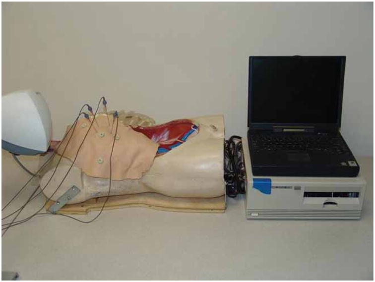
Respiratory phantom showing dummy torso with rib cage and skin, along with the control interface and a laptop computer. [Color version available online.]
Results
Using preoperative CT scans and the image-guided overlay, 16 liver tumor punctures were attempted in the phantom model. We successfully hit the tumor in 14 of 16 attempts (87.5%). Each attempt took from 106 to 220 seconds [20].
Based on these results, approval was obtained from the Georgetown Animal Care and Use Committee to use the system to target the liver in swine experiments, as shown in Figure 6. Purified agar was dissolved in distilled water and diluted in CT contrast medium (1 :10 v/v dilution), and 1–2 ml was percutaneously injected into the swine liver using an 18-g needle. Two agar injections were performed for each animal to serve as nodular targets approximately 1–2 cm in diameter.
Figure 6.
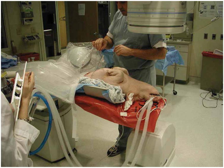
Swine animal study in the fluoroscopy suite under an approved protocol. [Color version available online.]
The experimental procedure was as follows:
Place skin fiducials, tracked skin patches, or needles on the animal as image markers for registration depending on the algorithm used.
Obtain a CT scan of the abdominal region using 1 mm axial images.
Move the animal to the angiography suite and transfer the images to our image-guided system using the DICOM format.
Segment the tumor or target using semiautomatic or manual techniques.
Depending on the registration method used, identify the fiducial points in the image data set or segment the path of the implanted needle.
Touch the fiducial points with an electromagnetically tracked tool, or locate the tracked points along the needle.
Perform the registration and return the root mean square (RMS) error as an indicator of the registration accuracy.
Determine the entry and target points to plan the path.
Perform the procedure (needle insertion) guided by the real-time image visualization using a tracked needle.
Analyze and report the final needle position from the image overlay and confirm the actual result by taking two orthogonal fluoroscopic images.
Two experienced interventional radiologists and two radiology residents participated in the study [21]. Thirty-two targeting passes into a nodule were made in two swine (16 passes into each animal). Registration and actual needle punctures were performed while the swine was in the full expiratory phase of the respiratory cycle. Each physician advanced the needle towards the nodule in the swine using only the image overlay; no real-time scans were performed. Once the physician was satisfied that the needle tip was in the desired final location, the needle pass was considered complete and respective times were recorded. Needle position was then verified with fluoroscopic imaging in AP and lateral (orthogonal) views, and images were captured for off-line analysis. Root mean square distances, from the final needle tip position to the center of the nodule, were calculated. The average registration error between the CT coordinate system and the electromagnetic coordinate system was 1.9 ± 0.4 mm. The distance from the final needle tip position to the center of the tumor was 8.3 ± 3.7 mm in the swine. The attending radiologists hit the tumor in 10 of their 16 attempts and the residents also hit the tumor in 10 of their 16 attempts.
This study showed the feasibility of using electromagnetic tracking in the fluoroscopy environment to provide guidance during minimally invasive procedures. This study was completed with a prototype version of the Aurora field generator (the egg-shaped device visible under the clear plastic cover in Figure 6). Northern Digital, Inc. has since released a new commercial version of the field generator as shown in Figure 7 (the black rectangular box on the right). Figure 7 also shows our most recent animal study in the CT environment, where there is more metal present that might distort the magnetic field. In particular, the CT table has some metal components underneath that move the table, while the fluoroscopy table is completely metal-free in the area below the field generator. We do not yet have definitive results in the CT environment, but our preliminary results indicate that the new system can also be used in this environment.
Figure 7.
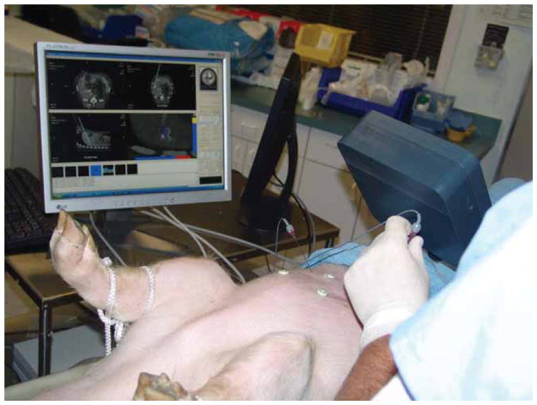
Swine animal study in the CT suite completed under an approved protocol showing the Navigator user interface. [Color version available online.]
Discussion
This paper has presented our work in developing an image-guided system based on electromagnetic tracking for abdominal interventions. While image guidance based on bony landmarks, such as in the spine and brain, is now well established, image guidance for abdominal interventions is still in the research stage. Our studies in the interventional suite, as presented here, have convinced us that electromagnetic tracking can be used to track internal organs for these procedures. Since these organs are deformable and move with respiration, rigid-body registration techniques such as paired-point matching may not be suitable for image guidance. However, these techniques may be extended with other registration methods that are presented in this paper, which may provide sufficient accuracy in the area of interest to assist the physician in completing these procedures. Additional studies are needed to determine the level of fidelity required and the appropriate techniques to create a clinically viable system.
Recent developments in electromagnetic tracking have provided two key advances: 1) smaller sensors which can now be embedded at the tips of medical instruments; and 2) better tracking in the neighborhood of metallic materials. These advances have made it possible to develop image guidance for abdominal interventions and we are in the process of applying for institutional review board (IRB) approval for a clinical trial. In our experience in both the fluoroscopy and CT suites, the effects of metallic materials in the environment can be managed and the electromagnetic tracking system was sufficiently accurate to provide image guidance.
The best display for image guidance is still a topic of ongoing research. The typical four-view display provided by most image-guided systems is a good starting point and specialized views such as a tooltip view have also been found to be useful. This display is only part of an overall workstation for image guidance, which should also include tools for path planning and segmentation of target structures as well as structures to be avoided. The development of such a workstation must be a partnership between clinical and technical personnel. We have found that an iterative process, where the latest version of the software is used in each successive animal study and improvements desired by the physician are noted and incorporated in the next release, works well to create a display that meets the clinical requirements.
It is our belief that we are only at the beginning of the development of a new generation of image-guided systems that will be capable of handling organ motion and deformation. While tracking technology will continue to evolve, we believe that the current generation of electromagnetic tracking is sufficiently accurate to permit prototype systems to be developed and clinical trials to begin. To assist researchers in developing prototype systems, we have been developing an open-source framework called the image-guided surgical toolkit (IGSTK) along with researchers from Kitware, Arizona State University, and Atamai [22]. Researchers are free to download the toolkit; more information can be found at www.igstk.org.
Acknowledgments
This work was funded by U.S. Army grants DAMD17-99-1-9022 and W81XWH-04-1-0078. The content of this manuscript does not necessarily reflect the position or policy of the U.S. Government.
Footnotes
Part of this research was previously presented at the 19th International Congress and Exhibition on Computer Assisted Radiology and Surgery (CARS 2005), held in Berlin, Germany, in June 2005.
References
- 1.Li Q, Zamorano L, Jiang Z, Gong JX, Pandya A, Perez R, Diaz F. Effect of optical digitizer selection on the application accuracy of a surgical localization system - a quantitative comparison between the OPTOTRAK and FlashPoint tracking systems. Comput Aided Surg. 1999;4(6):314–321. doi: 10.1002/(SICI)1097-0150(1999)4:6<314::AID-IGS3>3.0.CO;2-G. [DOI] [PubMed] [Google Scholar]
- 2.Birkfellner W, Watzinger F, Wanschitz F, Ewers R, Bergmann H. Calibration of tracking systems in a surgical environment. IEEE Trans Med Imaging. 1998;17(5):737–742. doi: 10.1109/42.736028. [DOI] [PubMed] [Google Scholar]
- 3.Rohlfing T, Maurer CR, Jr, Dell W, Zhong J. Modeling liver motion and deformation during the respiratory cycle using intensity-based free-form registration of gated MR images. Med Phys. 2004;31:427–432. doi: 10.1118/1.1644513. [DOI] [PubMed] [Google Scholar]
- 4.Zhang H, Banovac F, Cleary K. Increasing registration precision for liver movement during respiratory cycle using magnetic tracking. In: Lemke HU, Inamura K, Doi K, Vannier MK, Farman AG, editors. Computer Assisted Radiology and Surgery; Proceedings of the 19th International Congress and Exhibition (CARS 2005); Berlin, Germany. June 2005; Amsterdam: Elsevier; 2005. pp. 571–576. [Google Scholar]
- 5.Fitzpatrick JM, West JB, Maurer CR., Jr Predicting error in rigid-body point-based registration. IEEE Trans Med Imaging. 1998;17(5):694–702. doi: 10.1109/42.736021. [DOI] [PubMed] [Google Scholar]
- 6.Liu X, Cevikalp H, Fitzpatrick JM. Marker orientation in fiducial registration. Proceedings of SPIE Medical Imaging. 2003;5032:1176–1185. SPIE. [Google Scholar]
- 7.Cleary K, Zhang H, Glossop N, Levy E, Bonavac F. Electromagnetic tracking for image-guided abdominal procedures: overall system and technical issues. Proceedings of 27th Annual International Conference of IEEE EMBC; Shanghai, China. September 2005; p. 268. [DOI] [PubMed] [Google Scholar]
- 8.Watson V, Glossop N, Kim A, Lindisch D, Zhang H, Cleary K. Image-guided percutaneous vertebroplasty using electromagnetic tracking. In: Langlotz F, Davies BL, Schlenzka D, editors. Proceedings of the 5th Annual Meeting of the International Society for Computer Assisted Orthopaedic Surgery (CAOS-International); Helsinki, Finland. June 2005; pp. 492–495. [Google Scholar]
- 9.Zhang H, Banovac F, Glossop N, Cleary K. Two-stage registration for real-time deformable simulation using magnetic tracking device. In: Duncan J, Gerig G, editors. Part 2 Lecture Notes in Computer Science; Proceeding of the 8th International Conference on Medical Image Computing and Computer Assisted Intervention (MICCAI 2005); Palm Springs, CA, USA. October 2005; Berlin: Springer; 2005. pp. 992–999. [DOI] [PubMed] [Google Scholar]
- 10.Zhang Z. Iterative point matching for registration of free form curves and surfaces. Int J Computer Vision. 1994;13(2):119–152. [Google Scholar]
- 11.Penny GP, Edwards PJ, King AP, Blackall JM, Batchelor PG, Hawkes DJ. A stochastic iterative closest point algorithm (stochastICP). In: Niessen WJ, Viergever MA, editors. Lecture Notes in Computer Science; Proceedings of the 4th International Conference on Medical Image Computing and Computer-Assisted Intervention (MICCAI 2001); Utrecht, The Netherlands. October 2001; Berlin: Springer; 2001. pp. 762–769. [Google Scholar]
- 12.Clifford MA, Banovac F, Levy E, Cleary K. Assessment of hepatic motion secondary to respiration for computer assisted interventions. Comput Aided Surg. 2002;7:291–299. doi: 10.1002/igs.10049. [DOI] [PubMed] [Google Scholar]
- 13.Wong KH, Tang J, Zhang H, Varghese E, Cleary K. Prediction of 3D internal organ position from skin surface motion: results from electromagnetic tracking studies. In: Jeong TH, Bjelkhagen HI, editors. Proceedings of Medical Imaging. Vol. 5744. 2005. pp. 879–887. SPIE. [Google Scholar]
- 14.Schweikard A, Glosser G, Bodduluri M, Murphy M, Adler JR. Robotic motion compensation for respiratory movement during radiosurgery. Comput Aided Surg. 2000;5(4):263–277. doi: 10.1002/1097-0150(2000)5:4<263::AID-IGS5>3.0.CO;2-2. [DOI] [PubMed] [Google Scholar]
- 15.Horn BKP. Closed-form solution of absolute orientation using unit quaternions. J Optical Society of America A. 1987;4:629–642. [Google Scholar]
- 16.Klein GJ, Reutter BW, Huesman RH. 4D affine registration models for respiratory-gated PET. IEEE Nuclear Science Symposium. 2000;15:41–45. [Google Scholar]
- 17.Feldmar J, Ayache N. Rigid, affine and locally affine registration of free-form surfaces. Int J Computer Vision. 1996;18:99–119. [Google Scholar]
- 18.Pitiot A, Malandain G, Bardinet E, Thompson PM. Piecewise affine registration of biological images. Proceedings of Second International Workshop on Biomedical Image Registration (WBIR 2003); Philadelphia, PA. June 2003; pp. 91–101. [Google Scholar]
- 19.Zhang H, Banovac F, White A, Cleary K. Freehand 3D ultrasound calibration using an electromagnetically tracked needle. Proceedings of SPIE Medical Imaging 2006: Visualization, Image-guided Procedures and Display; In press. [Google Scholar]
- 20.Banovac F, Glossop ND, Lindisch D, Tanaka D, Levy E, Cleary K. Liver tumor biopsy in a respiring phantom with the assistance of a novel electromagnetic navigation device. In: Dohi T, Kikinis R, editors. Proceeding of the 5th International Conference on Medical Image Computing and Computer-Assisted Intervention (MICCAI 2002); Tokyo, Japan. September 2002; Berlin: Springer; 2002. pp. 200–207. [Google Scholar]
- 21.Banovac F, Tang J, Xu S, Lindisch D, Chung HY, Levy EB, Chang T, McCullough MF, Yaniv Z, Wood BJ, Cleary K. Precision targeting of liver lesions using a novel electromagnetic navigation device in physiologic phantom and swine. Med Phys. 2005;32(8):2698–2705. doi: 10.1118/1.1992267. [DOI] [PubMed] [Google Scholar]
- 22.Cheng P, Zhang H, Kim H, Gary K, Blake MB, Gobbi D, Aylward S, Jomier J, Enquobahrie A, Avila R, Ibanez L, Cleary K. IGSTK: framework and example application using an open source toolkit for image-guided surgery applications. Proceedings of SPIE Medical Imaging 2006: Visualization, Image-guided Procedures and Display; In press. [Google Scholar]


