Abstract
Proton and heteronuclear MRI/MRS using dual-tuned (DT) coils could provide both anatomical and metabolic images without repositioning the subject. However, it is technologically challenging to attain sufficiently electromagnetic (EM) decoupling between the heteronuclear channel and proton channel, and keep the imaging areas and profiles of two nuclear channels highly matched. In this study, a hybrid monopole/loop technique was proposed for DT coil design and this technique was validated by implementing and testing a DT 1H/23Na coil for MR imaging at 7T. The RF fields of the monopole (1H channel) and regular L/C loop (23Na channel) were orthogonal and intrinsically EM decoupled. Bench measurement results demonstrated the isolation between the two nuclear channels was better than -28 dB at both nuclear frequencies. Compared with the conventional DT coil using trap circuits, the monopole/loop DT coil had higher MR sensitivity for sodium imaging. The experimental results indicated that the monopole/loop technique might be a simple and efficient design for multinuclear imaging at ultrahigh fields. Additionally, the proposed DT coils based on the monopole/loop technique can be used as building blocks in designing multichannel DT coil arrays.
Keywords: Magnetic resonance image (MRI), dual-tuned (DT), radiofrequency coil, sodium, monopole, loop, decouple, trap, sensitivity, signal-to-noise ratio (SNR)
Introduction
MR imaging and spectroscopy of heteronuclear or non-proton (X-) nuclear, e.g., sodium (23Na) (1-4), phosphorus (31P) (5-8) and carbon (13C) (9-11), can provide physiological and metabolic information beyond the anatomic structure, which might be valuable for evaluation and characterization of human diseases. However, it is technically challenging to obtain heteronuclear MR spectroscopy or imaging because of the low natural abundance and concentration in living systems, rapid signal decay and low gyromagnetic ratio. Ultrahigh field MRI largely benefits the heteronuclear MR imaging due to its intrinsically high sensitivity. The dual-tuned (DT) coil (12-21), including the proton channel as well as heteronuclear channel, has the capability of performing static magnetic field (B0) shimming and providing both anatomic (by 1H) and physiological or metabolic (by X-nuclear) images without repositioning the subject. With these advantages, DT coils are preferred in heteronuclear MR spectroscopy and MR imaging.
One of the main challenges in the design of a DT coil is to suppress the crosstalk between the heteronuclear channel and the proton channel. The commonly used approach is to insert a parallel inductor and capacitor into the heteronuclear channel, which form a trap circuit and block the induced current at the proton frequency (22-24). However, the extra electronic components bring in additional losses, ultimately reducing the MR sensitivity and thus the imaging resolution for the heteronuclear images. An alternative method of designing DT coils is to use different coil types or resonant modes for proton and heteronuclear channels. In previous work, the microstrip/birdcage, microstrip/loop and common-mode (CM)/different-mode (DM) techniques have been employed in designing DT coils at ultrahigh fields (25-27).
In this study, we aim to use a monopole/loop technique for the DT coil design at ultrahigh fields. This design concept was realized by designing and constructing a 1H/23Na DT coil for MR imaging at 7T. The design technique was validated by standard RF testing and MR imaging experiments. Regular L/C loop was chosen for sodium imaging given that loop is more suitable for MR imaging at low frequencies and could provide higher sensitivity at the peripheral areas. Monopole coil (28,29) was selected for proton imaging due to its simple structure and advantages for ultrahigh field RF coil designs. The monopole was carefully placed across the center of the loop, making the RF fields of two nuclear channels orthogonal to each other and thus intrinsically electromagnetic (EM) decoupled. The resonant frequencies of the loop and monopole can be tuned independently to desired values. The proposed design does not need extra lossy components and should improve the MR sensitivity compared with the conventional trapped DT coil. To evaluate the benefits of the proposed monopole/loop DT coil, its performance was investigated and compared with a mononuclear sodium (MS) coil and a conventional trapped DT coil.
Materials and methods
Design and construction of the monopole/loop DT coil
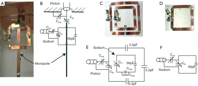
A monopole/loop DT coil, a trapped DT coil (22), and a MS coil were constructed to investigate their coil performance at 7T, as shown in Figure 1. For the three coils, the sodium loops have identical dimensions (8 cm × 8 cm) for a fair comparison. Two trimmer capacitors (Cms and Cts) in the sodium loops were used to match the impendence to 50 Ω and tuned the resonant frequency to 78.6 MHz, which is the sodium Larmor frequency of our 7T system. For the trapped DT coil, a parallel capacitor and inductor (referred to as the trap capacitor Ctrap and trap inductor Ltrap, respectively) were inserted into the sodium loop to block the current at proton frequency. The value of Ctrap was 4.7 pF and Ltrap was wound in five turns with a diameter of 5 mm. The gap between the turns of Ltrap was finely changed to tune the trap circuit to the proton frequency.
Figure 1.
Photographs and equivalent circuits of a monopole/loop 1H/23Na dual-tuned (DT) coil (A and B), a trapped 1H/23Na DT coil (C and E) and a mononuclear 23Na coil (D and F). The dimensions of all sodium loops are exactly the same (8 cm × 8 cm) for a fair comparison.
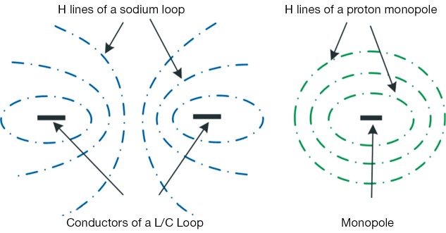
For the monopole/loop DT coil, the proton channel is consisting of a monopole (length 25 cm, Figure 1A,B) which is perpendicular to the ground (dimension 40 cm × 40 cm). The monopole coil crossed the center of the loop coil, making RF fields of the two nuclear channels are orthogonal, as shown in Figure 2. For the trapped DT coil, the proton loop measured in the size of 11 cm × 11 cm and had three fixed capacitors (3.3 pF) and a trimmer capacitor equally distributed along the conductors, as shown in Figure 1C,E. The proton channels were matched to 50 Ω and tuned to 297.2 MHz, which is the proton Larmor frequency of our 7T system. All conductors were made from 10-mm-wide copper tape (3M, St. Paul, MN, USA). All fix capacitors are from ATC Company (Huntington Station, NY, USA) and all trimmer capacitors are from Voltronics Company (Denville, NJ, USA) with a range of 1-30 pF.
Figure 2.

Illustration of the magnetic field distributions of a sodium L/C loop (left) and a proton monopole (right). The illustration clearly demonstrated that the magnetic fields of the two nuclear channels are orthogonal when the monopole was put across the center of the loop.
Bench tests and MR imaging experiments
Scattering (S-) parameters including reflection coefficients S11 and transmission coefficient S21 of the two DT coils and the MS coil were measured with an Agilent 5071C network analyzer. The S-parameter results were recorded when the coils were loaded with a cylindrical water phantom (diameter 16 cm, volume 5 L) containing 100 mM NaCl. To assess the additional loss of the monopole/loop and trapped DT coils, the unloaded and loaded quality (Q) values of the two coils were measured and compared with those of a MS coil.
The proton and sodium images on the water phantom of the three coils were obtained using gradient echo (GRE) sequences. Before the scan of sodium MR experiments, B0 shimming was carried on by using the proton channels. For the MS coil, another single-tuned proton loop coil was employed for B0 shimming. The slice chosen for MR imaging was in the transverse plane and crossed the center of the sodium loop. The sodium imaging acquisition parameters were as follow: TR =100 ms, TE =4.5 ms, field of view (FOV) =200×200 mm2, matrix =64×64, slice thickness =5.5 mm, bandwidth =260 Hz/pixel, in-plane resolution =3.15×3.15 mm2, number of averages =10. The proton imaging parameters were: flip angle (FA) =25 deg, TR =100 ms, TE =10 ms, FOV =200×200 mm2, matrix =256×256, slice thickness =2 mm, bandwidth =320 Hz/pixel, number of averages =1. During the MR experiments, the cylindrical water phantom was placed 2 cm below the coils. All imaging data were acquired on a 7T whole-body MRI scanner (MAGNETOM, Siemens Healthcare, Erlangen, Germany).
Results
Measured S parameters and Q values
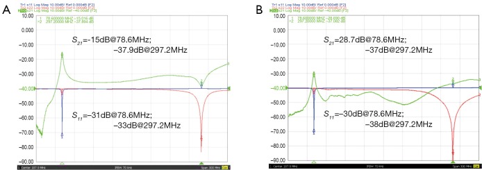
Figure 3A shows the S11 and S21 plots of the sodium and proton channels of the trapped DT coil. With the trap circuit, the isolation of the two nuclear channels could achieve –37.9 dB at proton frequency, indicating good trap performance. The previous work has shown that the high frequency coil has a relatively small impact on the low frequency coil (22). This phenomenon has also been validated in this study that the coupling at sodium frequency was still acceptable (–15 dB) even that no trap circuit at this frequency was used. Figure 3B show the S-parameter plots of the two nuclear channels of the monopole/loop DT coil. The isolation of two nuclear channels at sodium and proton frequencies was –28.7 and –37 dB, respectively. It is clear from Figure 2B that the interaction of two channels was sufficiently small in a very broad frequency range from 50 to 350 MHz. These results indicate that the two channels of the monopole/loop DT coil were intrinsically decoupled and no extra decoupling methods are needed. S11 results from Figure 2A,B demonstrated that both proton and sodium channels were well matched to 50 Ω at desired frequencies.
Figure 3.

S11 and S21 plots of the two nuclear channels of the trapped DT coil (A) monopole/loop DT coil (B). DT, dual-tuned.
The unloaded and loaded Q values of the two nuclear channels of the three coils are given in Table 1. The ratio of unloaded Q and loaded Q for a MS coil is 5.74, but it decreases to only 3.21 when the trap circuit is inserted. It is worth noting that the Q ratio decrease is mainly due to low unloaded Q, which is probably because of the resistance of the trap circuit. For the monopole/loop DT coil, however, the ratio still achieve 5.67 and the decrease of Q ratio is less than 5%. For the monopole/loop DT coil, both unloaded and loaded Q values of the sodium loop are almost the same as the MS coil, indicating good MR sensitivity performance. Compared with the proton loop of the trapped DT coil, the monopole has a relatively lower Q values in both unloaded and loaded cases, which is consistent with the previous work (28,29).
Table 1. Unladed and loaded Q values of the MS coil, trapped DT coil and monopole/loop DT coil.
|
23Na (78.6 MHz) |
1H (297.2 MHz) |
|||||
|---|---|---|---|---|---|---|
| MS coil | Trapped DT | M/L DT | Trapped DT | M/L DT | ||
| Qun | 425 | 225 | 414 | 110 | 9.1 | |
| Qload | 74 | 70 | 73 | 30 | 2.8 | |
| Qun/Qload | 5.74 | 3.21 | 5.67 | 3.67 | 3.25 | |
MS, mononuclear sodium; DT, dual-tuned; Q, quality.
MR Imaging results
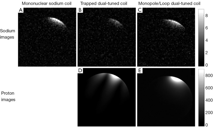
Figure 4A-C show the sodium images on water phantom of the three coils. Figure 4A is the axial images acquired with the MS coil. When the trap circuit was inserted in the sodium loop, strong sensitivity decrease (~50%) is observed, as shown in Figure 4B. The monopole/loop DT coil, however, has similar sensitivity with the MS coil (Figure 4C). The MR images are also in agreement with the Q value results as described above. Figure 4D,E show the proton images of the trapped and monopole/loop DT coils. It is well know that the transmit field (B1+) and receive field (B1–) of a loop coil have an asymmetrical pattern at the high frequency of 300 MHz (30,31). This asymmetrical pattern resulted in dark lines in the MR sensitivity images, as shown in Figure 4D. The monopole coil, however, has a relatively symmetrical B1 field distribution (28) and thus no dark lines were observed in the images (Figure 4E).
Figure 4.
Sodium and proton images of the mononuclear sodium coil (A), trapped dual-tuned (DT) 1H/23Na coil (B and D) and monopole/loop dual-tuned 1H/23Na coil (C and E). Compared with trapped DT coil, the monopole/loop DT coil has higher MR sensitivity for sodium imaging. The cylindrical phantom (diameter 16 cm, volume 5 L) containing 100 mM NaCl was placed 2 cm below the coils.
Discussion and conclusions
In this study, a monopole/loop technique was proposed for multinuclear coil designs, and this technique was validated by implementing a DT 1H/23Na coil for MR imaging at 7T. The monopole and L/C loop coils were chosen for 1H and 23Na MR imaging, respectively. The monopole (1H) was centrally crossed the loop (23Na channel) to ensure that the RF fields of the two nuclear channels are orthogonal (as indicated in Figure 2) and gain intrinsic decoupling between the two nuclear channels. The bench measurement results demonstrated that the interaction between 1H channel and 23Na channels was sufficiently small (<–28 dB) in a very broad frequency range from 50 to 350 MHz even that no extra decoupling methods were employed (Figure 3B).
The commonly used L/C trap circuit could also suppress the cross-talk of the two nuclear channels at 1H frequency. However, the additional loss of trap resulted in pronounced decrease of Q ratio and MR sensitivity for 23Na imaging (Figure 4A,B). In the proposed monopole/loop design, however, nearly no decrease in the 23Na sensitivity was observed (Figure 4A,C). This is likely because no extra lossy components were added in the sodium loop and the interaction of the monopole and loop is neglectable. It is also worth noting that, compared with the conventional loop coil, the sensitivity profile of the monopole coil is more advantageous for B0 shimming (Figure 4D,E) since the imaging areas and profiles of the two nuclear channels of the monopole/loop design are highly matched. This monopole/loop technique for DT coil could also be extended to multi-channel array design when the inner-coupling of proton and sodium arrays is reduced by using existing decoupling methods (21,32-38).
Acknowledgments
Funding: This work was supported in part by the Chinese National Major Scientific Equipment R&D Project (Grant No. ZDYZ2010-2), the Ministry of Science and Technology of China Grant (2012CB825500), the National Natural Science Foundation of China Grant (51228702), the Chinese Academy of Sciences Grants (XDB02010001, XDB02050001), and National Institutes of Health (NIH) R01EB008699.
Author contribution: Conceived and designed the study: Xiaoliang Zhang, Xinqiang Yan. Performed the experiments and collected data: Xinqiang Yan. Analyzed the data: Xiaoliang Zhang, Xinqiang Yan. Contributed materials/analysis tools: Rong Xue. Wrote the paper: Xinqiang Yan, Xiaoliang Zhang, Rong Xue.
Disclosure: The authors declare no conflict of interest.
References
- 1.Nishimura T, Sada M, Sasaki H, Yamada N, Yamada Y, Yutani C, Amemiya H, Fujita T, Akutsu T, Manabe H.Sodium nuclear magnetic resonance imaging of acute cardiac rejection in heterotopic heart transplantation. Cardiovasc Res 1989;23:561-6 [DOI] [PubMed] [Google Scholar]
- 2.Boehmer JP, Metz KR, Mao JT, Briggs RW. Spatial mapping of 23Na NMR signals by two-dimensional rotating frame imaging. Magn Reson Med 1990;16:335-41 [DOI] [PubMed] [Google Scholar]
- 3.Thulborn KR, Davis D, Adams H, Gindin T, Zhou J. Quantitative tissue sodium concentration mapping of the growth of focal cerebral tumors with sodium magnetic resonance imaging. Magn Reson Med 1999;41:351-9 [DOI] [PubMed] [Google Scholar]
- 4.Ouwerkerk R, Bleich KB, Gillen JS, Pomper MG, Bottomley PA. Tissue sodium concentration in human brain tumors as measured with 23Na MR imaging. Radiology 2003;227:529-37 [DOI] [PubMed] [Google Scholar]
- 5.Ugurbil K, Rottenberg H, Glynn P, Shulman RG. 31P nuclear magnetic resonance studies of bioenergetics and glycolysis in anaerobic Escherichia coli cells. Proc Natl Acad Sci U S A 1978;75:2244-8 [DOI] [PMC free article] [PubMed] [Google Scholar]
- 6.Ackerman JJ, Grove TH, Wong GG, Gadian DG, Radda GK. Mapping of metabolites in whole animals by 31P NMR using surface coils. Nature 1980;283:167-70 [DOI] [PubMed] [Google Scholar]
- 7.Bottomley PA, Cousins JP, Pendrey DL, Wagle WA, Hardy CJ, Eames FA, Mccaffrey RJ, Thompson DA. Alzheimer dementia: quantification of energy metabolism and mobile phosphoesters with P-31 NMR spectroscopy. Radiology 1992;183:695-9 [DOI] [PubMed] [Google Scholar]
- 8.Lei H, Zhu XH, Zhang XL, Ugurbil K, Chen W. In vivo 31P magnetic resonance spectroscopy of human brain at 7 T: an initial experience. Magn Reson Med 2003;49:199-205 [DOI] [PubMed] [Google Scholar]
- 9.Reo NV, Ewy CS, Siegfried BA.Ackerman JJH. High-field 13C NMR spectroscopy of tissue in Vivo. A double-resonance surface-coil probe. J Magn Reson 1984;58:76-84 [Google Scholar]
- 10.Chen W, Adriany G, Zhu XH, Gruetter R, Ugurbil K. Detecting natural abundance carbon signal of NAA metabolite within 12-cm(3) localized volume of human brain using H-1-{C-13} NMR spectroscopy. Magn Reson Med 1998;40:180-4 [DOI] [PubMed] [Google Scholar]
- 11.Choi IY, Tkác I, Ugurbil K, Gruetter R. Noninvasive measurements of [1-(13)C]glycogen concentrations and metabolism in rat brain in vivo. J Neurochem 1999;73:1300-8 [DOI] [PubMed] [Google Scholar]
- 12.Adriany G, Gruetter R.A half-volume coil for efficient proton decoupling in humans at 4 tesla. J Magn Reson 1997;125:178-84 [DOI] [PubMed] [Google Scholar]
- 13.Shen GX, Boada FE, Thulborn KR. Dual-frequency, dual-quadrature, birdcage RF coil design with identical B1 pattern for sodium and proton imaging of the human brain at 1.5 T. Magn Reson Med 1997;38:717-25 [DOI] [PubMed] [Google Scholar]
- 14.Shen GX, Wu JF, Boada FE, Thulborn KR. Experimentally verified, theoretical design of dual-tuned, low-pass birdcage radiofrequency resonators for magnetic resonance imaging and magnetic resonance spectroscopy of human brain at 3.0 Tesla. Magn Reson Med 1999;41:268-75 [DOI] [PubMed] [Google Scholar]
- 15.Wang C, Li Y, Wu B, Xu D, Nelson SJ, Vigneron DB, Zhang X. A practical multinuclear transceiver volume coil for in vivo MRI/MRS at 7 T. Magn Reson Imaging 2012;30:78-84 [DOI] [PMC free article] [PubMed] [Google Scholar]
- 16.Ha S, Hamamura MJ, Nalcioglu O, Muftuler LT. A PIN diode controlled dual-tuned MRI RF coil and phased array for multi nuclear imaging. Phys Med Biol 2010;55:2589-600 [DOI] [PubMed] [Google Scholar]
- 17.Kim JH, Moon CH, Park BW, Furlan A, Zhao T, Bae KT. Multichannel transceiver dual-tuned RF coil for proton/sodium MR imaging of knee cartilage at 3 T. Magn Reson Imaging 2012;30:562-71 [DOI] [PubMed] [Google Scholar]
- 18.Pang Y, Xie Z, Xu D, Kelley DA, Nelson SJ, Vigneron DB, Zhang X. A dual-tuned quadrature volume coil with mixed λ/2 and λ/4 microstrip resonators for multinuclear MRSI at 7 T. Magn Reson Imaging 2012;30:290-8 [DOI] [PMC free article] [PubMed] [Google Scholar]
- 19.Brown R, Madelin G, Lattanzi R, Chang G, Regatte RR, Sodickson DK, Wiggins GC. Design of a nested eight-channel sodium and four-channel proton coil for 7T knee imaging. Magn Reson Med 2013;70:259-68 [DOI] [PMC free article] [PubMed] [Google Scholar]
- 20.Kaggie JD, Hadley JR, Badal J, Campbell JR, Park DJ, Parker DL, Morrell G, Newbould RD, Wood AF, Bangerter NK. A 3 T sodium and proton composite array breast coil. Magn Reson Med 2014;71:2231-42 [DOI] [PMC free article] [PubMed] [Google Scholar]
- 21.Avdievich NI. Transceiver-Phased Arrays for Human Brain Studies at 7 T. Appl Magn Reson 2011;41:483-506 [DOI] [PMC free article] [PubMed] [Google Scholar]
- 22.Alecci M, Romanzetti S, Kaffanke J, Celik A, Wegener HP, Shah NJ. Practical design of a 4 Tesla double-tuned RF surface coil for interleaved 1H and 23Na MRI of rat brain. J Magn Reson 2006;181:203-11 [DOI] [PubMed] [Google Scholar]
- 23.Dabirzadeh A, McDougall MP. Trap design for insertable second-nuclei radiofrequency coils for magnetic resonance imaging and spectroscopy. Magnetic Resonance 2009;35B:121-32 [Google Scholar]
- 24.Meyerspeer M, Roig ES, Gruetter R, Magill AW. An improved trap design for decoupling multinuclear RF coils. Magn Reson Med 2014;72:584-90 [DOI] [PubMed] [Google Scholar]
- 25.Wiggins GC, Brown R, Fleysher L, Zhang B, Stoeckel B, Inglese M, Sodickson DK. A Nested Dual Frequency Birdcage/Stripline Coil for Sodium/Proton Brain Imaging at 7T. Proc Intl Soc Mag Reson Med 2010;18:2159 [Google Scholar]
- 26.Yan X, Shi L, Wei L, Zhuo Y, Zhou XJ, Xue R. A hybrid sodium/proton double-resonant transceiver array for 9.4T MRI. Microwave Workshop Series on RF and Wireless Technologies for Biomedical and Healthcare Applications (IMWS-BIO) 2013:1-3. [Google Scholar]
- 27.Pang Y, Zhang X, Xie Z, Wang C, Vigneron DB. Common-mode differential-mode (CMDM) method for double-nuclear MR signal excitation and reception at ultrahigh fields. IEEE Trans Med Imaging 2011;30:1965-73 [DOI] [PMC free article] [PubMed] [Google Scholar]
- 28.Hong SM, Park JH, Woo MK, Kim YB, Cho ZH. New design concept of monopole antenna array for UHF 7T MRI. Magn Reson Med 2014;71:1944-52 [DOI] [PubMed] [Google Scholar]
- 29.Yan X, Zhang X, Wei L, Xue R.Magnetic wall decoupling method for monopole coil array in ultrahigh field MRI: a feasibility test. Quant Imaging Med Surg 2014;4:79-86 [DOI] [PMC free article] [PubMed] [Google Scholar]
- 30.Yang QX, Wang J, Zhang X, Collins CM, Smith MB, Liu H, Zhu XH, Vaughan JT, Ugurbil K, Chen W. Analysis of wave behavior in lossy dielectric samples at high field. Magn Reson Med 2002;47:982-9 [DOI] [PubMed] [Google Scholar]
- 31.Collins CM, Yang QX, Wang JH, Zhang X, Liu H, Michaeli S, Zhu XH, Adriany G, Vaughan JT, Anderson P, Merkle H, Ugurbil K, Smith MB, Chen W. Different excitation and reception distributions with a single-loop transmit-receive surface coil near a head-sized spherical phantom at 300 MHz. Magn Reson Med 2002;47:1026-8 [DOI] [PubMed] [Google Scholar]
- 32.Zhang X, Webb A.Design of a capacitively decoupled transmit/receive NMR phased array for high field microscopy at 14.1T. J Magn Reson 2004;170:149-55 [DOI] [PubMed] [Google Scholar]
- 33.Wu B, Zhang X, Qu P, Shen GX. Design of an inductively decoupled microstrip array at 9.4 T. J Magn Reson 2006;182:126-32 [DOI] [PubMed] [Google Scholar]
- 34.Wu B, Zhang X, Qu P, Shen GX. Capacitively decoupled tunable loop microstrip (TLM) array at 7 T. Magn Reson Imaging 2007;25:418-24 [DOI] [PubMed] [Google Scholar]
- 35.Wu B, Wang C, Krug R, Kelley DA, Xu D, Pang Y, Banerjee S, Vigneron DB, Nelson SJ, Majumdar S, Zhang X. 7T human spine imaging arrays with adjustable inductive decoupling. IEEE Trans Biomed Eng 2010;57:397-403 [DOI] [PMC free article] [PubMed] [Google Scholar]
- 36.Li Y, Xie Z, Pang Y, Vigneron D, Zhang X.ICE decoupling technique for RF coil array designs. Med Phys 2011;38:4086-93 [DOI] [PMC free article] [PubMed] [Google Scholar]
- 37.Yan X, Zhang X, Feng B, Ma C, Wei L, Xue R. 7T transmit/receive arrays using ICE decoupling for human head MR imaging. IEEE Trans Med Imaging. 2014 doi: 10.1109/TMI.2014.2313879. [Epub ahead of print] [DOI] [PubMed] [Google Scholar]
- 38.Yan XQ, Ma CX, Shi L, Zhuo Y, Zhou XJ, Wei L, Xue R. Optimization of an 8-Channel Loop-Array Coil for a 7 T MRI System with the Guidance of a Co-Simulation Approach. Appl Magn Reson 2014;45:437-49 [Google Scholar]


