Abstract
Purpose:
Surgical interventions to the orbital space behind the eyeball are limited to highly invasive procedures due to the confined nature of the region along with the presence of several intricate soft tissue structures. A minimally invasive approach to orbital surgery would enable several therapeutic options, particularly new treatment protocols for optic neuropathies such as glaucoma. The authors have developed an image-guided system for the purpose of navigating a thin flexible endoscope to a specified target region behind the eyeball. Navigation within the orbit is particularly challenging despite its small volume, as the presence of fat tissue occludes the endoscopic visual field while the surgeon must constantly be aware of optic nerve position. This research investigates the impact of endoscopic video augmentation to targeted image-guided navigation in a series of anthropomorphic phantom experiments.
Methods:
A group of 16 surgeons performed a target identification task within the orbits of four skull phantoms. The task consisted of identifying the correct target, indicated by the augmented video and the preoperative imaging frames, out of four possibilities. For each skull, one orbital intervention was performed with video augmentation, while the other was done with the standard image guidance technique, in random order.
Results:
The authors measured a target identification accuracy of 95.3% and 85.9% for the augmented and standard cases, respectively, with statistically significant improvement in procedure time (Z = −2.044, p = 0.041) and intraoperator mean procedure time (Z = 2.456, p = 0.014) when augmentation was used.
Conclusions:
Improvements in both target identification accuracy and interventional procedure time suggest that endoscopic video augmentation provides valuable additional orientation and trajectory information in an image-guided procedure. Utilization of video augmentation in transorbital interventions could further minimize complication risk and enhance surgeon comfort and confidence in the procedure.
Keywords: endoscopy, image guidance, eye surgery, augmented reality, phantom validation
I. INTRODUCTION
Image guidance, namely the use of tracked instruments and medical imaging to guide a procedure, has become a popular option in several surgical applications due to reduced tissue trauma to the patient, lower risk of infection, and faster recovery time. In additional to these benefits of a minimally invasive approach, image-guided procedures are capable of navigating to certain anatomical regions that are otherwise impractical to reach with a traditional open paradigm. The soft tissues region behind the eyeball, known as the retrobulbar space, is one such region, with access limited by the bony confines of the orbit and the anterior presence of the globe. Furthermore, the critical importance of the optic nerve and the extraocular muscles to patient well-being necessitates a high degree of delicacy in any intervention.
There are several medically relevant motivations to pursue access to the retrobulbar space, including optic sheath fenestration, tumor biopsy, and foreign object removal. At present, these procedures require cutting through the orbital bones to provide open access to the target or compromising the globe or other soft tissue, so alternative minimally invasive approaches are desirable. Furthermore, the development of a safe, minimally invasive transorbital image guidance system would allow for therapeutic techniques that are presently not feasible, such as direct drug treatment of optic nerve.
Current pharmacological therapies for the treatment of chronic optic neuropathies such as glaucoma are often inadequate due to their inability to directly affect the optic nerve and prevent neuron death, spurring interest in neuroprotective strategies.1,2 While drugs that target the neurons have been developed, existing methods of administration are not capable of delivering an effective dose of medication along the entire length of the nerve. Eye drops are quite limited due to poor penetration to the back of the eye, with only very small quantities of the active drug being taken up by the optic disc. Intravitreal injections are somewhat more effective but come with risks of retinal detachment, infection, and intraocular hemorrhage. Both techniques are only capable of delivering drugs to the optic disc, while recent research has suggested that the primary site of glaucomatous optic neuropathy is in the axons.2
Minimally invasive surgeries often include the use of endoscopy for visualization of the target region. Such procedures are not common in ophthalmology,3 with most existing implementations featuring sinonasal approaches for orbital wall repairs4 and decompression.5,6 Balakrishnan and Moe7 describe over 100 transorbital endoscopic surgeries using a variety of nonsinonasal approaches, including lateral retrocanthal, lower transconjunctival, and precaruncular, and demonstrate that there is no statistically significant difference in treatment success rate when compared to the transnasal approach. They also report no complications or resulting vision loss due to the use of endoscopy and highlight the benefits and versatility of endoscopic visualization in the orbital region. However, the majority of their cases were targeted at orbital wall fracture repairs and not the interior retrobulbar space and utilized rigid endoscopes.
Mawn et al. performed optic nerve fenestration on a series of porcine animal models with a thin flexible endoscope and a free electron laser,8 finding that although this procedure was feasible, it was particularly tedious and time-consuming due to the difficulties in distinguishing tissue types within the retrobulbar space. The optic nerve and surrounding orbital fat are both white in color with smooth texture, so navigating the endoscope to the nerve without damaging it due to reckless endoscope movement was a considerable obstacle. This scenario makes a case for the use of image guidance. Atuegwu et al. developed an image-guided endoscopic navigation system catered to the specific needs of reaching the retrobulbar space, improving visualization and orientation for the surgeon and ideally enabling feasible interventions targeting the optic nerve.9 This system employs magnetic tracking in order to localize the tip of a thin flexible endoscope, which is then registered to a preoperative image volume, allowing the surgeon to visualize the simultaneous positions of orbital structures and the inserted instrument. Magnetic tracking is enabled by inserting a sensor down the length of the endoscope's working channel. When utilized for optic nerve therapy, the endoscope would be guided to an appropriate segment of the optic nerve, after which the magnetic tracker would be removed from the working channel and replaced by a thin tube for liquid drug delivery.
Previous work by Ingram et al. has investigated the performance of this system in skull phantom models, comparing target identification accuracy and procedure time with image guidance to stand-alone endoscopy.10 While accuracy was 84.6% with the navigation system compared to 78.6% with only endoscopy, trends in procedure time were inconclusive due to limited number of interventions. Ingram et al. suggest more trials per subject to account for learning.
While image-guided endoscopy provides critical spatial awareness with respect to the working environment, it is still limited to three orthogonal viewing planes intersecting the tracked scope. If the target region is not within these planes, maintaining correct orientation during navigation can be a challenge. Sielhorst et al. highlight the desire to provide regular anatomical context in endoscopic video due to the constant flux in point of view, specifically with integration and overlay of pre- or intraoperatively obtained three-dimensional structural information.11 Endoscopic video augmentation, a form of augmented reality, requires a registration between the two-dimensional space of the video stream and the three-dimensional space of the pre- or intraoperative image volume. The 2D/3D mapping allows given anatomical feature locations, segmented or marked in the image volume, to be overlaid in real time onto endoscopic video. There have been a diverse group of endoscopic guidance systems designed around this concept, with implementations for neurosurgery,12 sinus surgery,13 pituitary surgery,14 skull base surgery,15 and hepatic surgery.16
The additional guidance component provided by endoscopic augmentation is particularly useful in surgical situations where the endoscopic video field and the path to the target is severely visually occluded, a scenario existing in transorbital procedures due to the presence of fat tissue surrounding orbital soft tissue structures. Any intervention targeting the optic nerve must traverse through this fat and is further complicated by the similarity in color of the two tissue types as described previously. As such, it was of interest to test the transorbital image guidance system in a live animal model to determine its capabilities under the conditions of a more realistic operating environment. DeLisi et al. prepared a series of anaesthetized pigs by inserting two small spherical targets into the retrobulbar space of each orbit and utilizing the image guidance system to navigate to and identify them, measuring identification accuracy and procedure time.17 The experiment was performed in three pigs using image-guided endoscopy and three pigs using an additional simple implementation of video augmentation. While the surgeon was able to correctly identify the target in all cases, the intervention times were drastically different, taking approximately 3 min with augmentation and 20 min without it. These results, while limited in scope and restricted to one surgeon, indicate that video augmentation could have a positive effect in transorbital endoscopic applications.
The research described in this paper explores the value of video augmentation in transorbital image-guided endoscopic surgery. We utilize a more comprehensive implementation of augmentation than that found in DeLisi et al.,17 while incorporating more trials across a group of volunteer surgeon operators as suggested by Ingram et al.10 We hypothesize that the incorporation of this additional visualization element will demonstrate measurably superior results when compared to the standard system, particularly in terms of procedure time.
II. METHODS
II.A. System components
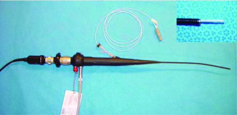
The endoscopic system consists of a Karl Storz Telecam NTSC camera system attached to a Karl Storz 11264BBU1 flexible hysteroscope. The hysteroscope was chosen for orbital application due to its small 3.5 mm tip diameter and 1.48 mm diameter working channel. Spatial localization is provided by the Northern Digital Aurora electromagnetic tracking system using a 1.3 mm diameter sensor with 6 degrees of freedom (DOF) that is inserted down the endoscope's working channel. A separate off-the-shelf 6 DOF pen probe tool was used for fiducial localization. The Aurora planar field generator is mounted on an adjustable articulated arm to facilitate the positioning of the target within the ideal working volume described by Atuegwu et al.18 The sensor was adhered to the tip of the scope to prevent rotation. In addition, its length was secured by a plastic clasp at the entry end in order to ensure that it remained in the same relative spatial relationship with the endoscope. The endoscope with the sensor protruding (prior to being fixed within the working channel) can be seen in Fig. 1. The endoscope was also attached to a Karl Storz 615 Xenon light source and a carbon dioxide insufflation pump to augment visualization in vivo. Video processing and display was performed by an Intel Core2 Duo machine running Windows 7 and equipped with a Euresys Piccolo frame grabber card.
FIG. 1.
Flexible endoscope with inserted magnetic tracker. The inset in the upper right corner shows the 1.3 mm diameter sensor slightly protruding from the working channel of the endoscope.
The ORION software system19 was used to facilitate image guidance. ORION is a flexible image-guided surgery software framework that allows various task-oriented modules to run simultaneously in accordance to the needs of the specific scenario, with four available windows for visual user interface. The transorbital surgery configuration consists of three preoperative image volume display windows arranged in orthogonal planes (sagittal, coronal, and transverse). A localization routine provides an initial opportunity to gather fiducial points while also constantly updating the system with the position of the 6 DOF sensor. Image-to-physical space registration is performed using the fiducial point set and an implementation of Horn's method,20 with the registered location of the tracked endoscope tip being displayed in all three image planes. A separate module updates the fourth window with the endoscopic video stream and performs the augmentation computations.
II.B. 3D/2D mapping
Augmented reality video systems fundamentally require a registration of 3D information to the 2D image plane. This registration was accomplished using the Direct Linear Transform (DLT) method,21 a mapping operation that provides the ability to accurately correlate points from the three-dimensional physical space of an operating room to pixels in the two-dimensional image space of the endoscopic video stream. The DLT is represented by the following equation:
| (1) |
where (x, y, z) is the three-dimensional point in physical space, (u, v) is the resulting point in two-dimensional space, w is a scaling factor, and A is the homogeneous transformation matrix (HTM). The equation uses homogeneous coordinates since it deals with projective space calculations, therefore the HTM has 11 independent elements and a34 is set equal to 1. The other parameters in the HTM represent the 11 degrees of freedom involved in the transformation from 3D space to 2D space, namely three translations, three rotations, source-to-image distance, the intersection point of the imaging plane and optical axis, and scaling factors in the u and v directions.
An HTM for a projection from 3D physical space into a particular 2D image space must be calculated using a known set of corresponding points, specifically,
where n is the size of the set of points. Expanding Eq. (1) yields an expression for w:
| (2) |
Substituting for w, u, and v can be expressed as
| (3) |
| (4) |
Expanding Eqs. (3) and (4) for a set of corresponding points in 2D and 3D of size n results in
| (5) |
Calibration, described in detail in Sec. II D, consists of gathering set of corresponding point coordinates in both 2D and 3D space, populating Eq. (2) with the values, and solving for the vector a using the pseudo-inverse of the 11 × N matrix. The vector a is then reconstituted as the HTM.
For any 3D point (x, y, z), w can be solved with Eq. (2), and the resulting mapped point in 2D space (u, v) is determined with Eqs. (3) and (4). This 3D point can be the location of tracked tools in physical space or the position of targets or segmented structures from a preoperative medical image volume, assuming an accurate registration from image space to physical space. In this application of video augmentation, we are interested overlaying the position of a known target in a preoperative CT scan onto the endoscopic video in real-time in order to enhance guidance and improve spatial awareness in a visually occluded environment.
II.C. Lens distortion correction
Lens distortion is a known feature of endoscopic images. The approximately radial effect can appreciably compromise user perception of depth, size, and structure. With practice and experience, human operators may be able to adapt to the distortion in order to perform their given medical tasks, whether it be minimally invasive interventions or exploratory diagnosis. However, the effect has particularly relevant impact in the context of computer vision, specifically for video augmentation capabilities, as error is introduced if the camera model is assumed to be undistorted.22
Improvements in endoscope optics on the manufacturer's end can lessen the degree of radial distortion but not fully correct it. As such, it is necessary to rectify the images in software prior to them being displayed. The process of intrinsic camera calibration involves generating a model of the distortion and subsequently using it to warp the camera output. The models are often developed using calibration images of checkerboard or grid patterns with known sizes and dimensions. One of the most popular means of camera calibration is Bouguet's toolbox for Matlab,23 which utilizes methods developed by Zhang24 and Heikkil and Silven25 within a straightforward user interface for comprehensive camera parameter calculation and optimization. Several other solutions have been developed for intrinsic camera calibration, with emphasis on automatic techniques26 and minimizing calibration images.27 These solutions offer advantages when camera calibration represents a major workflow bottleneck, which is particularly relevant in clinical systems where ease-of-use and time efficiency have considerable financial repercussions. However, most require high quality calibration images to converge. The small scale of the orbit and its internal soft tissue structures, along with the need to navigate around the eye ball, require any transorbital interventional endoscope to be both flexible and have a small diameter. The Karl Storz 11264BBU1 endoscope used in this experiment produces relatively low resolution images, and thus the more sophisticated correction techniques were not appropriate.
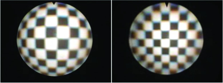
A series of 18 images of a black and white checkerboard pattern with known dimensions were taken at various angles and distances from the endoscope tip. Bouguet's toolbox was used to find the corners of each square in the checkerboard images, often with manual corrections, and subsequently generate the intrinsic camera parameters, namely the focal length, principal point, and image distortion coefficients. These parameters were implemented with OpenCV functions28 to rectify each new image frame from the endoscope as they are displayed by the ORION module. Figure 2 shows a distorted and corrected checkerboard image.
FIG. 2.
Distorted (left) and corrected (right) checkerboard image.
II.D. Calibration procedure
It is desirable to represent a large portion of the conical projection volume in the range of this transformation since structures of interest may be out of direct line of sight of the camera due to the presence of intermediary objects. As such, calibration of the HTM using Eq. (5) was performed with a set of 3D points (x,y,z)n that sampled a volumetric region of interest roughly the size of a human orbit at various depths, with corresponding 2D points (u,v)n to characterize the endoscopic video output. The 2D calibration points were collected from endoscopic video images that had already undergone lens distortion correction as described in Sec. II C.
For calibration, the base and tip of the endoscope were fixed on an immobile stand to ensure a constant position of the magnetically tracked sensor within the tip. A phantom containing 13 points in an approximate alternating-row grid arrangement was then placed in front of the endoscope tip. The Aurora field generator was positioned such that the endoscope tip and the phantom were within its optimal working volume. Each point of the phantom consisted of a colored indentation such that they could be easily localized in physical space using the Aurora pen probe without it slipping, and be easily annotated in image space due to the color difference from the background.
Starting with a phantom distance of approximately 1 cm from the endoscope tip, an endoscope image of the phantom points was taken and their 3D positions were collected using the Aurora probe. The phantom was then moved back from the tip by approximately 1 cm, and the procedure was repeated. The phantom was replaced with a larger version after the approximate 3 cm distance mark to maintain sampling of the edges of the endoscope image. A total of 91 calibration points were collected, at seven different phantom distances from the endoscope tip.
The 3D coordinates of each calibration point were transformed with respect to the position of the fixed magnetic sensor within the tip, such that the tip was considered to be the origin. This allows the HTM to remain valid throughout endoscope movement and rotation, so long as the transformed 3D point of interest is converted to the tracked tip's coordinate system. The 2D calibration point coordinates were annotated manually. The resulting set of points was used to populate Eq. (5) and calculate the HTM.
The integrity of the calibration was tested by running every 3D calibration point through the determined HTM and comparing the distance between the calculated 2D point and the actual 2D calibration point. This distance was designated as the calibration error. A mm/pixel ratio was calculated for each phantom position using the width of the central colored indentation in millimeters and the width of the same indentation in pixels for the endoscope image of that given position. Using these ratios, the average distance calibration error across the set of 91 points was found to be 0.395 mm.
II.E. Phantom preparation
Performance validation of transorbital interventional systems is particularly challenging due to the intricate, small-scale anatomy of the target region. Any model of the orbit to be used for surgical testing must adhere to a few basic principles. First, the proportions of the region must be similar to human anatomy. Second, the spatial obstacles present when accessing the retrobulbar space must be maintained. Lastly, the visual field of the endoscope must be occluded. We have previously developed a phantom to conform to these restrictions,10 and a modified version is presented below.
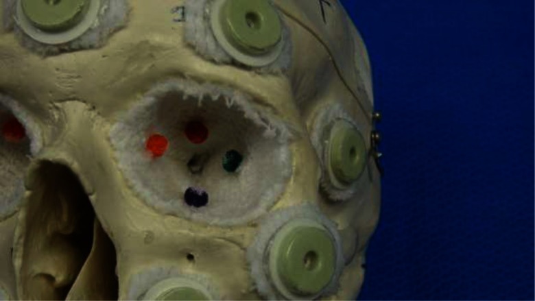
Four skull phantoms were built for the purpose of this experiment. Each consisted of a different commercially available, anatomically correct plastic skull model from CWI Medical. A total of ten radiographic skin fiducial markers were placed on each skull, with care taken to surround each orbit. The interior of each orbit was thinly padded to ensure that the contents would not spill out of the various fissures and openings present in the modeled bone. Four small, differently colored stellate balls were attached to the orbital wall deep within the retrobulbar space, one of which was previously soaked in a barium solution in order to appear bright on a CT scan. The presence or absence of barium was indistinguishable upon visual inspection. The barium ball was designated as the target, while the others were to serve as distracters. The color of the target ball for each orbit was recorded by the investigator. Figure 3 shows an example orbit with the attached balls.
FIG. 3.
Phantom orbit with attached colored stellate balls.
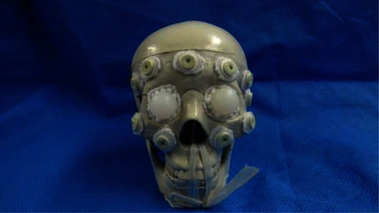
Realistically proportioned silicone rubber spheres were attached to nylon cords and fixed within the optic canal, simulating the human eyeballs and optic nerves and presenting the physician with spatial obstacles. The remaining intraorbital space was then filled with white polystyrene foam beads. These small beads would mimic fat tissue upon insertion of the endoscope by separating with a light application of force, but still occluding the visual environment to the operator. A complete skull phantom can be seen in Fig. 4. The skulls were securely mounted with an angled stand such that when the base of the mount was clamped to a table, the phantom was positioned to mimic a supine patient. Computed tomography (CT) scans were taken of each skull phantom, and the locations of the fiducial markers and the barium-soaked stellate balls were manually annotated in the image volume and recorded for use by the guidance system.
FIG. 4.
Complete skull phantom.
II.F. Experiment protocol
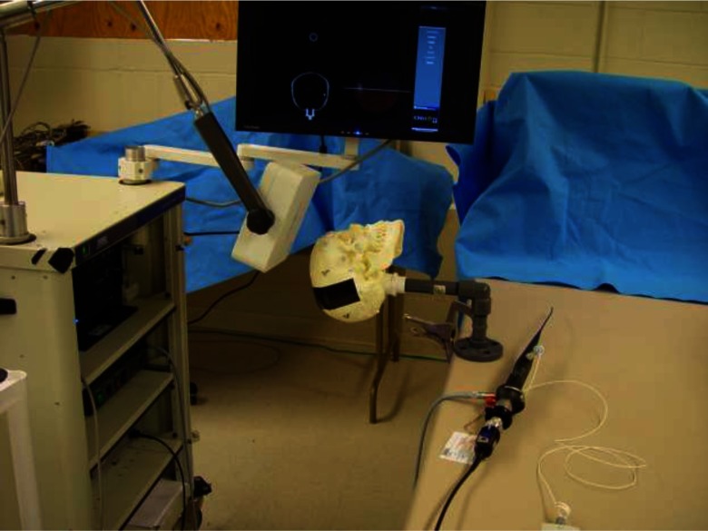
A given skull phantom was securely clamped to an immobile table with the Aurora field generator positioned near the crown of the head such that both orbits were within its optimal detection volume. The ten fiducial markers surrounding the orbits were spatially localized with the Aurora pen probe and registered to their previously manually annotated image-space counterparts using Horn's method.20 Average fiducial registration error was between 0.5 and 1.5 mm for each skull. Figure 5 shows a skull phantom in an appropriate experimental configuration.
FIG. 5.
Skull phantom in experimental configuration.
A total of 16 surgeons volunteered their time to assist in this experiment. This group included attendings, fellows, and residents from the surgical departments of ophthalmology, otolaryngology, gastroenterology, gynecology, and urology. Most had substantial experience with minimally invasive surgery and endoscopy.
While the skull phantom was being registered and the appropriate ORION displays were being set up, the surgeon would reference the preoperative CT scans of the phantom, note the relative locations of the target stellate balls, and formulate a navigation plan. After these preparation tasks were completed, the surgeon would take position next to the skull phantom, indicate readiness, insert the endoscope, and then perform the navigation task. A timer was started upon surgeon indication of readiness and ended upon declaration of target identity. The recorded metrics for each orbit was target identification accuracy (whether or not the surgeon correctly identified the barium-soaked ball by color) and procedure time. An orbital procedure was halted and declared to be an inaccurate identification if the surgeon had not declared a target by the 2 min mark.
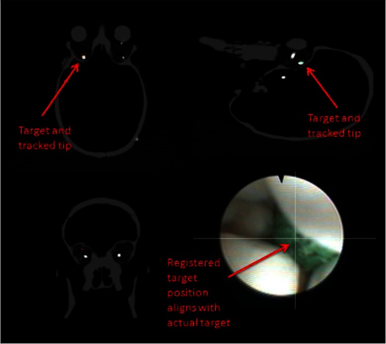
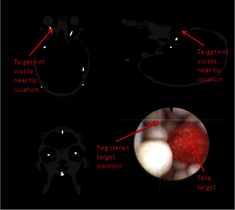
An example ORION display screenshot for an accurate target identification can be seen in Fig. 6. Note that the video augmentation points to the position of the target ball, which is verified by the appearance of the target in the orthogonal image planes. Figure 7 demonstrates the discovery of a nontarget colored ball. The augmentation clearly indicates that the real target is elsewhere, while the bright spot in the CT scan is not present.
FIG. 6.
Correct target identification with video augmentation. The radio-opaque ball can be seen in the sagittal and transverse slices as the round bright spot. The small boxes in the CT images represent the registered position of the endoscope tip. The intersected lines on the endoscopic video frame indicate the location of the target.
FIG. 7.
Incorrect target identification with video augmentation. The intersecting lines in the endoscopic video frame indicate that this colored ball is not the target, while there is no radio-opaque object near the registered endoscope tip on the CT images.
For each skull, one orbital procedure was performed with video augmentation while the other was performed without it, in random order. Augmentation was implemented as a simple pair of lines overlaying the video feed and intersecting at the 2D target location as determined by the HTM. The presence or absence of this display component was the only difference between augmented and unaugmented procedures. Upon completion of both orbital procedures in the first skull, the process was repeated for the three additional skulls. The entire experiment took approximately 30 min to complete for each surgeon.
III. RESULTS
With 16 surgeons performing eight orbital interventions each, there were a total of 128 data points, 64 using the augmented video and 64 using the basic guidance system. The barium-soaked stellate ball target was correctly identified with 95.3% accuracy using augmented video and 85.9% accuracy without it. This represents an augmented miss rate of approximately 1/3 of the unaugmented miss rate. It could be expected that the first skull phantom tested would skew the data somewhat due to surgeon unfamiliarity with the procedure. However, if the data from the first skull phantom is removed, the augmented and unaugmented accuracies demonstrate little change, with values of 95.8% and 85.4%, respectively.
Only procedure times from phantom experiments where the target was successfully identified were considered for analysis. The average procedure times for the augmented and unaugmented interventions were 18.3 and 23.9 s, respectively, with standard deviations of 11.3 and 15.4. As this data set was not normally distributed, a two independent sample Wilcoxon rank-sum test (Mann-Whitney U test) was performed to determine the effect of augmentation on procedure time tendencies. The results indicated that the two groups were significantly different (Z = −2.044, p = 0.041), with augmentation tending to result in faster procedure times (p = 0.020).
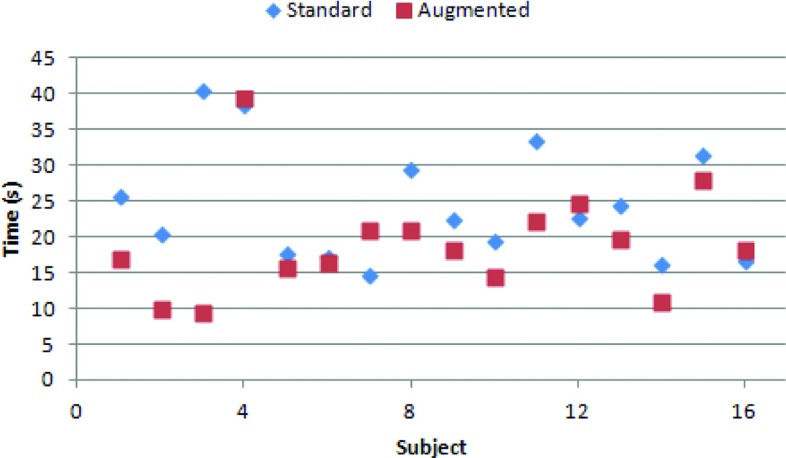
To account for interoperator variability, mean augmented and unaugmented procedure time was computed for each surgeon. These means can be seen in Fig. 8. The resulting population of 32 means satisfied the chi-square goodness-of-fit test for a normal distribution and was thus analyzed with a two-sided paired sample t-test. The test indicated a significant difference in procedure time between the augmented (mean = 19.2) and standard (mean = 24.5) guidance system (T = −2.526, p = 0.023). If the data are not considered normal, the two paired sample Wilcoxon signed-rank test also indicated significant difference between the two groups (Z = 2.456, p = 0.014).
FIG. 8.
Intrasurgeon mean times. The mean augmented time for each surgeon tends to be lower than their unaugmented time.
IV. DISCUSSION
It is important to be aware of the characteristics of orbital surgery when making any judgment about the system performance. The orbit is a very small space, and thus finding an interior object without direct visualization should theoretically not take a large amount of time. However, the risk of causing severe impairment to a human patient is quite real if a mistake is made, necessitating a high degree of caution and steadiness for any transorbital intervention in a live subject. This scenario is extremely difficult to replicate in anthropomorphic phantom model experiments. While surgeons were encouraged to proceed as if they were operating on a live subject, it was clear to the investigator that this was not always the case, particularly if the target was not found after the first insertion of the endoscope. Since the phantom is fundamentally immune to harm, it is inevitable that the primary goal of the operator is to find the target, as opposed to avoiding imagined negative effects to the patient.
This effect is further exacerbated by the limited realism in phantom construction. While measures were taken to provide substitute materials for the optic nerve, eye ball, and fat tissue, the extraocular muscles were not modeled due to their particularly complex arrangement. As such, the orbit and optic nerve were substantially more mobile than would be allowed in human case, as the attached muscles would hold them in place more securely. The absence of muscles also eliminated a noteworthy structural obstacle in transorbital surgery; while endoscope impact with the muscles is not as critical as reckless optic nerve contact, they take up a considerable volume of orbital space and navigation must be planned accordingly. Furthermore, the polystyrene beads used to model fat would occasionally pack together and inhibit endoscope movement. This was particularly evident in the augmented cases, where the surgeon would attempt to drive the scope straight forward as indicated by the intersecting target lines, but would be unable to move a polystyrene bead out of the way. In these cases, the guidance system and augmentation clearly indicated that the target was directly beyond the bead, but visual confirmation was impossible and another route had to be taken. Finally, the targets were embedded on the walls deep within the orbit and not suspended in the interior retrobulbar space, as this would be particularly difficult to implement without them substantially moving position and rending the preoperative imaging scan useless.
Despite the inability of the phantom to encompass all of the anatomical intricacies of the human orbit, it still provided a realistically proportioned working space, modeled the primary obstacle of navigating around the eye ball, and exhibited the characteristic endoscopic visual occlusion of fat tissue. While each surgeon performed the task with different degrees of delicacy, they were consistent in their approach for all trials, as the investigator did not instruct them to change behavior after the initial explanation of the experiment.
In light of these experimental limitations, we are encouraged by the results. The implementation of video augmentation had a clearly positive impact on transorbital procedures performed in skull phantoms. The measured results quantitatively indicate that video augmentation improves the accuracy of target identification, while also decreasing the procedure time for successful navigations. This outcome has important clinical value. Considering the delicate nature of the optic nerve, any therapeutic intervention must be precisely guided and controlled, minimizing harm to the surrounding tissue while successfully completing the given task. These expectations are reliant on a highly accurate targeted navigation.
When considering the difference in navigation times in terms of raw seconds, the improvement from standard to augmented may not seem particularly impactful, with a mean difference of 5.6 s. However, faster procedure times with statistically significant consistency are indicative of a superior sense of surgeon orientation within the operational space, as well as a higher degree of comfort with the tools and task. Given the aforementioned limitations of the skull phantoms, particularly the obstructive effect of the polystyrene beads, it is not unreasonable to expect a greater time difference under more realistic conditions.
While the implementation of video augmentation in this experiment was limited to a simple indication of the direction to a target, the mapping of 3D space to 2D space allows for the incorporation of much more sophisticated visualization displays. Such possibilities include nonlinear preoperatively planned surgical paths and overlaid soft tissue structures, using 3D points generated from existing orbital soft tissue image segmentation algorithms.29,30 So long as care is taken to avoid overwhelming the display with extraneous visual information by constantly obtaining surgeon feedback, this technology could considerably simplify retrobulbar access and enable safe, repetitive therapeutic interventions.
V. CONCLUSIONS
The delicate anatomy of the orbital space requires any intervention to be precise and clearly directed, with minimal superfluous motion to avoid inflicting damage to the patient. While standard image guidance provides critical information regarding instrument location and surrounding anatomy, the typical interface of three orthogonal image planes leaves an awareness gap in terms of orientation and trajectory, particularly when the endoscopic viewing field is occluded by blood or tissue. This additional information can be provided with video augmentation. In this series of anthropomorphic phantom experiments, we have demonstrated that both target identification accuracy and interventional procedure time are improved when image guidance is used in conjunction with video augmentation.
ACKNOWLEDGMENTS
The authors would like to thank the various physicians who volunteered their time for this experiment, Dahl Irvine and the Vanderbilt CT technicians for their help with imaging, and Tom Pheiffer, Yifei Wu, and Rebekah Conley for their assistance with calibrations. This work was supported in part by the Research to Prevent Blindness Physician Scientist Award, the Unrestricted Grant from Research to Prevent Blindness to the Vanderbilt Eye Institute, and the National Institutes of Health under Grant R21 RR025806.
REFERENCES
- 1.McKinnon S. J., Goldberg L. D., Peeples P., Walt J. G., and Bramley T. J., “Current management of glaucoma and the need for complete therapy,” Am. J. Manag. Care 4, S20–S27 (2008). [PubMed] [Google Scholar]
- 2.Levin L. A. and Peeples P., “History of neuroprotection and rationale as a therapy for glaucoma,” Am. J. Manag. Care 14, S11–S14 (2008). [PubMed] [Google Scholar]
- 3.Prabhakaran V. C. and Selva D., “Orbital endoscopic surgery,” Indian J. Ophthalmol. 56, 5–8 (2008). 10.4103/0301-4738.37587 [DOI] [PMC free article] [PubMed] [Google Scholar]
- 4.Pham A. M. and Strong E. B., “Endoscopic management of facial fractures,” Curr. Opin. Otolaryngol. Head Neck Surg. 14, 234–241 (2006). 10.1097/01.moo.0000233593.84175.6e [DOI] [PubMed] [Google Scholar]
- 5.Kasperbauer J. L. and Hinkley L., “Endoscopic orbital decompression for Graves′ ophthalmopathy,” Am. J. Rhinol. 19, 603–606 (2005). [PubMed] [Google Scholar]
- 6.Kuppersmith R. B., Alford E., Patrinely J. R., Lee A. G., Parke R. B., and Holds J. B., “Combined transconjunctival/intranasal endoscopic approach to the optic canal in traumatic optic neuropathy,” Laryngoscope 107, 311–315 (1997). 10.1097/00005537-199703000-00006 [DOI] [PubMed] [Google Scholar]
- 7.Balakrishnan K. and Moe K. S., “Applications and outcomes of orbital and transorbital endoscopic surgery,” Otolaryngol. Head Neck Surg. 144, 815–820 (2011). 10.1177/0194599810397285 [DOI] [PubMed] [Google Scholar]
- 8.Mawn L. A., Shen J.-H., Jordan D. R., and Joos K. M., “Development of an orbital endoscope for use with the free electron laser,” Ophthal. Plast. Reconstr. Surg. 20, 150–157 (2004). 10.1097/01.IOP.0000117342.67196.16 [DOI] [PubMed] [Google Scholar]
- 9.Atuegwu N. C., Mawn L. A., and Galloway R. L., “Transorbital endoscopic image guidance,” Proc. Eng. Med. Biol. Soc. Annu. 27, 4663–4666 (2007). 10.1109/IEMBS.2007.4353380 [DOI] [PubMed] [Google Scholar]
- 10.Ingram M.-C., Atuegwu N., Mawn L. A., and Galloway R. L., “Transorbital therapy delivery: Phantom testing,” SPIE Medical Imaging 7964, 79642A (2011). 10.1117/12.877095 [DOI] [Google Scholar]
- 11.Sielhorst T., Feuerstein M., and Navab N., “Advanced medical displayers: A literature review of augmented reality,” IEEE J. Disp. Tech. 4, 451–467 (2008). 10.1109/JDT.2008.2001575 [DOI] [Google Scholar]
- 12.Shahidi R., Bax M. R., Maurer C. R., Johnson J. A., Wilkinson E. P., Wang B., West J. B., Citardi M. J., Manwaring K. H., and Khadem R., “Implementation, calibration, and accuracy testing of an image-enhanced endoscopy system,” IEEE Trans. Med. Imaging 21, 1524–1535 (2002). 10.1109/TMI.2002.806597 [DOI] [PubMed] [Google Scholar]
- 13.Lapeer R., Chen M. S., Gonzalez G., Linney A., and Alusi G., “Image-enhanced surgical navigation for endoscopic sinus surgery: Evaluating calibration, registration, and tracking,” Int. J. Med. Robot. Comp. 4, 32–45 (2008). 10.1002/rcs.175 [DOI] [PubMed] [Google Scholar]
- 14.Kawamata T., Iseki H., Shibasaki T., and Hori T., “Endoscopic augmented reality navigation system for endonasal transsphenoidal surgery to treat pituitary tumors: Technical note,” Neurosurgery 50, 1393–1397 (2002). [DOI] [PubMed] [Google Scholar]
- 15.Liu W. P., Mirota D. J., Uneri A., Otake Y., Hager G., Reh D. D., Ishii M., Gallia G. L., and Siewerdsen J. H., “A clinical pilot study of a modular video-CT augmentation system for image-guided skull base surgery,” SPIE Medical Imaging 8316, 831633 (2012). 10.1117/12.911724 [DOI] [PMC free article] [PubMed] [Google Scholar]
- 16.Stefansic J. D., Herline A. J., Shyr Y., Chapman W. C., Fitzpatrick J. M., Dawant B. M., and Galloway R. L., “Registration of physical space to laparoscopic image space for use in minimally invasive hepatic surgery,” IEEE Trans. Med. Imaging 19, 1012–1023 (2000). 10.1109/42.887616 [DOI] [PubMed] [Google Scholar]
- 17.DeLisi M. P., Mawn L. A., and Galloway R. L., “Transorbital target localization in the porcine model,” SPIE Medical Imaging 8671, 86711S (2013). 10.1117/12.2007943 [DOI] [Google Scholar]
- 18.Atuegwu N. C. and Galloway R. L., “Volumetric characterization of the aurora magnetic tracker system for image-guided transorbital endoscopic procedures,” Phys. Med. Biol. 53, 4355–4368 (2008). 10.1088/0031-9155/53/16/009 [DOI] [PubMed] [Google Scholar]
- 19.Stefansic J. D., Bass W. A., Hartmann S. L., Beasley R. A., Sinha T. K., Cash D. M., Herline A. J., and Galloway R. L., “Design and implementation of a PC-based image-guided surgical system,” Comput. Methods Prog. Biomed. 69, 211–224 (2002). 10.1016/S0169-2607(01)00192-4 [DOI] [PubMed] [Google Scholar]
- 20.Horn B. K. P., “Close-form solution of absolute orientation using unit quaternions,” J. Opt. Soc. Am. A 4, 629–642 (1987). 10.1364/JOSAA.4.000629 [DOI] [Google Scholar]
- 21.Adbel-Aziz Y. I. and Karara H. M., “Direct linear transformation from comparator coordinates into object space coordinates in close range photogrammetry,” Proceedings of Symposium on Close-Range Photogrammetry (Univ. of Illinois at Urbana-Champaign, Urbana, IL, 1971), pp. 1–18 [Google Scholar]
- 22.Khadem R., Bax M. R., Johnson J. A., Wilkinson E. P., and Shahidi R., “Endoscope calibration and accuracy testing for 3d/2d image registration,” in Medical Imaging Computing and Computer-Assisted Intervention (MICCAI) 2001 (Springer, Berlin, 2001), pp. 1361–1362 [Google Scholar]
- 23.Bouguet J.-Y., Camera Calibration Toolbox for Matlab (2004) (available URL: http://www.vision.caltech.edu/bouguetj/calib_doc/index.html).
- 24.Zhang Z., “Flexible camera calibration by viewing a plane from unknown orientations,” Proceedings of 7th IEEE International Conference on Computer Vision (IEEE, Kerkyra, 1999), pp. 666–673 [Google Scholar]
- 25.Heikkil J. and Silven O., “A four-step camera calibration procedure with implicit image correction,” Procof the IEEE Computer Society Conference on Computer Vision and Pattern Recognition 1997 (IEEE, San Juan, 1997), pp. 1106–1112 [Google Scholar]
- 26.Wengert C., Reeff M., Cattin P., and Székely G., “Fully automatic endoscope calibration for intraoperative use,” Bildverarbeitung für die Medizin 2006 (Springer, Berlin, 2006), pp. 419–423 [Google Scholar]
- 27.Melo R., Barreto J. P., and Falcao G., “A new solution for camera calibration and real-time image distortion correction in medical endoscopy - Initiate technical evaluation,” IEEE Trans. Biomed. Eng. 59, 634–644 (2012). 10.1109/TBME.2011.2177268 [DOI] [PubMed] [Google Scholar]
- 28.Bradski G. and Kaehler A., “Learning OpenCV: Computer vision with the OpenCV library,” O'Reilly Media, Inc. (2008).
- 29.Asman A. J., DeLisi M. P., Mawn L. A., Galloway R. L., and Landman B. A., “Robust non-local multi-atlas segmentation of the optic nerve,” SPIE Medical Imaging 8669, 86691L (2013). 10.1117/12.2007015 [DOI] [PMC free article] [PubMed] [Google Scholar]
- 30.Noble J. H. and Dawant B. M., “An atlas-navigated optimal medial axis and deformable model algorithm (NOMAD) for the segmentation of the optic nerves and chiasm in MR and CT images,” Med. Image Anal. 15, 877–884 (2011). 10.1016/j.media.2011.05.001 [DOI] [PMC free article] [PubMed] [Google Scholar]


