Abstract
DLC-type layers offer a good potential for application in medicine, due to their excellent tribological properties, chemical resistance, and bio-inert character. The presented study has verified the possibility of alloying DLC layers with titanium, with coatings containing three levels of titanium concentration prepared. Titanium was present on the surface mainly in the form of oxides. Its increasing concentration led to increased presence of titanium carbide as well. The behavior of the studied systems was stable during exposure in a physiological saline solution. Electrochemical impedance spectra practically did not change with time. Alloying, however, changed the electrochemical behavior of coated systems in a significant way: from inert surface mediating only exchange reactions of the environment in the case of unalloyed DLC layers to a response corresponding rather to a passive surface in the case of alloyed specimens. The effect of DLC layers alloying with titanium was tested by the interaction with a simulated body fluid, during which precipitation of a compound containing calcium and phosphorus - basic components of the bone apatite - occurred on all doped specimens, in contrast to pure DLC. The results of the specimens' surface colonization with cells test proved the positive effect of titanium in the case of specimens with a medium and highest content of this element.
Keywords: EIS, XPS, bioactivity, corrosion, titanium doped DLC
Introduction
DLC (diamond-like carbon) layers excel in high hardness, chemical resistance and good tribological properties.1 It is not only these properties that predetermine them for use in human medicine.2-6 In principle, there are two ways of their application: their tribological properties may be employed on articulating pairs of small and big joints replacements, and they may be also applied, in an entirely different way, on implants made of materials which may cause a negative response of the organism (e.g., alloys containing nickel, cobalt, chromium, vanadium etc.). In the latter case they serve as bio-inert barrier layers capable of eliminating the adverse corrosion process associated with the release of soluble corrosion products into the body environment.7
One of the current major aims in the field of implantology is to achieve the fastest possible osseointegration, which requires application of implants with a bio-active (-activated) surface. In order to meet this requirement it is necessary to modify the properties of the surface of bio-inert DLC coatings to make sure that they are actively accepted by the body, and that their tribological properties are preserved at the same time. The layers’ doping with titanium, zirconium, niobium and other elements represents a possible treatment increasing their biological behavior.4,8-19 It is known that the biological response of titanium, which is in principle bioactive to a certain extent, can be chemically modified.20
The presented work is based on the hypothesis that alloying DLC with titanium could result in bioactivation of DLC with further treatment leading to an increase of potential bioactivity. The work was focused on preparing Ti-DLC layers doped with titanium (Ti:C-H) at three concentration levels, and on the study of these layers’ interaction with a physiological saline solution and a simulated body fluid. Evaluation of the surface colonization with cells was part of the study.
Results and Discussion
The coatings structure was Ti/gradient Ti-C:H/Ti-C:H, with the titanium interlayer thickness being 0.4–0.5 µm in all cases. The total thickness of the A, B and C specimens coatings (Table 1) was 1.4 µm with a functional layer of 0.6 µm, 1.6 µm with a functional layer of 0.8 µm, and 1.5 μm with a functional layer of 0.8 µm of the value, respectively. In all cases, a layer with a flat profile of titanium concentration was formed. The typical course of carbon, titanium and aluminum gradients in the layer, determined by the GDS method, is illustrated in Figure 1. The values of the layers thickness, determined using this method, were in good agreement with the values obtained from the calotest measurements. In all cases the coating adhesion was broken in the course of the scratch test at a critical load of 30 N. In this respect the layers met the prerequisites for real application. The adjustment of technological conditions allowed for doping the DLC layer with titanium at three levels and a relatively broad concentration range. In the case of layers with the lowest level of alloying, the technological process in the given arrangement was on the border of stability. The deposition of higher-alloyed coatings was without any problems in terms of technology.
Table 1. Composition of Ti-a:CH A, B and C specimens’ surface in as-prepared state.
| sample | A | B | C |
|---|---|---|---|
| cTi [% at.] | 3.4 | 10.2 | 23.6 |
| cC [% at.] | 96.6 | 89.8 | 76.4 |
| TiC/Ti (C1s) | 0.01 | 0.09 | 0.23 |
| TiC/Ti (Ti2p) | 0.03 | 0.10 | 0.31 |
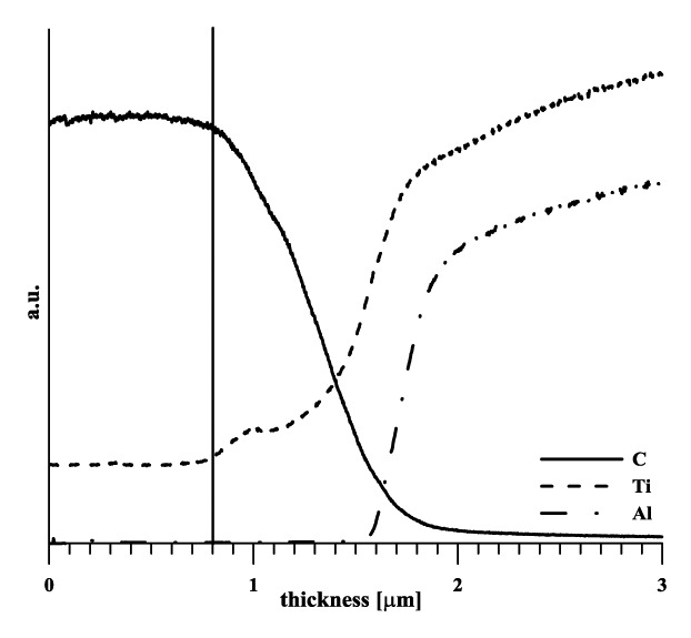
Figure 1. Profile of carbon, titanium and aluminum concentration-specimen B (signal not quantified)
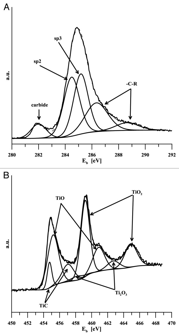
Given the layers thickness, it was not possible to determine titanium content using e.g., the standard SEM EDS analysis. This method provides integral information based on the micro-volume analysis, the depth of the analyzed material is at the level of micrometers. Consequently, the results obtained in our case were affected by both the gradient transition region and the basic material. Interaction with the body environment is based on the state of the surface in terms of both its composition and the binding state of its components. Titanium should be available on the alloyed DLC layer – body environment interphase in the same form as on the titanium metal surface, i.e., bound in oxides. This should prepare conditions for active interaction with the body environment and for possible chemical bio-activation just like in the case of titanium implants. Titanium is highly reactive and in reaction with carbon forms stable carbide (ΔGof = -180.438 kJ/mol21). This fact aroused concern that all titanium in DLC might be carbide-bound and thus probably bio-inert. For this reason the analyses of both the chemical composition and binding state were conducted using photoelectron spectroscopy. Titanium carbide content in the layers was determined from the signal of carbon (C 1s) and titanium (Ti 2p), and it is shown in Table 1. The Xray diffraction method provided a qualitative proof of the presence of carbide TiC in specimens with medium and highest titanium content (B and C). Binding energy of C1s in TiC can be found between 281.5–281.7 eV,22 281.7 eV.23 Binding energies of the Ti 2p doublet for titanium bound in TiC is 454.7 eV (2 p3/2) and 458.2 eV (2 p1/2).24 Photoelectron spectra of C1s and Ti2p are given in Figure 2 and Figure 3. While only an indication of a carbide peak can be seen in the specimen with the lowest carbon content, carbon presence is clearly evident in both of the other two specimens. Titanium content in various binding states is determined based on the analysis of high-resolution carbon and titanium spectra, C1s and Ti2p respectively (Fig. 4). In the latter case, the regions of carbide-bound titanium and of titanium/titanium bound in oxides overlap. Consequently, determination of TiC content from these spectra is rather problematic. It was assumed that the C1s peak analysis should provide more unambiguous results. Table 1 implies that the amount of titanium in TiC as determined by the analysis of both types of spectral lines (C1s and Ti2p) differs significantly only in the case of the specimen with the highest level of alloying. Based on the above facts it may be assumed that the value of 23% is closer to reality. Ratio of titanium oxides was
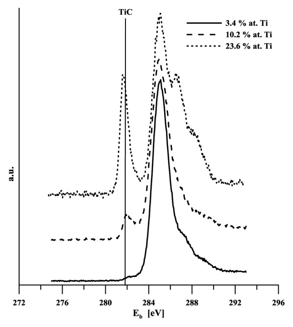
Figure 2. XPS C1s spectra of titanium doped DLC layers
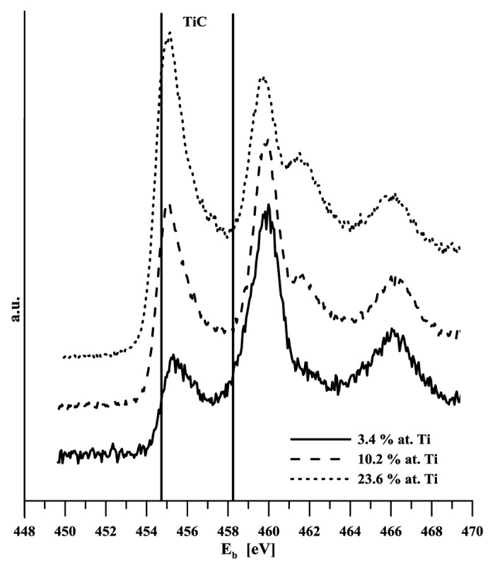
Figure 3. XPS Ti 2p spectra of titanium doped DLC layers
Figure 4. Detailed analysis of the Ti-a:CH specimen B photoelectron spectra (A) C1s (B) Ti2p
Electrochemical impedance spectra provide detailed information about materials’ interaction with the environment. Figure 5 shows Bode presentations of EIS spectra of an unalloyed DLC layer, specimen B, and cp titanium in a physiological solution. The course of dependencies (the spectra shown in Figure 5 were measured in the 24th and 336th hour of exposure) makes it clear that the behavior of all materials was stable, with the spectra showing only a minimum change through the course of exposure. The impedance response of titanium corresponds to the passive state of this material. The spectra of coated specimens were affected by the presence of more phase boundaries (time constants). This behavior was an expectable response of the layered structures.
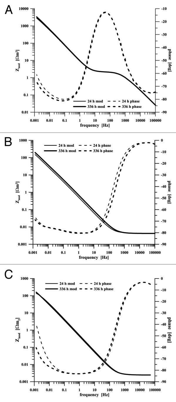
Figure 5. EIS spectra of specimens exposed in a physiological saline solution (A) non-doped DLC layer (B) Ti-a:CH sample B, (C) titanium
The spectrum of the DLC layer deposited on a polished surface in principle reflects the behavior of inert graphite – assuming the absence of pores passing through the surface to the interlayer. The oxidation-reduction reaction of oxygen represents the only process linked with the charge transfer in this case. The course of the spectrum at frequencies above 0.5 kHz is influenced by adsorption processes.25 The DLC layer doping with titanium caused an essential change in the electrochemical behavior, with impedance spectra being comparable rather with dependencies measured on titanium (Fig. 5C). Due to its presence in the DLC layer, the slower electrode processes on graphite are overlapped by titanium interaction with the environment on the Ti-C:H phase boundary. The course change at frequencies above 0.5 kHz is missing in the spectra while, on the contrary, the low phase angle region is largely expanded, to roughly three orders of frequency, indicating a more significant surface capacitive behavior. The differences in the course of titanium spectra of non-doped and titanium-doped DLC coatings are given in Figure 5. The presence of titanium on the coatings surface is positive in terms of medical applications as it indicates a possible effect on bioactivity of the layer - body environment interphase. DLC coatings display bio-inert behavior, titanium oxides are active themselves to a certain extent,26,27 and the surface may be (bio-) activated by further chemical treatment.20,28-30
Exposure in a simulated body fluid represents one of the tests employed to evaluate surface bioactivity.31 During these tests, the state of specimens surface was periodically monitored using electrochemical impedance spectroscopy in our case. Its advantage rests in the information richness of the signal. The EIS spectrum bears in itself the response of processes and changes on individual phase boundaries (surface-layer, layer-electrolyte, etc.) which affect the course of electrochemical reactions. Compounds close to bone hydroxyapatite are very little soluble (e.g., Ks of hydroxyapatite is 2.91.10-58 32) and display a rather insulating character. Consequently, if they are precipitated in the course of the specimen exposure in a simulated body fluid, the presence of a new phase boundary should be detected by EIS. The results of measurements are summarized in Table 2 and Figure 6. The state of the surface after exposures was again evaluated using photoelectron spectroscopy. The relative ratio of calcium and phosphorus contents calculated from the atomic representation of these elements was 1.17 (sample A), 1.13 (sample B) and 1.05 (sample C). Signal of both elements was on the background level in the case of pure DLC. The presence of calcium and phosphorus was clearly detected on doped DLC layers but the ratio of these elements was always lower than what would correspond to hydroxyapatite.31,33-35 Precipitated layers were too thin for XRD analysis.
Table 2. Results of EIS spectra analysis of Ti-a:CH A, B and C samples exposed in a simulated body fluid.
| sample | DLC | A | B | C | |||||
|---|---|---|---|---|---|---|---|---|---|
| time | h | 24 | 336 | 24 | 336 | 24 | 336 | 24 | 336 |
| Rout | Ω.m2 | 10070 | 16700 | 1410 | 3750 | 785 | 2490 | 290 | 1060 |
| CPEout | S.sα/m2 | 35.5.10−3 | 33.1.10−3 | 197.10−3 | 147.10−3 | 361.10−3 | 234.10−3 | 1.19 | 0.547 |
| equivalent circuit | c | c | b | b | b | b | b | b | |
Figure 6.
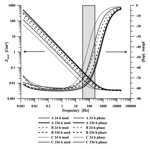
EIS spectra of titanium doped DLC layers exposed in a simulated body fluid
The electrochemical impedance spectra of all of the studied systems in the simulated body fluid as shown in Figure 6 were analyzed by equivalent circuits Figure 7B (doped layers) and Figure 7C (pure DLC layers). In all specimens, surface resistance Rout increased in the course of exposure. It corresponded to the charge transfer via phase boundary DLC-SBF or DLC (dopped Ti)-SBF. The value increased 1.7-times in the case of unalloyed specimens, 2.7-times for alloyed specimen A, and 3.2-times for specimen B. The resistance in the case of the specimen C increased 3.7-times. The CPE part of the unalloyed DLC layer – SBF phase boundary equivalent circuit (CPEdl) changed only minimally in the course of exposure, while having decreased in all other cases. Both the increase in Rout and decrease in the doped layers CPE corresponded to the formation and growth of the layer on the phase boundary with the electrolyte. The reason for the increasing surface resistance and relatively stable capacitance of this phase boundary in the system with a non-doped DLC layer is not quite clear.
Figure 7.

Equivalent circuits used in the EIS spectra analyses
The measurements established that electrochemical impedance spectroscopy is a useful tool for monitoring the interaction of biomaterials surface with an SBF solution, and that it may be used in the study of the kinetics of precipitation processes. In that respect, the region between 70 and 300 Hz seems to be of interest as it is this region where surface processes occur36-39 (Fig. 6). Both the spectra phase and module recorded for individual materials were significantly different in this frequency range.
The preliminary results of surface colonization with the MG63 cell culture measurement are summarized in Figure 7. Doping with titanium increased colonization significantly in the case of specimen B, the level was comparable with titanium. Increased colonization was also observed in the specimen C, even though it was less notable. These preliminary results were burdened with a relatively considerable variance in all cases.
Conclusions
The presented study proves that the adjustment of technological parameters allows for preparing DLC layers with a broad range of titanium concentrations. Titanium was present on the surface in the form of oxides, but its growing concentration led to higher occurrence of titanium carbide.
Alloying changed the electrochemical behavior of coated systems in a significant way – from an inert surface mediating only exchange reactions of the environment in the case of non-alloyed DLC layers to a response corresponding rather to a passive surface as seen in alloyed specimens. The behavior of the studied specimens was stable during exposure in the simplest model of a body environment – physiological saline solution.
The interaction with a simulated body fluid confirmed a positive effect of DLC doping with titanium. The presence of calcium and phosphorus as the basic components of the bone apatite was clearly proved in all doped specimens, in contrast to pure DLC. The cell test indicated a positive effect of titanium on surface colonization of Ti-a:CH samples B and C.
Materials and Methods
Flat substrates in the shape of a disc with a diameter of 14 mm and thickness of 3 mm made of Ti-6Al-4V alloy (ASTM B265 - 13a, Grade 23) were coated. Comparative electrochemical measurements on non-coated cp-titanium (ASTM B265 - 13a, Grade 1), and on Ti-6Al-4V alloy (ASTM B265 - 13a, Grade 5) coated with the DLC layer (a:C-H) were performed.
Prior to applying the coating system, the surface was polished to roughness of Ra = 0.08 μm. Coatings were deposited in a Hauzer Flexicoat 1200 device (configuration with five planar magnetrons, chamber volume 1000 L). The substrates were first degreased in an alkaline ultrasound bath, rinsed in deionized water and dried in vacuum. Once placed in the deposition chamber, the substrates’ surface was cleaned in argon plasma. The deposition itself started with formation of an adhesive inter-layer of pure Ti, followed by a gradient inter-layer with a composition changing from Ti to Ti-C:H. The adhesive inter-layer was deposited by means of non-equilibrium magnetron deposition from Ti (99.5%) targets in argon atmosphere (99.999%), with gradual addition of acetylene (99.6%). The functional Ti-C:H layer was deposited after achieving the specified acetylene flow. A bias of -200 V was applied on the substrates holder, the deposition temperature was 200 °C, the achieved limiting pressure was 2.10−3 Pa, and the deposition pressure was 0.8 Pa. The layer thickness was determined using the calotest method, adhesion to the coated substrate was measured by means of the scratch test (CSEM Revetest). The shape of titanium profile in the Ti:C-H layer was determined by an optical emission spectrometer with glow discharge excitation and a radiofrequency source (GDOES) GD Profiler II (Horiba Jobin Yvon).
Xray photoelectron spectra (XPS) spectra were measured using an EscaProbe P (Omicron) spectrometer with an excitation monochromatic Al Kα (E = 1486.6 eV) source. Survey spectra in the range of binding energies of 120–550 eV and high resolution spectra Ti 2p, C 1s, O 1s, P 2p and Ca 2p were scanned. Energy was normalized to the gold peak binding energy (Au 4f7/2 Eb = 83.98 eV22). Xray diffraction measurements were conducted using a X’Pert PRO (PANanalytical) device.
Prior to electrochemical measurement, the specimens were degreased and sterilized in a standard way (120 °C/20 min, sterilizer BMT Ecosteri). Exposure environments included a physiological saline solution (0.9 g/l NaCl) and a simulated body fluid (SBF).31 The oxygen content in the solutions was not regulated.
Measurements were done in a plastic exposure cell thermostated to 37 ± 0.2 °C using a water bath. A silver/silver chloride electrode (Ag/AgCl/KCl 3 mol/l, hereinafter abbreviated SSCE) was used as a reference electrode, with a large-area platinum gauze chosen as a counter-electrode. The specimens were exposed in the given medium for 336 h, with each specimen used only once. In the course of exposure, the open circuit potential and the impedance spectrum were measured at the given potential periodically each 24 h (range of frequencies 100 kHz to 1 mHz with an AC signal amplitude of 15 mV). All measurements were performed using Reference 600 potentiostat, equipped with an ECM8 multiplexer (Gamry). The EIS spectra were analyzed using equivalent circuits given in Figure 7. The impedance of the constant phase element (CPE) is defined as Z(ω) = Q−1(jω)-α, where the meaning of Z, ω and j is as usual. The constant phase element is used in modeling the spectra of non-homogeneous systems, if α = 1 the Q parameter has the meaning of capacitor. Equivalent circuit Figure 7A represents a simple phase boundary. Equivalent circuit Figure 7B is mostly used to analyze the spectra of the substrate material covered with a non-porous layer. The circuit Figure 7C contains an Rs-CPEs element describing adsorption processes.25
Specimens were sterilized prior to the test of colonization by cells. The MG 63 cell line cultivated in a minimal essential medium with 5% bovine fetal serum added was used for the measurements. The cells were inoculated directly to the surface of the studied material, the area occupied with the cells after 72 h of cultivation was evaluated. For this purpose, the cells on the surface were fixed and stained with Giemsa stain 10-times diluted with distilled water. The area occupied by the cells on the specimen surface was evaluated on ten picture fields as minimum.
References
- 1.Nalwa HS, ed. Handbook of Thin Film Materials, Volume 1. 2002. [Google Scholar]
- 2.Ma WJ, Ruys AJ, Mason RS, Martin PJ, Bendavid A, Liu Z, Ionescu M, Zreiqat H. DLC coatings: effects of physical and chemical properties on biological response. Biomaterials. 2007;28:1620–8. doi: 10.1016/j.biomaterials.2006.12.010. [DOI] [PubMed] [Google Scholar]
- 3.Roy RK, Lee K-R. Biomedical applications of diamond-like carbon coatings: a review. J Biomed Mater Res B Appl Biomater. 2007;83:72–84. doi: 10.1002/jbm.b.30768. [DOI] [PubMed] [Google Scholar]
- 4.Hauert R. A review of modified DLC coatings for biological applications. Diamond Related Materials. 2003;12:583–9. doi: 10.1016/S0925-9635(03)00081-5. [DOI] [Google Scholar]
- 5.Hauert R, Muller U. An overview on tailored tribological and biological behavior of diamond-like carbon. Diamond Related Materials. 2003;12:171–7. doi: 10.1016/S0925-9635(03)00019-0. [DOI] [Google Scholar]
- 6.Grill A. Diamond-like carbon coatings as biocompatible materials - an overview. Diamond Related Materials. 2003;12:166–70. doi: 10.1016/S0925-9635(03)00018-9. [DOI] [Google Scholar]
- 7.Cheng Y, Zheng YF. The corrosion behavior and hemocompatibility of TiNi alloys coated with DLC by plasma based ion implantation. Surf Coat Tech. 2006;200:4543–8. doi: 10.1016/j.surfcoat.2005.03.039. [DOI] [Google Scholar]
- 8.Kim H-G, Ahn S-H, Kim J-G, Park SJ, Lee K-R. Electrochemical behavior of diamond-like carbon films for biomedical applications. Thin Solid Films. 2005;475:291–7. doi: 10.1016/j.tsf.2004.07.052. [DOI] [Google Scholar]
- 9.Maguire PD, McLaughlin JA, Okpalugo TIT, Lemoine P, Papakonstantinou P, McAdams ET, et al. Mechanical stability, corrosion performance and bioresponse of amorphous diamond-like carbon for medical stents and guidewires. Diamond Related Materials. 2005;14:1277–88. doi: 10.1016/j.diamond.2004.12.023. [DOI] [Google Scholar]
- 10.Kwok SCH, Wang J, Chu PK. Surface energy, wettability, and blood compatibility phosphorus doped diamond-like carbon films. Diamond Related Materials. 2005;14:78–85. doi: 10.1016/j.diamond.2004.07.019. [DOI] [Google Scholar]
- 11.Schroeder A, Francz G, Bruinink A, Hauert R, Mayer J, Wintermantel E. Titanium containing amorphous hydrogenated carbon films (a-C: H/Ti): surface analysis and evaluation of cellular reactions using bone marrow cell cultures in vitro. Biomaterials. 2000;21:449–56. doi: 10.1016/S0142-9612(99)00135-0. [DOI] [PubMed] [Google Scholar]
- 12.Ji L, Li H, Zhao F, Chen J, Zhou H. Microstructure and mechanical properties of Mo/DLC nanocomposite films. Diamond Related Materials. 2008;17:1949–54. doi: 10.1016/j.diamond.2008.04.018. [DOI] [Google Scholar]
- 13.Dorner-Reisel A, Schurer C, Nischan C, Seidel O, Muller E. Diamond-like carbon: alteration of the biological acceptance due to Ca-O incorporation. Thin Solid Films. 2002;420-421:263–8. doi: 10.1016/S0040-6090(02)00745-9. [DOI] [Google Scholar]
- 14.Kao W-H. The tribological properties of Zr-C:H coatings deposited on AISI M2 substrate. Wear. 2007;264:368–73. doi: 10.1016/j.wear.2007.01.117. [DOI] [Google Scholar]
- 15.Anandan C, Mohan L, Babu PD. Electrochemical studies and growth of apatite on Molybdenum doped DLC coatings on titanium alloy β-21S. Appl Surf Sci. 2014 doi: 10.1016/j.apsusc.2014.01.049. [DOI] [Google Scholar]
- 16.Gayathri S, Kumar N, Krishnan R, Ravindran TR, Dash S, Tyagi AK, et al. Tribological properties of pulsed laser deposited DLC/TM (TM=Cr, Ag, Ti and Ni) multilayers. Tribol Int. 2012;53:87–97. doi: 10.1016/j.triboint.2012.04.015. [DOI] [Google Scholar]
- 17.Ma G, Gong S, Lin G, Zhang L, Sun G. A study of structure and properties of Ti-doped DLC film by reactive magnetron sputtering with ion implantation. Appl Surf Sci. 2012;258:3045–50. doi: 10.1016/j.apsusc.2011.11.034. [DOI] [Google Scholar]
- 18.Gayathri S, Krishnan R, Ravindran TR, Tripura Sundari S, Dash S, Tyagi AK, et al. Spectroscopic studies on DLC/TM (Cr, Ag, Ti, Ni) multilayers. Mater Res Bull. 2012;47:843–9. doi: 10.1016/j.materresbull.2011.11.042. [DOI] [Google Scholar]
- 19.Ma G, Lin G, Sun G, Zhang H, Wu H. Characteristics of DLC containing Ti and Zr films deposited by reactive magnetron sputtering. Physics Procedia. 2011;18:9–15. doi: 10.1016/j.phpro.2011.06.049. [DOI] [Google Scholar]
- 20.Pisarek M, Roguska A, Andrzejczuk M, Marcon L, Szunerits S, Lewandowska M, et al. Effect of two-step functionalization of Ti by chemical processes on protein adsorption. Appl Surf Sci. 2011;257:8196–204. doi: 10.1016/j.apsusc.2011.03.120. [DOI] [Google Scholar]
- 21.Chemical Kinetics Database NIST. Standard Reference Database 17, Version 7.0 (Web Version), Release 1.6.7, Data Version 2013.03 http://kinetics.nist.gov/janaf/html/C-107.html
- 22.NIST X-ray Photoelectron Spectroscopy Database. Version 4.0; http://srdata.nist.gov/xps2 National Institute of Standards and Technology, Gaithersburg, 2008.
- 23.Zehnder T, Patscheider J. Surf Coat Tech. 2000;138:2. [Google Scholar]
- 24.Zhang Q, Lin N, He Y. Effects of Mo additions on the corrosion behavior of WC–TiC–Ni hardmetals in acidic solutions. International Journal of Refractory Metals and Hard Materials. 2013;38:15. doi: 10.1016/j.ijrmhm.2012.12.003. [DOI] [Google Scholar]
- 25.Nurk G, Eskusson J, Jaaniso R, Lust E. Electrochemical properties of diamond-like carbon electrodes prepared by the pulsed laser deposition method. J Solid State Electrochem. 2003;7:421–34. doi: 10.1007/s10008-002-0338-8. [DOI] [Google Scholar]
- 26.Ratner B, Hoffman AS, Schoen FJ, Lemons JE. Biomaterials Science - An Introduction to Materials in Medicine. Academic Press, 2004. [Google Scholar]
- 27.Grigal IP, Markeev AM, Gudkova SA, Chernikova AG, Mityaev AS, Alekhin AP. Correlation between bioactivity and structural properties of titanium dioxide coatings grown by atomic layer deposition. Appl Surf Sci. 2012;258:3415–9. doi: 10.1016/j.apsusc.2011.11.082. [DOI] [Google Scholar]
- 28.Vanzillotta PS, Sader MS, Bastos IN, Soares GdeA. Improvement of in vitro titanium bioactivity by three different surface treatments. Dent Mater. 2006;22:275–82. doi: 10.1016/j.dental.2005.03.012. [DOI] [PubMed] [Google Scholar]
- 29.Fawzy AS, Amer MA. An in vitro and in vivo evaluation of bioactive titanium implants following sodium removal treatment. Dent Mater. 2009;25:48–57. doi: 10.1016/j.dental.2008.05.007. [DOI] [PubMed] [Google Scholar]
- 30.Gemelli E, Camargo NHA. Low voltage anodization of titanium in nitric acid solution: A new method to bioactivate titanium. Mater Charact. 2011;62:938–42. doi: 10.1016/j.matchar.2011.07.004. [DOI] [Google Scholar]
- 31.Kokubo T, Takadama H. How useful is SBF in predicting in vivo bone bioactivity? Biomaterials. 2006;27:2907–15. doi: 10.1016/j.biomaterials.2006.01.017. [DOI] [PubMed] [Google Scholar]
- 32.Bell LC, Mika H, Kruger BJ. Synthetic hydroxyapatite-solubility product and stoichiometry of dissolution. Arch Oral Biol. 1978;23:329–36. doi: 10.1016/0003-9969(78)90089-4. [DOI] [PubMed] [Google Scholar]
- 33.Ishikawa K, Ducheyene P, Radin S. Determination of the Ca/P ratio in calciumdeficient hydroxyapatite using X-ray diffraction analysis. J Mater Sci Mater Med. 1993;•••:4. [Google Scholar]
- 34.Kim J-U, Jeong Y-H, Choe H-C. Morphology of hydroxyapatite coated nanotube surface of Ti–35Nb–xHf alloys for implant materials. Thin Solid Films. 2011;520:793–9. doi: 10.1016/j.tsf.2011.04.169. [DOI] [Google Scholar]
- 35.Gu YX, Du J, Zhao JM, Si MS, Mo JJ, Lai HC. Characterization and preosteoblastic behavior of hydroxyapatite-deposited nanotube surface of titanium prepared by anodization coupled with alternative immersion method. J Biomed Mater Res B Appl Biomater. 2012;100:2122–30. doi: 10.1002/jbm.b.32777. [DOI] [PubMed] [Google Scholar]
- 36.Barsoukov E, MacDonald R. Impedance Spectroscopy: Theory, Experiment, and Applications, 2nd Edition. 2005. [Google Scholar]
- 37.Lasia A. Modern Aspects of Electrochemistry. In: Schlesinger M, ed. Modeling of Impedance of Porous Electrodes, 2009. [Google Scholar]
- 38.Wang CX, Wang M. Electrochemical impedance spectroscopy study of the nucleation and growth of apatite on chemically treated pure titanium. Mater Lett. 2002;54:30–6. doi: 10.1016/S0167-577X(01)00532-8. [DOI] [PubMed] [Google Scholar]
- 39.Wang CX, Wang M, Zhou X. Nucleation and growth of apatite on chemically treated titanium alloy: an electrochemical impedance spectroscopy study. Biomaterials. 2003;24:3069–77. doi: 10.1016/S0142-9612(03)00154-6. [DOI] [PubMed] [Google Scholar]


