

Abstract

We describe temperature-ramped spin-exchange optical pumping (TR-SEOP) in an automated high-throughput batch-mode 129Xe hyperpolarizer utilizing three key temperature regimes: (i) “hot”—where the 129Xe hyperpolarization rate is maximal, (ii) “warm”—where the 129Xe hyperpolarization approaches unity, and (iii) “cool”—where hyperpolarized 129Xe gas is transferred into a Tedlar bag with low Rb content (<5 ng per ∼1 L dose) suitable for human imaging applications. Unlike with the conventional approach of batch-mode SEOP, here all three temperature regimes may be operated under continuous high-power (170 W) laser irradiation, and hyperpolarized 129Xe gas is delivered without the need for a cryocollection step. The variable-temperature approach increased the SEOP rate by more than 2-fold compared to the constant-temperature polarization rate (e.g., giving effective values for the exponential buildup constant γSEOP of 62.5 ± 3.7 × 10⁻³ min–1 vs 29.9 ± 1.2 × 10⁻³ min–1) while achieving nearly the same maximum %PXe value (88.0 ± 0.8% vs 90.1% ± 0.8%, for a 500 Torr (67 kPa) Xe cell loading—corresponding to nuclear magnetic resonance/magnetic resonance imaging (NMR/MRI) enhancements of ∼3.1 × 10⁵ and ∼2.32 × 10⁸ at the relevant fields for clinical imaging and HP 129Xe production of 3 T and 4 mT, respectively); moreover, the intercycle “dead” time was also significantly decreased. The higher-throughput TR-SEOP approach can be implemented without sacrificing the level of 129Xe hyperpolarization or the experimental stability for automation—making this approach beneficial for improving the overall 129Xe production rate in clinical settings.
Hyperpolarized (HP) magnetic resonance imaging (MRI) is poised to revolutionize the field of molecular imaging by enabling the tomographic detection of dilute nuclear spin systems with biochemical specificity but without ionizing radiation.1 In particular, HP gas imaging (e.g., 129Xe, 3He, etc.) has been applied to measure lung function,2−11 and recent developments in the field of 129Xe hyperpolarizer technology9,12−17 make HP 129Xe an attractive and feasible diagnostic tool for a large variety of potential biomedical applications.2,8 One of the main bottlenecks for the widespread clinical translation of 129Xe HP imaging has been the paucity of fast, inexpensive, and high-capacity 129Xe hyperpolarizers that can satisfy the requirements of the FDA and other regulatory agencies.
Most 129Xe hyperpolarization setups utilize spin-exchange optical pumping (SEOP),18 a process in which circularly polarized photons optically pump Rb electrons, which in turn hyperpolarize the 129Xe nuclear spins via the hyperfine interaction (the “spin-exchange” process)—shown schematically in Figure 1a. Several 129Xe polarizer designs have been developed12−14 over the past decade, including our open-source clinical-scale prototype14,19 and our recently published 3D-printed hyperpolarizer15,20 that can deliver near-unity 129Xe nuclear spin polarization. Nevertheless, many current 129Xe polarization efforts are now focused on the goal of increasing the production rate of HP 129Xe at high polarization (PXe)—frequently quantified as the production rate in units of HP 129Xe L/h. Fundamentally, higher HP 129Xe production rates (obtained, e.g., using more Xe-rich gas mixtures or faster flow rates in continuous-flow SEOP) generally result in lower %PXe13,20—posing a production barrier.
Figure 1.
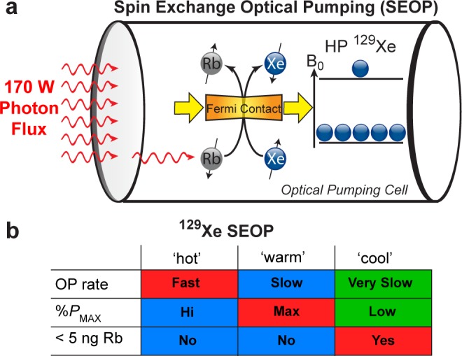
(a) Schematic of batch-mode 129Xe spin-exchange optical pumping (SEOP) using a high-power laser diode array (LDA) and 0.5 L optical pumping (OP) cell. (b) A brief qualitative summary of 129Xe SEOP parameter regions studied here Xe density and incident laser power. Note that <5 ng of residual Rb quantity in the Tedlar bag (after HP gas expansion) has been utilized in FDA-approved clinical trial protocols.
Batch SEOP of a Xe/N2 gas mixture can be canonically described by %PXe(t) = %Pmax[1 – exp(−γSEOPt)],18,21 where %Pmax is the maximum %PXe at t → ∞ and γSEOP is the exponential buildup rate constant. %Pmax and γSEOP vary with temperature, Xe/N2 polarizing mixture composition, and laser photon flux (which affects γSEOP through induced temperature changes). Following previous efforts studying batch-mode SEOP at much smaller scales and resonant laser fluxes,22−25 multiparameter (laser power, temperature, and Xe fraction) mapping14,20 of hyperpolarization conditions was recently performed in a 3D-printed clinical-scale 129Xe hyperpolarizer.15 These results demonstrated a mismatch between polarizing conditions corresponding to the maximum 129Xe polarization %Pmax and those corresponding to greatest stable γSEOP rate for a given Xe/N2 composition and laser power; the temperature condition yielding the greatest %Pmax value typically corresponded to a relatively low γSEOP value and vice versa20 (Figure 1b)—suggesting that a multitemperature approach could significantly improve the HP 129Xe production efficiency. Furthermore, both conditions (i.e., those yielding maximum %Pmax and maximum γSEOP) require that the OP-cell be cooled down to reduce Rb gas-phase concentration to an acceptable level before HP gas transfer prior to patient administration.14,19 In this work, we describe a new approach for automated batch-mode preparation of HP gases: temperature-ramped (TR) SEOP, which enables rapid PXe buildup, high maximum 129Xe polarization, and low Rb content of the final HP gas dose in one hyperpolarization procedure comprising three key steps: (i) a fast HP 129Xe buildup rate (i.e., high γSEOP) step, (ii) a high steady-state %Pmax step, and (iii) a cool-down step characterized by low γSEOP and %Pmax values but with a low residual Rb content acceptable for clinical applications. The TR-SEOP approach significantly reduces the polarization cycle time compared to conventional constant-temperature SEOP (optimized only to obtain the highest value of %Pmax), thereby markedly improving the rate of HP 129Xe production—one of the main bottlenecks for clinical translation for some applications. The added benefits of the described approach are a significantly simplified design with greater ease of automation.
Experimental Methods
129Xe Hyperpolarizer
The previously described 3D-printed 129Xe polarizer was used for the production of HP 129Xe15 following the addition of an improved gas-handling manifold: the positive-pressure gas-handling manifold is shown in detail in Figure 2. The manifold consists of several Teflon pneumatic valves (International Polymer Solutions Inc., Irvine, CA): the default position for some of these values is “open” (green valves, part no. M222OPFR-T), whereas for others the default position is “closed” (large brown valves, part no. M222CPFR-T; small brown valves, part no. S112CPFR-T). The OP-cell (Midrivers Glass Blowing, St. Charles, MO, P/N MRG350-10)15 is initially filled with unpolarized gas via a manifold of stainless steel Swagelok and VCR connections, and includes a zeolite getter to remove oxygen (Entegris Inc., Chaska, MN, part no. WGFG01KP3) and a digital pressure gauge. Flexible 1/8 in. o.d. (1/16 in. i.d.) Teflon tubing lines are used to transfer the Xe/N2 gas mixture into the OP-cell, and also comprise the in vivo “clinical path” for transferring HP gas out of the OP-cell and into various storage/transport containers including Tedlar bags. The HP gas transfer line includes a filtering element (Entegris Inc., Chaska, MN, part no. CE100 KFI4R) designed to remove residual Rb. One-way check valves (Western Analytical, Wildomar, CA, Biochek CO-5C) on the HP gas-transfer side further prevent back-flow and contamination of the OP-cell with atmospheric O2. The entire manifold can be evacuated to 7.5 × 10⁻⁵ Torr with the hyperpolarizer’s vacuum pump system (Edwards vacuum, U.K., model no. TS75W1002). However, as in many continuous-flow polarizers (e.g., refs (12, 16, and 26)), the portion of the manifold upstream of the cell is maintained at a constant (over)pressure of 2.7 atm; combined with the use of a premixed Xe/N2 gas source, this design eliminates the delay times associated with evacuation/purge cycles and gas mixing involved with cell loading. Thus, after the preparation of each HP 129Xe dose, the OP-cell is immediately reloaded with a fresh batch of Xe/N2 gas mix via the manifold. This approach also reduces concern of atmospheric O2 leaking into this portion of the manifold (or the OP-cell).
Figure 2.
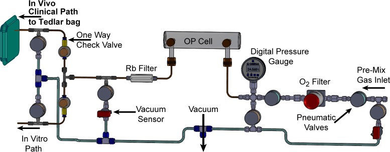
Positive-pressure gas loading manifold (nominal pressure is 2.7 atm for a 0.5 L OP-cell), which consists of Teflon pneumatic valves and tubing, one-way check valves, in-line O2 and Rb getters/filters, vacuum and pressure sensors, and two exit paths: “in vivo” (i.e., for clinical use) and “in vitro” (i.e., for experiments not involving living organisms). Implementation of the Rb filter does not appear to measurably impact 129Xe hyperpolarization (ref (20)).
OP-Cell Preparation
While the OP-cell design and procedure for preparation was described earlier,15,20 the details pertinent to the presented work are provided below.
The cell consists of a main Pyrex tubular body 9.75 in. in length with an outer diameter (o.d.) of 2.125 in. and inner diameter (i.d.) of 2 in. with the ends sealed using 2.125 in. optical flats to create an internal volume of ∼500 mL. Two threaded side stems (Chem-Glass P/N CG-350-10) used for transferring gas in and out of the OP-cell are attached orthogonal to the main body and are sealed using Teflon stopcock valves (Chem-Glass P/N CG-934-01). Each cell is pressure tested to ∼3.5 atm above atmospheric pressure before being approved for experimental operation.
Each cell is prepared by first removing the Teflon stopcock valves before being placed in KOH/methanol base-bath for a 24 h period to remove any impurities attached to the glass surface during its construction or from previous experimental use. The cell is then removed from the base bath and rinsed with distilled water, followed by methanol, and repeated at least three times. The cell is then submerged in 50/50 water–methanol solution and further ultrasonically cleaned for ∼1 h before being rinsed again with distilled water and followed with methanol before it is then placed inside a low-temperature (100 °C) oven to evaporate any residual methanol. Once the cell has dried and cooled, the next step is to coat the interior surface with siliconizing agent (Surfrasil, P/N PI-42800, Fisher Scientific), which is prepared by diluting 1 mL of Surfrasil with 9 mL of hexane. The prepared siliconizing solution is then poured into the cell via a side stem and then gently swirled for several minutes to coat all internal surfaces. The siliconizing solution is then removed and the cell is rinsed with hexane. The cell is then connected to vacuum to remove any residual hexane before it is once again placed in the low-temperature oven to be dried. This siliconized coating prevents direct contact of HP 129Xe with the glass surface and any paramagnetic centers that may exist in the glass, thus preventing 129Xe depolarization and increasing 129Xe in-cell T1 relaxation time. Achieving long in-cell 129Xe T1 times is key in building up high levels of hyperpolarization in batch-mode SEOP.
Once the OP-cell is dried and cooled, it is then ready to be loaded with ∼250 mg of molten Rb alkali metal through one of the side stems using a glass pipet to deposit a small droplet. This entire process is performed under an inert nitrogen gas atmosphere inside a glovebox to prevent oxidation of the Rb. The Teflon stopcock valves are then used to seal the OP-cell prior to its removal from the glovebox. The sealed cell is then connected to a dedicated gas-loading manifold (not of a hyperpolarizer), where it is evacuated down to <10–3 Torr and then sealed again in preparation for Rb distribution. The Rb droplet is then vaporized using a heat gun to localize heat (which is also used to heat the optical windows to prevent Rb from depositing on both optical windows of the OP-cell). While the droplet is being heated, cooled N2 gas from a pressurized liquid nitrogen Dewar is gently sprayed toward the exterior cell surface forcing condensation of Rb to form a fine layer of Rb coating down the entire length of the cell. The cell is then evacuated again to remove any nitrogen gas that had degassed from the Rb, and the process is repeated until no further degassing occurs. The well-distributed, fine Rb coating likely helps SEOP by increasing the Rb surface-to-volume ratio, allowing it to more rapidly equilibrate globally (i.e., throughout the OP-cell) with the gas-phase concentration during heating and cooling. Once the cell has been Rb-coated, the cell is then evacuated again and then loaded to ∼1240 Torr (24 psi setting of the gauge) above atmospheric pressure with the desired 129Xe/N2 gas composition and sealed.
Low-Field in Situ NMR Spectroscopy
Low-field in situ NMR spectroscopy, used to measure PXe, was performed using the radio frequency (rf) coil and the magnet setup described previously;20 the spectrometer operated at 47 kHz for both 129Xe (B0 = 4.00 mT) and proton (B0 = 1.10 mT). In situ 129Xe polarization was calculated using the 1H NMR signals from a reference sample of water protons.15,20129Xe polarization was sampled every 12 min during buildup and decay using low-tipping-angle rf excitation pulses (≪15°) emitted by a small rf coil, causing negligible detectable loss of 129Xe hyperpolarization even after the application of several (∼12–30) rf pulses.20
129Xe SEOP Hyperpolarization Conditions
All polarization experiments were conducted with a 2 in. diameter laser beam delivering 170 W of circularly polarized light (QPC Lasers) incident on the 2 in. diameter window of the OP-cell (0.5 L volume) filled with 500 Torr (67 kPa) natural abundance Xe (26.44%) and 1500 Torr (200 kPa) ultrahigh purity N2 using a 25:75 premixed Xe/N2 cylinder (Nova Gas Technologies).
Measurements of 129Xe SEOP Buildup and Decay Kinetics
SEOP buildup of 129Xe hyperpolarization was measured at four different temperatures: 42, 55, 72, and 74 °C or with a ramped temperature within this range. A simple monoexponential function was fit to each experimental time-dependent data set as follows: %PXe(t) = %Pmax[1 – exp(−γSEOPt)] + %PXe(0), where γSEOP = γSE + ΓXe = kSE[Rb] + ΓXe; γSE is the Rb/129Xe spin-exchange rate and ΓXe is the HP 129Xe spin-destruction rate (ΓXe = 1/T1),14 giving γSEOP = γSE + ΓXe = kSE[Rb] + 1/T1. 129Xe T1 was measured by monitoring the decay of HP 129Xe every 12 min at 20 °C by low-field in situ NMR in the absence of laser irradiation (see, for example, Figure 3b).
Figure 3.
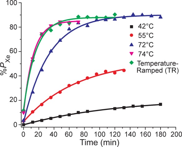
129Xe optical pumping (hyperpolarization) buildup curves for an OP-cell filled with 500 Torr 129Xe/1500 Torr N2 gas mixture under variable temperatures of 42, 55, 72, 74 °C, and TR-SEOP (74 → 72 °C).
OP-Cell Cool-Down Procedure
Typically in batch-mode optical pumping, the OP-cell must be cooled prior to HP 129Xe transfer to reduce the gas-phase Rb concentration to a level safe for administration to patients (e.g., <5 ng limits have been approved by FDA for previous 129Xe hyperpolarizers). The cryocollection of HP 129Xe utilized by most hyperpolarizers (to accumulate and concentrate HP 129Xe and remove buffer gases) also helps to remove residual Rb; however, cryocollection can also result in hyperpolarization losses and adds significantly to instrument complexity (hampering full automation). Proper cool-down of the OP-cell (while minimizing hyperpolarization losses in the gas phase) followed by rapid transfer of HP 129Xe directly into a Tedlar bag obviates the cryocollection step.14,27 Our approach14,19 uses only the aforementioned in-line Rb filter/getter to further reduce residual Rb content.
Absorption of laser emission from high-power sources can cause significant residual heating of OP-cells. The previously described OP-cell cooling procedure (here dubbed “XeNA cool-down”)14,19 utilizes a rapid and significant reduction in laser power (typically staying on or near resonance) while the OP-cell’s oven is actively cooled with the chilled (∼0 °C) output from a self-pressurized liquid N2 Dewar—resulting in only a minor loss of 129Xe hyperpolarization prior to Xe transfer.14,19 While effective, use of such Dewars for OP-cell/oven cooling is cumbersome, results in significant liquid N2 consumption over time, and would be challenging to automate. At the price of decreased cooling power (and hence speed), the current design avoids all of these problems by instead using a thermoelectric cooler15 (TEC; Kryotherm, Saint-Petersburg, Russia, P/N 380-24-AA) with recirculating air flow to regulate the OP-cell’s temperature. Correspondingly, a modified cell cooling procedure was developed (here referred to as “XeUS cool-down”—again following the name of the hyperpolarizer): After a high level of HP 129Xe is achieved (e.g., at 72 °C), the TEC switches into maximum cooling mode and the OP-cell temperature is reduced (here, either to 55 or 42 °C); cooling times for 72–55 °C and 72–42 °C transitions were ∼12 and ∼24 min, respectively (Figure 4a; precision was limited by the in situ %PXe NMR sampling rate). Decay time constants of 129Xe hyperpolarization were measured after the cell temperature was stabilized for a given condition. In two separate runs performed under identical conditions (terminating at 55 or 42 °C, respectively), the contents of the OP-cell were expanded into Tedlar bags (1 L volume, Jensen Inert Products, part no. GSTPOO1-0707S) via the gas manifold (Figure 2) for elemental analysis (by ICPMS; Element One, Inc., Wilmington, NC) to quantify residual Rb in the resulting ∼0.8 L volume of HP 129Xe gas. LDA power was maintained at 170 W at all times during OP-cell cool-down (except for 55–42 °C cool-down phase, where it was temporarily set to ∼150 W and off-resonance condition; the power reduction was achieved by decreasing the LDA current, which resulted in lower output power and LDA detuning from the resonant frequency) and refill—simplifying polarizer operation and automation.
Figure 4.
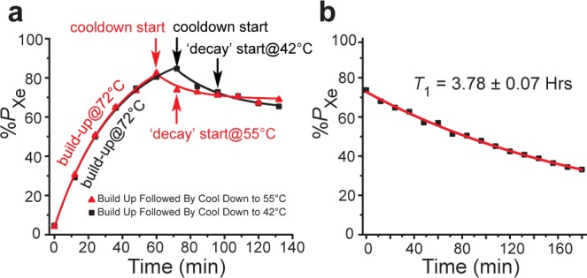
(a) Exponential fit buildup (72 °C) and decay curves of the OP cell cool down to 42 and 55 °C, respectively, of 500 Torr 129Xe. (b) T1 decay of hyperpolarized 129Xe (500 Torr partial pressure) at room temperature with the laser turned off.
Results and Discussion
Examples of buildup curves showing the 129Xe polarization dynamics obtained using either conventional (constant-temperature) SEOP or TR-SEOP are provided in Figure 3; a corresponding summary of %Pmax and γSEOP values is provided in Table 1. For the constant-temperature curves γSEOP increases steeply with temperature (as expected), owing to the growth of the γSE term because of its dependence on [Rb]—which approximately doubles with each ∼10 °C increment in this regime.28 Indeed, at 74 °C γSEOP is anomalously high: 77.8(±4.0) × 10–3 min–1 compared to 29.9(±1.2) × 10–3 min–1 at 72 °C (just 2 °C lower). This ∼2.6-fold increase indicates that [Rb] is significantly higher than what would be expected based on the externally measured OP-cell temperature,28 indicative of metastable conditions where increased laser absorption begins to result in more elevated gas temperatures and greater energy dissipation into the inner cell walls (and hence higher [Rb] in the vapor phase)—a condition dubbed “Rb prerunaway”.20 Values for %Pmax also increased with temperature but peaked at 72 °C, with %Pmax(74 °C) being lower by 5.0% ± 1.2% (Table 1). Moreover, this difference is likely to be greater under the condition of more Xe-rich batch SEOP gas mixes, where %Pmax is further away from unity. In addition to improved stability, values for %Pmax also increased in TR-SEOP versus %Pmax(74 °C), 88.0% ± 0.9% versus 85.1% ± 0.9% (Table 1). Furthermore, the ultimate goal of the SEOP procedure is to maximize %Pmax in biomedical applications, and even small gains in %Pmax are welcomed. Such behavior has been observed previously,14,15,19,20,24 and can be explained by the decrease in the spatial average of the Rb electron spin polarization, ⟨PRb⟩, resulting from greater optical density and poorer overall Rb illumination, because %Pmax = ⟨PRb⟩γSE(γSE + ΓXe)−1. Attempting SEOP at higher temperatures (even as low as 75 °C) resulted in full Rb runaway,12,25,29,30 an unstable and hysteretic condition that requires the cell to be returned to room temperature before restarting SEOP (and that must be diligently avoided—particularly when setting conditions for automation). It should also be pointed out that the Rb runaway is ultimately the result of insufficient OP-cell thermal management. Engineering solutions have been proposed recently to alleviate this problem.29 In principle, it may also be possible to improve thermal management by the addition of more thermally conductive gases like He.30,31 Thus, improved thermal management (e.g., ref (29)) could potentially allow for (stable) SEOP at even higher temperatures with higher buildup rates—to be better exploited for the early stage of the of the temperature ramp (improvements in thermal management may also allow for increases in resonant laser flux).20
Table 1. Summary of the Experimental Parameters %Pmax and γSEOP, Obtained by Data Fitting to Monoexponential Growth (%Pmax and γSEOP) during SEOP Buildupa.
| temp (°C) | %Pmax | γSEOP × 103 (min–1) | residual Rb TEC oven (ng) | residual Rb FA oven (ng)b |
|---|---|---|---|---|
| 30 | 1.19 | |||
| 40 | 4.00 ± 0.21 | |||
| 42 | 21.7 ± 1.0 | 8.0 ± 0.6 | 1.64 | |
| 55 | 53.3 ± 2.1 | 14.1 ± 1.1 | 3.4 | |
| 72 | 90.1 ± 0.8 | 29.9 ± 1.2 | ||
| 74 | 85.1 ± 0.9 | 77.8 ± 4.0 | ||
| temp-ramped (TR) | ⟨88.0 ± 0.9⟩ | ⟨62.5 ± 3.7⟩ |
Residual Rb content is reported as a function of OP-cell surface temperature based on the elemental analysis of an ∼1.0 L Tedlar bag containing ∼0.8 L of HP gas mixture after the transfer from the OP-cell through Teflon tubing with an in-line filter without cryocollection. Rb content obtained on the presented setup with a thermoelectric cooling (TEC) oven (ref (15)) utilized 1/8 in. o.d. (1/16 in. i.d.) Teflon tubing transfer lines with the temperature sensor mounted on the outer surface of the OP-cell. Residual Rb content obtained with the “open-source” hyperpolarizer with a forced air (FA) oven utilized 1/4 in. o.d. (1/8 in. i.d.) Teflon tubing transfer lines with the temperature sensor monitoring oven air temperature (refs (14 and 19)).
Ref (14).
Looking to the next phase of the HP 129Xe preparation cycle, implementation of the XEUS cool-down procedure used for the 72–55 °C transition resulted in 9.6 ± 0.5% absolute polarization loss (i.e., %PXe decrease from 82.4% to 74.5%) in ∼12 min, whereas the 72–42 °C transition resulted in 14.1 ± 0.7% absolute polarization loss (%PXe decrease from 84.6% to 72.5%) in ∼24 min. Once the OP-cell reached 55 and 42 °C, the time constants for 129Xe polarization decay were 184 ± 22 and 226 ± 12 min, respectively, further confirming that polarization losses under these conditions are relatively minor (and that [Rb] must be correspondingly low). Indeed, these decay constants are comparable to the 129Xe T1 value of 227.2 ± 4.2 min (or 3.78 ± 0.07 h) measured at 20 °C with the laser off (Figure 4b). A long cell T1 (compared to γSE–1) is highly desirable for stopped-flow HP 129Xe production because it enables PXe to approach ⟨PRb⟩. This T1 value is significantly longer than that previously reported for this polarizer (∼2.5 h for 1000 Torr Xe with 1000 Torr N2),20 and nearly twice as long than that previously reported for XeNA (T1 = 1.9 ± 0.6 h).14 This result is partially due to the lower Xe density;32 however, other contributions to achieving longer in-cell 129Xe T1 may include improvements in consistency of OP-cell preparation and lower operational temperatures that minimize wear and tear of Surfrasil OP-cell surface protection layers.
Automated gas transfer of HP 129Xe to a Tedlar bag following OP-cell cool-down to 42 °C allowed the residual Rb level to be measured—1.64 ng/0.8 L dose (Table 1). However, the time needed to reach this temperature during the cooling stage is long (∼24 min) and doing so requires the laser to be tuned (∼0.3 nm) off resonance to reduce the amount of energy absorbed by the cell. Cooling to 55 °C takes half the time and was performed without adjusting the laser from its nominal SEOP settings, providing three advantages: (i) maintaining maximum resonant photon flux helps minimize PXe losses during cooling, (ii) it removes the instrument idle time (∼10 min) that would otherwise be required to return the laser to nominal SEOP operating conditions, and (iii) it simplifies operation/automation. Importantly, the residual Rb content remained acceptable using this approach (3.4 ng/0.8 L dose). Indeed, the ratio of values for residual Rb content correlates well with the expected Rb vapor density versus temperature,28 and the values are also similar to those obtained with the previous polarizer design and cell cooling procedure (Table 1).
Given the above results separately demonstrating optimal conditions for fast PXe buildup, highest %Pmax, and low residual Rb content (Figure 1b), a combined TR-SEOP approach was investigated (Figure 3). 129Xe was first polarized for 12 min (∼1/γSEOP) at the highest allowed temperature (74 °C, the highest temperature that was sufficiently stable for automation over short periods), after which the temperature was ramped down to the value at which the highest 129Xe polarization was achieved (72 °C, reached in ∼9 min). Despite the temperature change, the time course data could still be reproduced by a simple exponential—giving an effective “average” buildup rate ⟨γSEOP⟩ = (62.5 ± 3.7) × 10–3 min–1 and corresponding effective maximum PXe value of ⟨%Pmax⟩ = 88.0 ± 0.9% (Table 1). Importantly, this effective buildup rate was near the peak value achieved at 74 °C [(77.8 ± 4.0) × 10–3 min–1], and over twice that obtained at 72 °C [(29.9 ± 1.2) × 10–3 min–1]. Moreover, the corresponding effective ⟨%Pmax⟩ value for the TR-SEOP experiment very nearly matched the peak value achieved at 72 °C (90.1 ± 0.8%). While the %Pmax gain over constant-temperature SEOP value obtained at 74 °C (85.1 ± 0.9%) was modest, this is in part because 129Xe polarization levels are already near unity. Larger relative gains are expected for greater Xe densities where 129Xe polarization levels tend to be lower,14,20,32 with a greater disparity between values obtained at higher temperatures (with greater γSEOP) and those obtained at lower temperatures (with higher %Pmax values but much longer buildup times)—and where the risks of unstable SEOP and Rb runaway are greater (because of faster Rb electronic spin-destruction rates,33,34 greater laser absorption and hence energy deposition within the cell,30 and lower gas thermal conductivity31). Indeed, these differences are likely to be even more pronounced with the development of better thermal management approaches29 to allow higher temperatures at the beginning of the TR-SEOP process, providing a route to further gains in accelerating the HP 129Xe production cycle.
We note that the actual cool-down times were less than 12 and 24 min for 72–55 °C and 72–42 °C transitions, respectively. Moreover, better thermal management, i.e., engineering solutions allowing for faster OP-cell cool-down and heating, can further reduce the cool-down time, and relatively small polarization losses during cool-down demonstrated here can be further minimized. Furthermore, reducing cool-down time will also positively decrease the HP 129Xe production cycle time, and increase the effective HP 129Xe production rate (L/h).
The presented batch-mode TR-SEOP method operated in three temperature regimes, and the method can be potentially further improved by circumventing experimental hardware limitations (e.g., a more powerful TEC module to enable faster temperature change, particularly important during the cool-down phase) as well as by implementing more advanced temperature ramping during SEOP. For example, as pointed out by an anonymous reviewer, one way to consider the general approach is to maximize d%P/dt by derivation and implementation of a temperature variation function comprising optimal temperature choices for each moment over the course of the SEOP run for a given set of conditions—which can be enabled by careful %Pmax mapping of SEOP parameters20 as well as characterization and improvement of the polarizer components used to heat and cool the cell. In any case, detailed modeling and experimental implementation of such optimization of the time-dependent SEOP is the subject of ongoing work.
While the fractional concentration of hyperpolarized xenon was relatively low, i.e., ∼200 mL in ∼800 mL of ejected hyperpolarized Xe/N2 gas mixture, the apparent 129Xe polarization %Papp27 (typically defined as noble gas polarization multiplied by its fractional concentration) was still sufficiently high, i.e., %Papp ∼ 19%, after gas transfer from the OP-cell into a Tedlar bag. Such levels of %Papp of ∼0.8–1 L hyperpolarized gas mixtures using 129Xe have been shown sufficient for 3D human lung imaging.14,35,36
Conclusions
Taken together, the above improvements in operation and design can provide significant increases in production capacity for stop-flow SEOP hyperpolarizers, without sacrificing the high level of nuclear spin polarization achieved. First, the TR-SEOP approach provided near-unity (88.0 ± 0.9%) %PXe at 500 Torr Xe in 0.5 L clinical-scale OP-cell under conditions of stable automation—corresponding to NMR/MRI enhancements of ∼3.1 × 10⁵ and ∼2.3 × 10⁸ at 3 T and 4 mT, respectively (fields relevant to clinical imaging and current in situ detection)—with over twice the buildup rate of the corresponding constant-temperature operation. Next, the features provided by the positive-pressure manifold and the cell cooling approach help to minimize the instrument idling time by cutting the delay required for cell cooling in half (for the current TEC-cooled design) and eliminating the delays otherwise required for gas-line evacuation/purge cycles, gas mixing, and returning the laser to nominal SEOP operation. Indeed, these improvements contribute to a shortened and greatly simplified polarization cycle (comprising only four steps, Figure 5) that lends itself well to automated, looped operation for continuous production of batches of HP 129Xe for a wide range of preclinical and clinical applications. Using 2/⟨γSEOP⟩ as the effective pumping time20 and ∼15 min as the overall cooling/idle time, the current hyperpolarizer in TR-SEOP mode produces >1 L/h with near-unity 129Xe polarization using the current 25:75 Xe/N2 gas mixture (with %Papp ∼ 19%)—with residual Rb remaining within acceptable limits for clinical use (<5 ng/0.8 L dose). Although the absence of cryocollection leads to 4-fold dilution of the HP 129Xe, corresponding speed gains in HP 129Xe production are also expected with richer Xe mixtures—the subject of future efforts. Finally, while the present work concerns only HP 129Xe, these results should also be readily applicable to improved production of HP quadrupolar noble gas isotopes (83Kr and 131Xe).37−39
Figure 5.

Operational diagrams of clinical-scale batch-mode SEOP polarizers: conventional (top) and enabled by the new temperature-ramped (TR) SEOP method presented here (bottom).
Acknowledgments
We thank the anonymous reviewers for helpful suggestions. Work at Vanderbilt and SIUC is supported by a DoD CDMRP Era of Hope Award W81XWH-12-1-0159/BC112431. Portions of this work were supported by SIU Office of Sponsored Projects Administration (OSPA). B.M.G. is supported in part by the NIH (2R15EB007074-02). E.Y.C. is supported in part by the NIH (3R00CA134749-03). M.J.B. acknowledges the support of the School of Medicine, University of Nottingham, U.K. M.S.R. acknowledges the support of Department of Defense, Defense Medical Research and Development Program, Applied Research and Advanced Technology Development Award: Grant No. W81XWH-11-2-0076 (DM09094).
The authors declare no competing financial interest.
Funding Statement
National Institutes of Health, United States
References
- Kurhanewicz J.; Vigneron D. B.; Brindle K.; Chekmenev E. Y.; Comment A.; Cunningham C. H.; DeBerardinis R. J.; Green G. G.; Leach M. O.; Rajan S. S.; Rizi R. R.; Ross B. D.; Warren W. S.; Malloy C. R. Neoplasia 2011, 13, 81–97. [DOI] [PMC free article] [PubMed] [Google Scholar]
- Goodson B. M. J. Magn. Reson. 2002, 155, 157–216. [DOI] [PubMed] [Google Scholar]
- Ruset I. C.; Tsai L. L.; Mair R. W.; Patz S.; Hrovat M. I.; Rosen M. S.; Muradian I.; Ng J.; Topulos G. P.; Butler J. P.; Walsworth R. L.; Hersman F. W. Concepts Magn. Reson., Part B 2006, 29B, 210–221. [DOI] [PMC free article] [PubMed] [Google Scholar]
- Tsai L. L.; Mair R. W.; Rosen M. S.; Patz S.; Walsworth R. L. J. Magn. Reson. 2008, 193, 274–285. [DOI] [PMC free article] [PubMed] [Google Scholar]
- Branca R. T.; Cleveland Z. I.; Fubara B.; Kumar C. S. S. R.; Maronpot R. R.; Leuschner C.; Warren W. S.; Driehuys B. Proc. Natl. Acad. Sci. U.S.A. 2010, 10783693–3697. [DOI] [PMC free article] [PubMed] [Google Scholar]
- Dregely I.; Mugler J. P.; Ruset I. C.; Altes T. A.; Mata J. F.; Miller G. W.; Ketel J.; Ketel S.; Distelbrink J.; Hersman F. W.; Ruppert K. J. Magn. Reson. Imaging 2011, 33, 1052–1062. [DOI] [PMC free article] [PubMed] [Google Scholar]
- Acosta R. H.; Blümler P.; Münnemann K.; Spiess H.-W. Prog. Nucl. Magn. Reson. Spectrosc. 2012, 66, 40–69. [DOI] [PubMed] [Google Scholar]
- Mugler J. P.; Altes T. A. J. Magn. Reson. Imaging 2013, 37, 313–331. [DOI] [PMC free article] [PubMed] [Google Scholar]
- Norquay G.; Parnell S. R.; Xu X.; Parra-Robles J.; Wild J. M. J. Appl. Phys. 2013, 113, 044908. [Google Scholar]
- Wild J.; Marshall H.; Xu X.; Norquay G.; Parnell S.; Clemence M.; Griffiths P.; Parra-Robles J. Radiology 2013, 267, 251–255. [DOI] [PubMed] [Google Scholar]
- Leawoods J. C.; Yablonskiy D. A.; Saam B.; Gierada D. S.; Conradi M. S. Concepts Magn. Reson. 2001, 13, 277–293. [Google Scholar]
- Zook A. L.; Adhyaru B. B.; Bowers C. R. J. Magn. Reson. 2002, 159, 175–182. [DOI] [PubMed] [Google Scholar]
- Ruset I. C.; Ketel S.; Hersman F. W. Phys. Rev. Lett. 2006, 96, 053002. [DOI] [PubMed] [Google Scholar]
- Nikolaou P.; Coffey A. M.; Walkup L. L.; Gust B. M.; Whiting N.; Newton H.; Barcus S.; Muradyan I.; Dabaghyan M.; Moroz G. D.; Rosen M.; Patz S.; Barlow M. J.; Chekmenev E. Y.; Goodson B. M. Proc. Natl. Acad. Sci. U.S.A. 2013, 110, 14150–14155. [DOI] [PMC free article] [PubMed] [Google Scholar]
- Nikolaou P.; Coffey A. M.; Walkup L. L.; Gust B.; LaPierre C.; Koehnemann E.; Barlow M. J.; Rosen M. S.; Goodson B. M.; Chekmenev E. Y. J. Am. Chem. Soc. 2014, 136, 1636–1642. [DOI] [PMC free article] [PubMed] [Google Scholar]
- Driehuys B.; Cates G. D.; Miron E.; Sauer K.; Walter D. K.; Happer W. Appl. Phys. Lett. 1996, 69, 1668–1670. [Google Scholar]
- Schrank G.; Ma Z.; Schoeck A.; Saam B. Phys. Rev. A 2009, 806063424. [Google Scholar]
- Walker T. G.; Happer W. Rev. Mod. Phys. 1997, 69, 629–642. [Google Scholar]
- Nikolaou P.; Coffey A. M.; Walkup L. L.; Gust B. M.; Whiting N. R.; Newton H.; Muradyan I.; Dabaghyan M.; Ranta K.; Moroz G.; Patz S.; Rosen M. S.; Barlow M. J.; Chekmenev E. Y.; Goodson B. M. Magn. Reson. Imaging 2014, 32, 541–550. [DOI] [PMC free article] [PubMed] [Google Scholar]
- Nikolaou P.; Coffey A. M.; Ranta K.; Walkup L. L.; Gust B.; Barlow M. J.; Rosen M. S.; Goodson B. M.; Chekmenev E. Y. J. Phys. Chem. B 2014, 118, 4809–4816. [DOI] [PMC free article] [PubMed] [Google Scholar]
- Walker T. G. J. Phys.: Conf. Ser. 2011, 294, 012001. [Google Scholar]
- Rosen M. S.; Chupp T. E.; Coulter K. P.; Welsh R. C.; Swanson S. D. Rev. Sci. Instrum. 1999, 70, 1546–1552. [Google Scholar]
- Nikolaou P.; Whiting N.; Eschmann N. A.; Chaffee K. E.; Goodson B. M.; Barlow M. J. Magn. Reson. 2009, 197, 249–254. [DOI] [PubMed] [Google Scholar]
- Whiting N.; Nikolaou P.; Eschmann N. A.; Barlow M. J.; Goodson B. M. J. Magn. Reson. 2011, 208, 298–304. [DOI] [PubMed] [Google Scholar]
- Whiting N.; Nikolaou P.; Eschmann N. A.; Goodson B. M.; Barlow M. J.; Lammert R.; Ungar J.; Vaissie L. Appl. Phys. B: Lasers Opt. 2012, 106, 775–788. [Google Scholar]
- Mortuza M. G.; Anala S.; Pavlovskaya G. E.; Dieken T. J.; Meersmann T. J. Chem. Phys. 2003, 118, 1581–1584. [Google Scholar]
- Hughes-Riley T.; Six J. S.; Lilburn D. M. L.; Stupic K. F.; Dorkes A. C.; Shaw D. E.; Pavlovskaya G. E.; Meersmann T. J. Magn. Reson. 2013, 237, 23–33. [DOI] [PMC free article] [PubMed] [Google Scholar]
- Alcock C. B.; Itkin V. P.; Horrigan M. K. Can. Metall. Q. 1984, 23, 309–313. [Google Scholar]
- Witte C.; Kunth M.; Rossella F.; Schröder L. J. Chem. Phys. 2014, 140, 084203. [DOI] [PubMed] [Google Scholar]
- Whiting N.; Newton H.; Morris P.; Barlow M. J.; Goodson B.. Phys. Rev. A, submitted for publication. [Google Scholar]
- Kaye G. W. C.; Laby T. H.. Tables of Physical and Chemical Constants; Longman: Essex, U.K., 1995; Vol. 16. [Google Scholar]
- Anger B. C.; Schrank G.; Schoeck A.; Butler K. A.; Solum M. S.; Pugmire R. J.; Saam B. Phys. Rev. A 2008, 78, 043406. [Google Scholar]
- Bouchiat M. A.; Brossel J.; Pottier L. C. J. Chem. Phys. 1972, 56, 3703–3714. [Google Scholar]
- Nelson I. A.; Walker T. G. Phys. Rev. A 2002, 65, 012712. [DOI] [PubMed] [Google Scholar]
- Kaushik S. S.; Cleveland Z. I.; Cofer G. P.; Metz G.; Beaver D.; Nouls J.; Kraft M.; Auffermann W.; Wolber J.; McAdams H. P.; Driehuys B. Magn. Reson. Med. 2011, 65, 1155–1165. [DOI] [PMC free article] [PubMed] [Google Scholar]
- Driehuys B.; Martinez-Jimenez S.; Cleveland Z. I.; Metz G. M.; Beaver D. M.; Nouls J. C.; Kaushik S. S.; Firszt R.; Willis C.; Kelly K. T.; Wolber J.; Kraft M.; McAdams H. P. Radiology 2012, 262, 279–289. [DOI] [PMC free article] [PubMed] [Google Scholar]
- Lilburn D.; Pavlovskaya G. E.; Meersmann T. J. Magn. Reson. 2012, 229, 173–186. [DOI] [PMC free article] [PubMed] [Google Scholar]
- Stupic K. F.; Cleveland Z. I.; Pavlovskaya G. E.; Meersmann T. J. Magn. Reson. 2011, 208, 58–69. [DOI] [PMC free article] [PubMed] [Google Scholar]
- Pavlovskaya G. E.; Cleveland Z. I.; Stupic K. F.; Basaraba R. J.; Meersmann T. Proc. Natl. Acad. Sci. U.S.A. 2005, 102, 18275–18279. [DOI] [PMC free article] [PubMed] [Google Scholar]