Abstract
Bistable microvalves are of particular interest because of their distinct nature requiring energy consumption only during the transition between the open and closed states. This characteristic can be highly advantageous in reducing the number of external inputs and the complexity of control circuitries for microfluidic devices as contemporary lab-on-a-chip platforms are transferring from research settings to low-resource environments with high integratability and small form factor. In this paper, we first present manually operatable, on-chip bistable pneumatic microstructures (BPM) for microfluidic manipulation. The structural design and operation of the BPM devices can be readily integrated into any pneumatically powered microfluidic network consisting of pneumatic and fluidic channels. It is mainly comprised of a vacuum activation chamber (VAC) and a pressure release chamber (PRC), which users have direct control through finger pressing to switch between bistable vacuum state (VS) or atmospheric state (AS). We have integrated multiple BPM devices into a 4-to-1 microfluidic multiplexor to demonstrate on-chip digital flow switching from different sources. Furthermore, we have shown its clinical relevance in a point-of-care diagnostic chip that process blood samples to identify the distinct blood types (A/B/O) on chip.
Introduction
Introduction of lab-on-a-chip devices has revolutionized the way contemporary science has been conducted by providing investigative methodologies that minimize target sample size, high-resolution detection and sensitivity, rapid analytic processing, and most importantly, precise flow control and manipulation at micro-nanoscales.1 Recent demands for translational applications have been driving the continual development of microfluidic innovations from the laboratories to the clinic applications and the field uses.2 In principle, the fundamental building blocks of a microfluidic device consist of micropumps to drive the miniature fluidic flow and microvalves to regulate the flow direction.3 Microvalves can be further categorized into active and passive devices, depending on whether an external power is required; and subcategorized by its governing operation principle, which can have reliance on electromagnetic, thermopneumatic, electrostatic, phase change, or capillary effects.4, 5
Among the large number of microvalve designs proposed over the past decade, bistable microvalves represent a group of mechanical valves of particular interest due to their uniqueness of remaining structurally stable (i.e., no energy consumption) in either open or closed states and requiring power input only to transition between the two states. This could be of significant use in low-resource settings or field applications. In a classic bistable design, there exists a moving element of microvalves that experiences mechanical stress during the passing or blocking of incoming liquid flow. Switching between the bistable states in the microvalves has often been achieved through principles involving a combination of electrostatic, electromagnetic, thermoelectric, and pneumatic actuations. One of the earlier bistable microvalve designs employs two pneumatically coupled membranes sharing the same air volume to cyclically deflect and seal the nozzle, with each responding to the electrostatic pulling force generated by a pair of electrodes underneath to switch the ON/OFF position.6 Electromagnetism has also been utilized by others as the driving force to switch valves between the ON/OFF states7-9 and several of them have also utilized external sources of magnet forces to maintain the deflected states.9-12 Another widely adopted actuation strategy is to implement electrothermal expansion via micropatterned heaters, also known as thermopneumatic designs, as the on-demand volume control of a working fluid to displace the microvalve membrane.12-17 More recently, phase-changing materials have been reported to be a viable option, serving as the structural material in the valve actuation. In one implementation, a solid paraffin block is melted by an electrical heater to permit flow.18, 19 Alternatively, another effort includes a liquid metal material (known as Field's metal, i.e., 32.5% Bi, 51% In, and 16.5% Sn) to hold the membrane position at two different states.20 Although bistable switching has been successfully achieved in the above designs, all of them require dedicated microelectrode designs and corresponding electrical connections to be fabricated as well as complex external driving circuitries to be programmed. The screw valve in PDMS is a straightforward concept, allowing reversible structural changes to define the open and close states of the PDMS valve.21 However, it requires additional operational steps each time and non-monolithic structures to embed threading structures for screw insertion, and introduces direct metal-elastomer contact, which can pose reliability concerns of the device during the initial implementation and over repetitive usage. Tremendous efforts utilizing normally-open or closed microfluidic microvalves have been previously reported and fully investigated by other groups.22-28
Recently, the emerging trend has been focused on technology transfer, the process of taking science and engineering from laboratory research settings to less equipped environments such as patient's homes, rural areas, and even third world countries. For new technologies to be more readily accessible to the general public, the device needs to conform to the concept of simplicity. Whitesides' group has pioneered the platform of paper-based microfluidics, transferring technologies into applications requiring minimal prerequisites for broader impact.29 The push-button valve utilized in the paper-based microfluidics brings another intriguing idea, where an air gap acts as a valve chamber separating flow between multilayer channels and a manual squeeze connects the layers to permit flow.30 It is simple but irreversible since the connection of multilayer channels cannot be reset in the midst of flow. However, certain processes prefer traditional laminar flow in geometrically confined microfluidic channels. As such, one approach to simplifying microfluidic analysis systems is to reduce the number of external inputs/connections by integrating parts of the chip control onto the device itself. A liquid-handling chip with functionalities of metering, mixing, incubation, and wash has been reported to include only four state-selection vacuum inputs and one constant vacuum power source.31 More recently, the integrated pneumatic oscillators have been shown to function as timing clock circuits to deliver microflow on chip without complex electronics.32 The SlipChip is another device platform that performs microfluidic multiplexing reactions by simply sliding two plates of reagent-containing wells array over each other for high throughput biochemical analysis, which is highly suitable for low-resource settings.33-35 Another group reported an on-chip controlled “squeeze-chip” pump realized by cascading two one-way check valves, thus excluding additional pumping instruments in their biochemical assays.36 In such miniature and portable devices, bistable microvalves can further eliminate operational complications and provide new multifunctionalities in the bioassay. Rhee et al. described the development of microfluidic analogs to logic circuits based on vacuum pneumatics and presented an example of a multiplexor regulated through bistable flipflops, which functioned in the presence of continuous vacuum supply generation.37
In this paper, we first present a manually operatable on-chip bistable microdevice enabled by vacuum pneumatics, referred to as bistable pneumatic microstructure (BPM), for on-demand fluid flow manipulation without the presence of any internal microelectrodes or external controlling circuitries. The simple design and operation of the BPM device make it readily incorporated into any standard pneumatically powered microfluidic network,23, 38, 39 which basically consists of moving diaphragm membranes sandwiched between two microfluidic layers patterned with fluidic and pneumatic channels and chambers. Neither electrodes nor metal depositions are necessary in the valve control; therefore, no additional fabrication complexity is introduced to the manufacturing process. Instead, a 3D vacuum pneumatic network has been utilized to maintain the bistable states, whereas the transition between the ON/OFF states is triggered directly by a simple manual operation (i.e., “finger pressing'). This grants end users a simple and instantaneous control over the operations of the device without constantly updating any control program, making it particularly useful in any biological laboratory or low-resource setting. Importantly, it requires only a single vacuum source to hold the states of multiple BPM devices in parallel; in such a case, either a portable micro vacuum pump or a manually operatable vacuum source can make a network of the pneumatically powered switches functional. The integrated bistable microvalve with simple actuation mechanism allows further miniaturization of the devices, reduction in the manufacturing cost, improvement of the portability, and maintain a high degree of fluidic control and multiplexibility, which are of increasing importance to biological analyses and point-of-care applications. The utilities of BPM to microfluidic operations have been demonstrated in a 4-to-1 microfluidic multiplexor where the supply of fluids from 4 different inlets can be determined simply by operating the BPM-enabled microvalves in the fluidic channels. Clinical relevance of BPM has been further exemplified in a point-of-care blood-typing diagnostic chip. In the POC device, the flows of blood samples and antibody serums are individually controlled by two sets of BPM-enabled microvalves, from which blood-typing can be processed in two separate micro-reactors to identify individual blood (A/B/O) types.
Experimental
Device fabrication
The bistable microstructure devices were microfabricated using three layers of laser-machined polydimethylsiloxane (PDMS) (Sylgard 184, Dow Corning), in which the middle layer of a thin membrane (200 μm in thickness) was oxygen plasma-bonded between the other two thicker PDMS slabs (of 1.0-1.5 mm in thickness) that had microstructures etched into them via a CO2 laser engraver (VersaLaser, Universal Laser System).40-44 PDMS was prepared at a mixing ratio of 10:1 base to curing agent. Figure 1 shows the microvalve structures in each layer prior to the assembly and bonding. Although laser microfabrication was utilized in our study for the rapid prototyping purpose, conventional template molding or soft lithography could also be a substitute.45 Fabrication of the middle membrane layer, however, was most convenient through the laser-etching technique as it could directly etch through the membrane with various heights and create microstructures to serve as suspended cantilevers within the bistable microvalve design. The top layer of 1.0 mm in thickness had been engraved with deep recess chambers of 2.0 mm in width and 900 μm in depth while leaving the center with a rectangular pillar structure. See ESI and Fig. S1 for more detailed information regarding structure dimensions. Finally, the three PDMS layers were stacked, aligned and bonded under a microscope manually. The BPM concept and its integration with the microfluidic devices became functional when a micro vacuum pump or a manually operatable vacuum source was connected to the designated vacuum port.
Fig. 1.
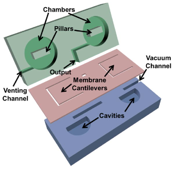
Structure and assembly of a manually controllable bistable pneumatic microstructure (BPM) for on-chip fluidic manipulation.
Vacuum sources
Three different sources of vacuum were utilized to make the bistable microstructures operational. As reliable but least portable source, the in-house facility vacuum line was used to provide a constant suction pressure around 85 kPa. For higher portability, a micro vacuum pump (KPV-20A6V, Clark Solutions) was used as the source to provide a consistent suction pressure of 30 kPa. For most simplicity, vacuum pressure syringe (VacLok C1075, Qosina) offered the needed negative suction pressure of 94 kPa, but might require reactivation after repetitive or extended use. One can simply pull and lock the syringe to establish negative pressure at the very beginning, and no further energy was required during the performance period.
Preparation of blood-typing Assay
Monoclonal anti-Blood Group A and anti-Blood Group B (SAB4700677 and SAB4700676), purchased from Sigma Aldrich, were loaded into the device at 3 μl volume. Healthy whole blood was diluted with Dulbecco's Phosphate Buffered Saline (DPBS, D8537, Sigma Aldrich) in a 1:4 ratio prior to being loaded into the device. Once the channel was filled with the blood sample, the blood along with the antibody A/B serum entered and mixed at their respective assay detection chambers for agglutination to occur.
Results and discussion
Structural design of BPM
Figure 1 illustrates the layer-by-layer structure and assembly of the bistable pneumatic microstructure (BPM). As can be seen, the BPM device is comprised of a top layer with two manually pressable chambers, one for vacuum activation and the other for pressure release. Each chamber has a central pillar resting on a deformable membrane in the middle layer; and a bottom layer hosting semicircular cavities that allow the middle membrane to deform when pushed by the pillar structure. The deformable membrane also serves as a pneumatic check-valve that separates the chamber and the inlet channel in the bottom layer. In addition, a vacuum channel connects to an external vacuum source, a venting channel to the atmospheric environment, and interconnecting channels running through the layers to connect the two chambers. Furthermore, there is an output port branching from the interconnecting channels in-between the chambers to provide either vacuum or atmosphere pressure to the microfluidic networks to be controlled.
Operational principle of BPM
Figure 2 shows the operational principle of the BPM device. As previously mentioned, the two chambers can be deformed individually to activate or release the vacuum state (VS). The chamber adjacent to the vacuum channel, referred to as the vacuum activation chamber (VAC), when pressed, connects to the vacuum channel by stretching the deformable membrane, as shown in Fig. 2b. The VS would remain even after the compression force has been released, as a differential pressure between the ambient and the VAC chamber keeps the chamber and the membrane deflected in Fig. 2c. Alternatively, the pressure release chamber (PRC) can be manually activated to direct the internal pressure to the ambient by pressing the corresponding membrane check-valve, which consecutively removes the pressure gradient in the VAC chamber and closes its connection to the vacuum channel. Eventually, it brings the BPM back to its original AS state, as shown in Fig. 2d. In brief, when the VAC chamber is pressed, the VS would be activated and self-sustained. To release back to the atmospheric state (AS) by pushing the PRC chamber, it would equalize the internal and external pressures and reset the BPM device. The key of the BPM device is that mechanical energy is only required during the transitions between the vacuum and atmospheric states.
Fig. 2.
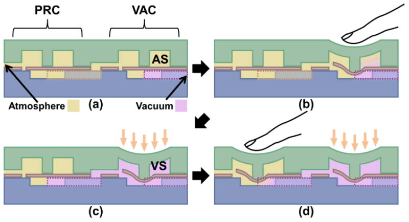
Illustration of the operational principle of the BPM devices. (a) In the original atmospheric state (AS), both vacuum activation chamber (VAC) and pressure release chamber (PRC) are relaxed. (b) Manual pressing of VAC opens the vacuum channel. (c) Vacuum fills the chamber and maintains the bistable vacuum state (VS). (d) Manual pressing of PRC releases the vacuum in VAC back to atmospheric pressure and cycles back to (a).
Figure 3 shows a functional BPM device directing the output port to a pneumatically operated normally-closed microvalve. Demonstrating its operation, Fig. 3b-g show a colored fluid is injected into the microfluidic channel while a vacuum source is applied to the BPM network. It starts with the AS of the BPM device, leaving the microfluidic microvalve closed (Fig. 3b). In Fig. 3c, the VAC chamber is manually compressed by a tweezer. The vacuum immediately perfuses through the VAC chamber and the output port, opening the microvalve for flow. As can be seen in Fig. 3d, the opened microvalve chamber is filled with the colored fluid after the VS takes place. Fig. 3e shows the self-sustained VS of the bistable microfluidic device, as previously described, no mechanical energy is required to hold the state, since a differential pressure is built across the VAC chamber. To release the VS back to the AS, the PRC chamber is squeezed by the tweezer in Fig 3f. Subsequently, the forced connection between the PRC and VAC chambers vents the VAC chamber and blocks the vacuum channel by returning the check-valve membrane to its original AS position. At this point, both the BPM device and output port are reset to the AS, and the microfluidic microvalve stops the flow where the colored fluid is depleted from the microvalve chamber in Fig. 3g. This completes the entire cycle of the bistable operations of the BPM device, which also has been tested to withstand at least 200 cycles of VS/AS without showing any degradation of performance and structural integrity when using the in-house facility vacuum line as the vacuum source (See ESI Fig. S2).
Fig. 3.
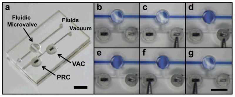
(a) A BPM device outputting to a normally-closed microvalve in a straight microfluidic channel. (b-g) BPM operations supplying output port with pneumatic vacuum for opening or closing of the normally-closed microvalve in fluid flow regulation. (b) Initially, the normally-closed microvalve remains closed and VAC is in the atmospheric state. (c) VAC is being manually pressed. (d) Once pressed, the normally-closed microvalve opens. (e) The microvalve stays open after the manual pressure is removed as VAC keeps under the vacuum state. (f) PRC is being manually pressed. (g) Once pressed, the normally-closed microvalve closes and returns to the initial state (b). (scale bars: 3 mm)
Characterizations of BPM
Figure 4 shows the minimum vacuum pressure (left axis and blue line) required to open the normally-closed valve under the given fluidic pressures (2.5, 5.0, 7.5, and 10.0 kPa) and the minimum valve-activation force (ΔF, right axis and red line) is calculated based on the pressure (P) and acting surface area (A) as shown in equation 1:
Fig. 4.
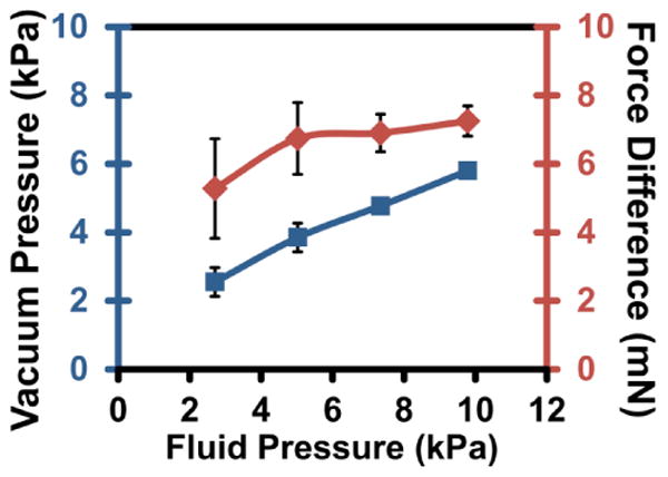
Characterizations of the BPM device. Minimum vacuum pressure (blue line) required to open a valve under fluidic pressures and the minimum valve-activation force (red line) at these respective pressures.
| (1) |
As can be seen, the valve-activation force remains relatively constant at 7 mN in the fluidic pressure range from 5-10 kPa, which represents the minimum force to overcome the physical interaction (e.g., membrane deflection and surface adhesion) and open the valve. At the lower fluidic pressure (<5 kPa), a weaker vacuum level does not open the valve completely and immediately, instead fluidic pressure is gradually released and more difficult to pinpoint the exact threshold value. Therefore, it is advised to operate the BPM device with a vacuum supply pressure of ≥5 kPa. The experimental setup of the pressure characterization is illustrated in ESI Fig. S3. The experimental setup is constructed similarly to previous works by constantly monitoring vacuum supply and fluidic outlet channel pressures.23 Furthermore, pressure characterization of a BPM connected to a vacuum syringe is shown in ESI Fig. S4. Each toggle of BPM using the vacuum syringe as the vacuum source results in an average loss of 0.198 ± 0.078 kPa (n=109). As seen in ESI Fig. S4, after more than 100 switching operations (potentially >400 cycles between 94 kPa and 5 kPa), the manual vacuum can still perform as an adequate vacuum source, which proves its potential application in low and limited resource settings without needing any external powering. Also shown in ESI Fig. S4 is the constant leakage of vacuum through the PDMS microfluidic network. The vacuum syringe itself slowly loses pressure at an approximate rate of 0.0040 kPa/s and when connected to BPM devices at a rate of 0.0133 kPa/s. Based on these measurements, a BPM device with vacuum syringe source is expected to last around 2 hours with the initial vacuum level at 94 kPa and lowest controllable vacuum level at 5 kPa. An optional visual cue to indicate vacuum supply pressure is shown in ESI Fig S5.
BPM-controlled microfluidic multiplexor
The BPM device can be extended to a 4-to-1 microfluidic multiplexor as it provides on-demand microfluidic directional control. As shown in Figure 5, the multiplexing device consists of 4 parallel converging microfluidic channels and a two-stage microvalve gate controlled by 4 BPM devices. Red and blue colored solutions (5 μl) are loaded to individual channel inlets in an alternating fashion. In Fig. 5b, the two top BPMs are first switched to VS to open the top channel and allow flow of red-dyed solution. The activation of the two top BPMs corresponds to the binary code “11” as shown in Fig. 5g. In the next step, to open the second channel and deliver the blue-dyed solution, the top left and bottom right BPMs are switched to VS and are represented by the “10” address code (in Fig. 5c and 5h). Subsequently, the third and fourth channels are opened to allow liquid flows; they correspond to the binary address codes of “01” (in Fig. 5d and 5i) and “00” (in Fig. 5e and 5j), respectively. In summary, our 4-to-1 multiplexor adapts a 2-bit binary address code to represent flow access from 4 different reservoir sources. The control configuration can be expanded to a larger system housing more input channels. For instance, a 3-bit system allows for 8(=23) microfluidic channels to be completely regulated by 6(=2×3) BPMs and a 4-bit system allows for 16(=24) microfluidic channels to be completely regulated by 8(=2×4) BPMs.37, 46, 47 The governing formula in an n-bit system can be expressed as a multiplexor with 2n channel inputs requiring 2n BPMs to control.
Fig. 5.
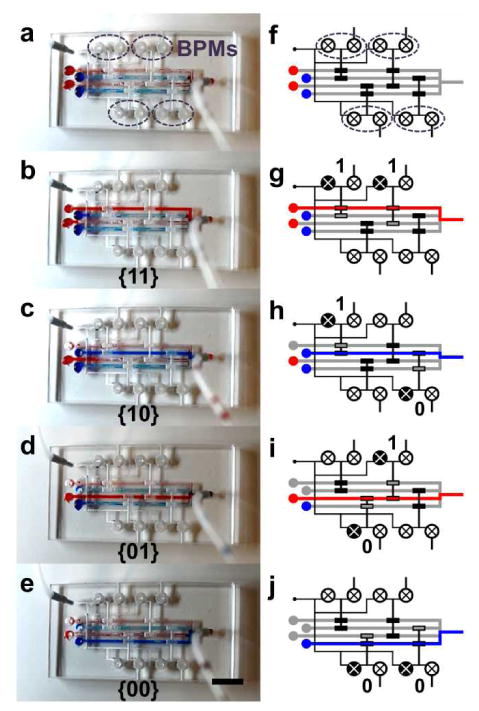
(a) A 4-to-1 microfluidic multiplexor chip with 4 BPM devices. (b-e) Flow source is switched from different reservoirs. (f-j) Illustrations depicting the BPMs involved in the flow switching and the corresponding address codes. (scale bar: 5 mm)
Furthermore, the BPM-controlled multiplexor can be utilized to devise a microtube-based immunoassay for point-of-care diagnosis of HIV in a low-resource setting, similar to previous reports.48, 49 As shown in Fig. S6, the multiplexer contains four BPM-controlled inlets loaded with blood sample (B), wash buffer (W), gold-labeled goat antibody (G) and silver nitrate reducing solution (S), respectively, in addition to a constant air supply channel. In particular, sample analytes containing HIV-specific antibodies are captured at the detection zone with wash buffer following to remove excess materials. Gold-labeled goat antibodies are used to label captured analytes, while silver nitrate with reducing solution permits visual indication. The segmented flow for immunoreaction can be achieved by consecutively opening and closing the BPM controller at each inlet, in the order of B/W/G/W/S, with air segments between each solution preventing undesired diffusion and reaction. These sequential segments are then introduced through the detection zone to perform biomolecular analysis. Therefore, it is imperative to implement such an on-chip manual BPM control to flow samples and reagents in a controlled and sequential fashion in a low-resource environment.
BPM-controlled blood-typing device
Figure 6 illustrates a point-of-care blood-typing device for A/B/O-type blood, which incorporates two BPM devices to direct a minute amount of blood sample (5-10 μl) to different immunoassay sites. Using the same fabrication procedure previously described, the blood-typing device consists of a horizontal loading channel and two vertical intersecting channels to introduce the samples into two assaying chambers containing monoclonal anti-blood groups A and B, where the agglutination of antibodies with the corresponding antigens would take place, as shown in Fig. 6a and 6d. In particular, there are seven normally-closed microvalves controlled by two BPM regulators to direct liquid flow through the device, three along the horizontal channel and two along each vertical channel. Specifically, the three horizontal microvalves are simultaneously regulated by a BPM device for loading the blood sample. Once the loading BPM regulator is switched to the vacuum state, the blood sample is drawn into the device through the horizontal channels as seen in Fig. 6b and 6e. Afterwards, the loading BPM device is switched OFF to the atmospheric pressure, while the assaying BPM regulator is turned ON to the vacuum state. This opens the two assaying channels through the actuation of the four vertical microvalves to direct the blood flow along with a preloaded solution of antibody serum (of 3μl) into the reaction chambers (Fig. 6c and 6f). After a 5-min incubation, antibodies would be attached to the antigens expressed on the surfaces of red blood cells. The resulting agglutinations from antibody-blood mixture in the downstream detection chamber can be visually distinguished by the presence of cell clumping, indicating either A/B/O blood type as illustrated in Fig. 6g. The user's exposure to the blood sample is minimized as all subsequent blood processing steps (i.e., sample-reagent mixing) are integrated inside the device. In such an implementation, the easily adaptable BPM network can be better facilitate the lab-on-a-chip blood diagnosis process to be conducted in a highly controlled manner with minimum power consumption. Importantly, the on-chip BPM controls enable straightforward operation for on-demand processing of blood by any user without prior trainings/experiences. In brief, the BPM can be generally applicable to point-of-care devices in low resource settings where delicate and sequential flow control becomes necessary.48, 49
Fig. 6.
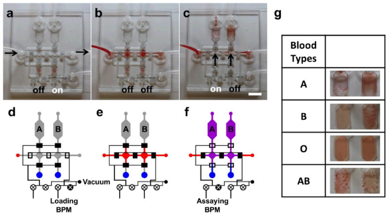
(a) An A/B/O blood-typing agglutination chip with the loading BPM “on” to allow vacuum loading of blood into the chip. (b) The blood sample is loaded into the device and then both BPMs are switched “off” to isolate all compartments. (c) Assaying BPM is turned “on” and immediately the blood sample and blood typing antibody serums are drawn and mixed in the assaying chambers by an external vacuum source. (d-f) Illustrations depicting the loading, switching, and assaying operation processes of the device. (g) Agglutination results of various blood types. (scale bar: 5 mm)
Conclusions
In this paper, a manually controllable, vacuum-enabled, on-chip bistable pneumatic microstructure (BPM) device has been presented to provide on-demand microfluidic control and manipulation. The adaptable design of the BPM allows it to be easily incorporated into a standard pneumatically actuated microfluidic network. A straightforward user-driven activation of the BPM is supported only by a vacuum source, e.g., house vacuum line, a vacuum pump, or even a manually operatable vacuum syringe, which completely eliminates complex external microcontrollers and additional electrode layers in the device. Such device integration can further enable device miniaturization and reduce the manufacturing costs. Manual switching offers a more on-demand control of the microfluidic operations through a simple push of the vacuum activation chamber (VAC) or pressure release chamber (PRC) for ON/OFF states (a footprint of only 12 mm2). This can be of extended use in a biological laboratory, a home setting, or a low-resource environment where connecting to microcontrollers can be difficult or unfeasible. BPM devices have been demonstrated in microfluidic operations, in which a 4-to-1 microfluidic multiplexor has individual channels controlled by 4 BPM devices. The on-chip control of BPM further permits portability necessary for point-of-care applications. We have demonstrated that it can be utilized in a blood-typing (A/B/O) diagnostic chip to display its clinical relevance. The on-chip BPM controls enable straightforward operation for on-demand processing of blood within the device by any user without prior trainings/experiences. Future investigation could include implementation of a low-cost imaging system with a pattern recognition algorithm to detect the red blood cell aggregates.50 In summary, the BPM offers on-demand microfluidic controls on the chip and can be easily integrated with a pneumatically powered microfluidic device while minimizing external electronic inputs. It has the potential to be incorporated into a multiplexing assay in a biological laboratory, a bedside diagnostic kit in a home setting, or even a point-of-care clinical test in a low-resource environment.
Supplementary Material
Acknowledgments
This work was in part supported by the National Science Foundation CAREER Program (ECCS-0846502) and National Institute of Environmental Health Sciences of the National Institutes of Health (P42ES004699).
Notes and references
- 1.Whitesides GM. Nature. 2006;442:368–373. doi: 10.1038/nature05058. [DOI] [PubMed] [Google Scholar]
- 2.Kovarik ML, Ornoff DM, Melvin AT, Dobes NC, Wang Y, Dickinson AJ, Gach PC, Shah PK, Allbritton NL. Anal Chem. 2013;85:451–472. doi: 10.1021/ac3031543. [DOI] [PMC free article] [PubMed] [Google Scholar]
- 3.Au AK, Lai H, Utela BR, Folch A. Micromachines. 2011;2:179–220. [Google Scholar]
- 4.Oh KW, Ahn CH. J Micromech Microeng. 2006;16:R13–R39. [Google Scholar]
- 5.Pan T, Wang W. Ann Biomed Eng. 2011;39:600–620. doi: 10.1007/s10439-010-0218-9. [DOI] [PMC free article] [PubMed] [Google Scholar]
- 6.Wagner B, Quenzer HJ, Hoerschelmann S, Lisec T, Juerss M. Proc IEEE Micr Elect. 1996:384–388. [Google Scholar]
- 7.Bosch D, Heimhofer B, Muck G, Seidel H, Thumser U, Welser W. Sens Actuat A. 1993;37-8:684–692. [Google Scholar]
- 8.Capanu M, Boyd JG, Hesketh PJ. J Microelectromech Syst. 2000;9:181–189. [Google Scholar]
- 9.Bohm S, Burger GJ, Korthorst MT, Roseboom F. Sens Actuat A. 2000;80:77–83. [Google Scholar]
- 10.Barth J, Krevet B, Kohl M. Smart Mater Struct. 2010;19:094004. [Google Scholar]
- 11.Barth J, Megnin C, Kohl M. J Microelectromech Syst. 2012;21:76–84. [Google Scholar]
- 12.Yang B, Wang B, Schomburg WK. J Micromech Microeng. 2010;20:095024. [Google Scholar]
- 13.Potkay JA, Wise KD. Proc IEEE Micr Elect. 2005:415–418. [Google Scholar]
- 14.Potkay JA, Lambertus GR, Sacks RD, Wise KD. J Microelectromech Syst. 2007;16:1071–1079. [Google Scholar]
- 15.Goll C, Bacher W, Bustgens B, Maas D, Menz W, Schomburg WK. J Micromech Microeng. 1996;6:77–79. [Google Scholar]
- 16.Lisec T, Kreutzer M, Wagner B. Sens Actuat A. 1996;54:746–749. [Google Scholar]
- 17.Huesgen T, Lenk G, Albrecht B, Vulto P, Lemke T, Woias P. Sens Actuat A. 2010;162:137–144. [Google Scholar]
- 18.Pal R, Yang M, Johnson BN, Burke DT, Burns MA. Anal Chem. 2004;76:3740–3748. doi: 10.1021/ac0352934. [DOI] [PubMed] [Google Scholar]
- 19.Pal R, Yang M, Lin R, Johnson BN, Srivastava N, Razzacki SZ, Chomistek KJ, Heldsinger DC, Haque RM, Ugaz VM, Thwar PK, Chen Z, Alfano K, Yim MB, Krishnan M, Fuller AO, Larson RG, Burke DT, Burns MA. Lab Chip. 2005;5:1024–1032. doi: 10.1039/b505994a. [DOI] [PubMed] [Google Scholar]
- 20.Shaikh KA, Li S, Liu C. J Microelectromech Syst. 2008;17:1195–1203. [Google Scholar]
- 21.Weibel DB, Kruithof M, Potenta S, Sia SK, Lee A, Whitesides GM. Anal Chem. 2005;77:4726–4733. doi: 10.1021/ac048303p. [DOI] [PubMed] [Google Scholar]
- 22.Grover WH, Skelley AM, Liu CN, Lagally ET, Mathies RA. Sensor Actuat B. 2003;89:315–323. [Google Scholar]
- 23.Grover WH, Ivester RHC, Jensen EC, Mathies RA. Lab Chip. 2006;6:623–631. doi: 10.1039/b518362f. [DOI] [PubMed] [Google Scholar]
- 24.Jensen EC, Grover WH, Mathies RA. J Microelectromech S. 2007;16:1378–1385. [Google Scholar]
- 25.Unger MA, Chou HP, Thorsen T, Scherer A, Quake SR. Science. 2000;288:113–116. doi: 10.1126/science.288.5463.113. [DOI] [PubMed] [Google Scholar]
- 26.Weaver JA, Melin J, Stark D, Quake SR, Horowitz MA. Nat Phys. 2010;6:218–223. [Google Scholar]
- 27.Irimia D, Toner M. Lab Chip. 2006;6:345–352. doi: 10.1039/b515983k. [DOI] [PMC free article] [PubMed] [Google Scholar]
- 28.Jeon NL, Chiu DT, Wargo CJ, Wu HK, Choi IS, Anderson JR, Whitesides GM. Biomed Microdevices. 2002;4:117–121. [Google Scholar]
- 29.Martinez AW, Phillips ST, Whitesides GM. Proc Natl Acad Sci USA. 2008;105:19606–19611. doi: 10.1073/pnas.0810903105. [DOI] [PMC free article] [PubMed] [Google Scholar]
- 30.Martinez AW, Phillips ST, Nie ZH, Cheng CM, Carrilho E, Wiley BJ, Whitesides GM. Lab Chip. 2010;10:2499–2504. doi: 10.1039/c0lc00021c. [DOI] [PubMed] [Google Scholar]
- 31.Nguyen TV, Duncan PN, Ahrar S, Hui EE. Lab Chip. 2012;12:3991–3994. doi: 10.1039/c2lc40466d. [DOI] [PubMed] [Google Scholar]
- 32.Duncan PN, Nguyen TV, Hui EE. Proc Natl Acad Sci USA. 2013;110:18104–18109. doi: 10.1073/pnas.1310254110. [DOI] [PMC free article] [PubMed] [Google Scholar]
- 33.Du W, Li L, Nichols KP, Ismagilov RF. Lab Chip. 2009;9:2286–2292. doi: 10.1039/b908978k. [DOI] [PMC free article] [PubMed] [Google Scholar]
- 34.Shen F, Du W, Kreutz JE, Fok A, Ismagilov RF. Lab Chip. 2010;10:2666–2672. doi: 10.1039/c004521g. [DOI] [PMC free article] [PubMed] [Google Scholar]
- 35.Shen F, Sun B, Kreutz JE, Davydova EK, Du W, Reddy PL, Joseph LJ, Ismagilov RF. J Am Chem Soc. 2011;133:17705–17712. doi: 10.1021/ja2060116. [DOI] [PMC free article] [PubMed] [Google Scholar]
- 36.Li W, Chen T, Chen Z, Fei P, Yu Z, Pang Y, Huang Y. Lab Chip. 2012;12:1587–1590. doi: 10.1039/c2lc40125h. [DOI] [PubMed] [Google Scholar]
- 37.Rhee M, Burns MA. Lab Chip. 2009;9:3131–3143. doi: 10.1039/b904354c. [DOI] [PMC free article] [PubMed] [Google Scholar]
- 38.Mosadegh B, Kuo CH, Tung YC, Torisawa YS, Bersano-Begey T, Tavana H, Takayama S. Nat Phys. 2010;6:433–437. doi: 10.1038/nphys1637. [DOI] [PMC free article] [PubMed] [Google Scholar]
- 39.Lai H, Folch A. Lab Chip. 2011;11:336–342. doi: 10.1039/c0lc00023j. [DOI] [PMC free article] [PubMed] [Google Scholar]
- 40.Cui J, Pan T. J Micromech Microeng. 2011;21:065034. [Google Scholar]
- 41.Liu HB, Gong HQ. J Micromech Microeng. 2009;19:37002–37010. [Google Scholar]
- 42.Chen A, Pan T. Biomicrofluidics. 2011;5:046505. doi: 10.1063/1.3670368. [DOI] [PMC free article] [PubMed] [Google Scholar]
- 43.Chen A, Vu T, Stybayeva G, Pan T, Revzin A. Biomicrofluidics. 2013;7:024105. doi: 10.1063/1.4795423. [DOI] [PMC free article] [PubMed] [Google Scholar]
- 44.Xing S, Harake RS, Pan T. Lab Chip. 2011;11:3642–3648. doi: 10.1039/c1lc20390h. [DOI] [PubMed] [Google Scholar]
- 45.Xia Y, Whitesides GM. Annu Rev Mater Sci. 1998;28:153–184. [Google Scholar]
- 46.Thorsen T, Maerkl SJ, Quake SR. Science. 2002;298:580–584. doi: 10.1126/science.1076996. [DOI] [PubMed] [Google Scholar]
- 47.Cooksey GA, Sip CG, Folch A. Lab Chip. 2009;9:417–426. doi: 10.1039/b806803h. [DOI] [PMC free article] [PubMed] [Google Scholar]
- 48.Linder V, Sia SK, Whitesides GM. Anal Chem. 2005;77:64–71. doi: 10.1021/ac049071x. [DOI] [PubMed] [Google Scholar]
- 49.Chin CD, Laksanasopin T, Cheung YK, Steinmiller D, Linder V, Parsa H, Wang J, Moore H, Rouse R, Umviligihozo G, Karita E, Mwambarangwe L, Braunstein SL, van de Wijgert J, Sahabo R, Justman JE, El-Sadr W, Sia SK. Nat Med. 2011;17:1015–U1138. doi: 10.1038/nm.2408. [DOI] [PubMed] [Google Scholar]
- 50.Zhu HY, Isikman SO, Mudanyali O, Greenbaum A, Ozcan A. Lab Chip. 2013;13:51–67. doi: 10.1039/c2lc40864c. [DOI] [PMC free article] [PubMed] [Google Scholar]
Associated Data
This section collects any data citations, data availability statements, or supplementary materials included in this article.


