Abstract
Purpose
SWIFT (SWeep Imaging with Fourier Transformation) is a non-Cartesian MRI method with unique features and capabilities. In SWIFT, radiofrequency (RF) excitation and reception are performed nearly simultaneously, by rapidly switching between transmit and receive during a frequency-swept RF pulse.
Because both the transmitted pulse and data acquisition are simultaneously amplitude-modulated in SWIFT (in contrast to continuous RF excitation and uninterrupted data acquisition in more familiar MRI sequences), crosstalk between different frequency bands occurs in the data. This crosstalk leads to a “bulls-eye” artifact in SWIFT images.
We present a method to cancel this inter-band crosstalk by cycling the pulse and receive gap positions relative to the un-gapped pulse shape. We call this strategy “gap cycling.”
Methods
We carry out theoretical analysis, simulation and experiments to characterize the signal chain, resulting artifacts, and their elimination for SWIFT.
Results
Theoretical analysis reveals the mechanism for gap-cycling’s effectiveness in canceling inter-band crosstalk in the received data. We show phantom and in-vivo results demonstrating bulls-eye artifact free images.
Conclusion
Gap cycling is an effective method to remove bulls-eye artifact resulting from inter-band crosstalk in SWIFT data.
Keywords: ultra-short T2 imaging, sweep imaging, bull’s-eye artifact, gap cycling
Introduction
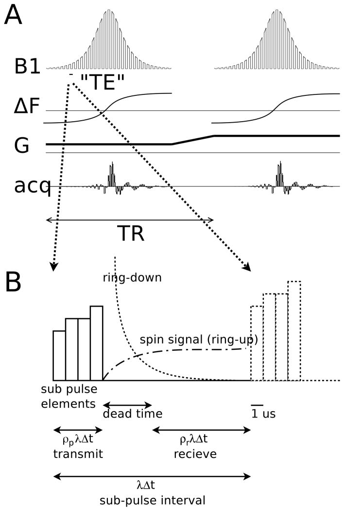
SWIFT (SWeep Imaging with Fourier Transform) (1) utilizes gapped frequency-swept pulses (2) for excitation; signal is received after a short dead interval. SWIFT can be categorized as one of the general class of short-T2 or T2* sensitive sequences (3) which possess a very short time interval between signal excitation and reception. For SWIFT this time is on the order of microseconds (Fig. 1).
Figure 1.
A. Schematic SWIFT sequence consisting of gapped frequency swept pulse with acquisition between the gaps.
B. Enlargement of one period of the gap pattern showing the transmit interval, dead time interval, and receiver interval. Ring-down of pulse voltage dissipating from the coil, and ring-up of spin signal voltage into the coil are shown (18) schematically. ρp = 0.25, ρr = 0.5, λ = 16, and Δt = 0.5 μs for all SWIFT acquisitions in this note.
Due to the gapping (gating on and off) of both the transmit pulse and the receiver acquisition interval, some signal artifacts are present in SWIFT data. This class of artifactual signal was first noted as baseline or phantom peaks with homonuclear decoupling applied during gapped signal reception. In SWIFT this artifactual signal manifests as a spherically symmetric “bulls-eye” artifact (Fig. 2A) and additional noisy background intensity in images (4,5).
Figure 2.
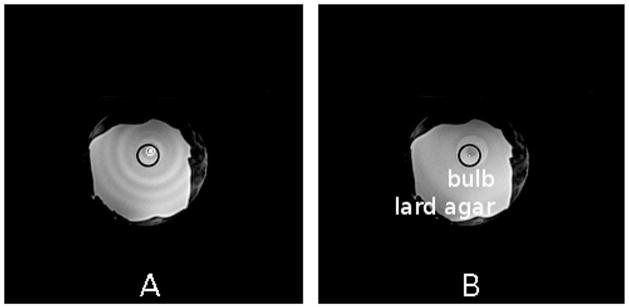
A. Uncorrected breast phantom image with intensity scaled to clearly show bulls-eye artifact of concentric rings in the slice (which are spherical shells in 3-d).
B. Corrected breast phantom image with algorithm in references (4,5). The artifact is greatly reduced but still present.
The amount of bulls-eye artifact is object, as well as SWIFT parameter dependent. Higher pulse and acquisition oversampling factors lead to reduced artifact. There is also reduced artifact when the object does not fill the field of view. As noted in reference (2), the bulls-eye artifact in SWIFT can be caused by errors in the pulse profile, which when corrected, result in less artifact. We have previously described correction algorithms for reducing bulls-eye artifact, irrespective of the source (4,5), but that leave residual artifact, or introduce additional artifact at object edges.
In the following we discuss the dominant remaining component of the bulls-eye artifact, inter-band crosstalk. We introduce a method called “gap cycling” where the position of the gaps in the SWIFT pulse are cycled in order to eliminate the bulls-eye artifact in SWIFT images.
Theory
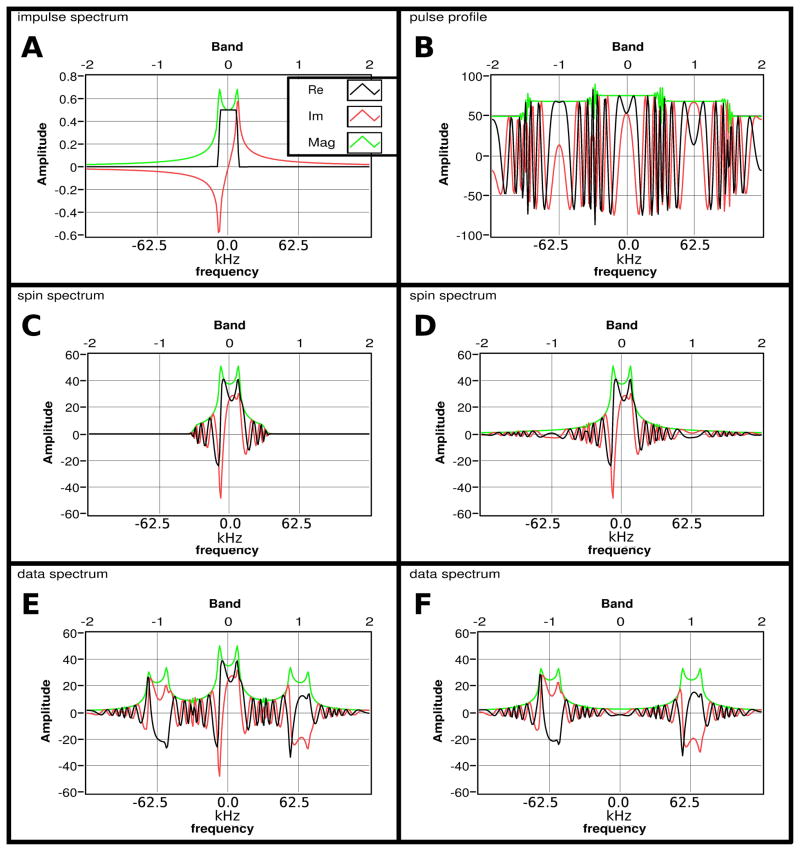
SWIFT’s transmit pulse can be viewed as an amplitude-modulated (by a square wave pattern) version of the un-gapped pulse (2). The modulation creates sidebands which extend beyond the base profile bandwidth (the “baseband,” labeled “Band 0”) of the un-gapped pulse (Fig. 3B). The goal of signal processing in SWIFT can is to recover spin signal from the baseband, which corresponds to the desired field of view. Sidebands can excite signal from spatial (or frequency) regions beyond the expected field of view. With SWIFT, the spin signal is the time domain convolution of the pulse with the spin impulse response (eq. 1) which becomes multiplication in the frequency domain. In addition, off-resonance nutation signal is present (6) that extends to the entire bandwidth of the pulse, including the gapping sidebands (Fig. 3D). This extension of the spin signal bandwidth is present (to a lesser extent) even with an un-gapped pulse (Fig. 3C).
Figure 3.
A. Impulse Spectrum H(f)
B. Gaped Pulse Profile Xgap(f)
C. Un-gapped pulse Spin Spectrum H(f) X(f)
D. Spin Spectrum R(f) = H(f) Xgap(f)
E. Data Spectrum D(f)
F. Data Spectrum D(F) with scaled R(f) subtracted
Following the notation in (2), with the impulse response of a 1-d “rect” object expressed as h(t) and the excitation pulse x(t), we have for the excited signal r(t):
| Eq. 1 |
where ⊕ is the convolution operation.
We substitute xgap(t) for x(t), where
| Eq. 2a |
| Eq. 2b |
with the duty cycle of the pulse given by ρp, and the constants λ Δt represent the period between gaps in the synthesized pulse, where λ is the integer oversampling parameter and Δt is the synthesis interval (time between points in the synthesized pulse shape.)
We have introduced:
| Eq. 2c |
which represents a shift in the position of the pulse gaps. M is a convenient integer value which represents the number of possible positions of the gap, and m is an integer representing the position. An additional constraint on M is that it should be commensurate with λ, for ease of implementation, i.e. M = λ, , etc. down to 2 but still an integer.
For simplicity we will use the same parameters for the receiver except to allow a different duty cycle ρr and neglect the delay between the center of the pulse and receiver intervals for which we compensate by linear phase correction of the data.
The gated receiver in SWIFT can also be thought of as an amplitude-modulated version of a continuous receiver. We capture the gapped receiver’s effect on the data d(t) by the equation:
| Eq. 3 |
with sr(t) = comp[(t)/(λ Δt)] ⊕ rect[(t − δt)/(ρr λ Δt)].
Substituting Eq. 1 into Eq. 3, we have:
| Eq. 4 |
which captures the effects on the data of both the gapped pulse and gapped receive interval.
It is more convenient to analyze Eq. 4 in the frequency domain. After Fourier transforming and using the Fourier convolution theorem we obtain:
| Eq. 5 |
with Sp(f) = ρp λ2 Δt2 comp(λ Δt f) sinc(ρp λ Δt f)ei2π m′ λ Δtf, and Sr(f) = ρr λ2 Δt2 comp(λ Δt f) sinc(ρr λ Δt f)ei2π m′ λ Δtf.
In each case the corresponding complex time domain function, e.g. d(t), is now represented by its complex frequency spectrum D(f). The data spectrum D(f), which is the data after reception, is shown (Fig. 3E). D(f) consists of the spin spectrum R(f) which is the signal immediately before reception (Fig. 3D), with additional overlapped replicas due to modulation by the receiver gapping. We now scale the spin spectrum to the same level as the data spectrum since the data spectrum loses signal due to the duty cycle. Subtraction of the scaled spin spectrum from D(f) shows the overlapping components remaining in the recovered baseband data spectrum (Fig. 3F.) This remaining overlapping signal (Fig. 3F, in Band 0) is the origin of the bulls-eye artifact.
Analysis of Eq. 5 is accomplished by looking at each frequency band of size sw, where sw = 1/(λ Δt).
We define crosstalk as signal originating from one band becoming mixed into other bands. We can evaluate the effects of Sp(f) and Sr(f) by looking at the components of the data spectrum:
| Eq. 6 |
where Cj,k captures the effect of convolution by Sp(f) and Sr(f); integer j indexes the signal originating from the corresponding pulse band centered at fj = j sw; and k indexes the signal received in the corresponding band of the received data at fk = k sw. For example, j = k = 0 corresponds to the signal excited by the central band of the pulse (the “pulse baseband”) and received in the central band of the receiver (the “receiver baseband”). We assume for simplicity in this analysis that the un-gapped pulse shape X(f) is band limited: X(f) lies within the bandwidth sw, as currently implemented in SWIFT.
The components Cj,k define a “crosstalk matrix.” When non-zero off-diagonal elements exist, there is mixing between bands, resulting in artifact. We evaluate Eq. 5 and put into the form of Eq. 6 and obtain:
| Eq. 7 |
We note immediately that when ρr = 1 the second sinc term is only non-zero at the center, corresponding to j = k, in which case Cj,k forms the components of a diagonal matrix. This is the no-crosstalk situation familiar from conventional continuous acquisition MRI. In the situation with gapped SWIFT, in which ρp < 1 and ρr < 1, we have non zero off-diagonal terms.
We have developed a scheme (gap cycling) where the position of gaps in the pulse and receiver are cycled relative to the un-gapped pulse shape during repeated TR periods. The pulse shape is shifted, before each TR period, relative to the position of the transmitter and receiver gates, with the intention of providing data to cancel crosstalk. We note that for the receiver baseband, k = 0, we can write:
| Eq. 8 |
which represents the cycle through the integer values of m from 0 ≤ m ≤ M − 1 and averaging the result. Note we have added the dependence on m to the crosstalk matrix component, through m′. Evaluating, we have:
| Eq. 9 |
in which the sum on the right is zero unless j = 0, since the exponential term moves evenly through a full cycle of the complex unit circle. Hence, the contribution from all other bands j ≠ 0 has been cancelled.
Methods
We acquired high resolution SWIFT images with two variations of gap cycling (M = 16) and with no gap cycling to evaluate effectiveness. The two gap cycling variations demonstrate “full gap cycling,” where each k-space view is repeated for each step of the cycle, and “rapid gap cycling,” where the cycle is applied to successive views. In rapid gap cycling, the oversampling of k-space near the origin is enough to average out the crosstalk at the spatial frequencies present. The object was a breast phantom (7) placed in our single-breast coil (8), which was modified to be SWIFT-compatible by removal of the thermoplastic basket. The breast phantoms possess uniform intensity areas that facilitate evaluation of overlapping artifacts, as well as sharp boundaries for evaluating contrast and blurring. At the center of the phantom is a spherical bulb containing water, surrounding this is Agar gel, and surrounding the Agar is a layer of lard to simulate body fat. All images were collected with 62.5 kHz baseband bandwidth (sw = 62.5 kHz), and utilize a Halton-sorted Saff vieworder (9,10) with 65,536 radial spoke views uniformly covering the 3-d sphere of k-space. Interleaved CHESS fat suppression was applied every 16 views (13). TR is 4.4 ms, and total aquisition time is 7 min including fat suppression (5 min without). The excitation pulse is HS2 R64 (2), yielding on average 32 k-space points followed by 192 additional un-gapped (full receive duty cycle) acquisition points. The images are reconstructed by gridding (11,12) from 224 post correlation (1) k-space radial points to a 5123 image matrix. One modification to the correlation procedure in (1) is that the gap cycled data at cycle position m is correlated to the shifted pulse shape corresponding to m. This produces projections with consistent linear phase in the baseband. The images have a FOV of 256 mm giving the reconstructions a nominal 0.5 mm isotropic resolution, gradient strength at this bandwidth/FOV was 0.67 Gauss/cm and rise time was 300 μs. These SWIFT images were obtained using our 4 T Agilent/Siemens/Oxford research scanner using VnmrJ 3.2 and CMRRpack v 0.45b SWIFT software (http://www.cmrr.umn.edu/swift).
In addition, brain images were acquired from a healthy volunteer using the same SWIFT parameters described above. We utilized a multi-channel TEM/Stripline (14,15) transceiver array specifically designed to be SWIFT compatible (16). The individual coil elements of the array were 200 mm in length and 50 mm in width. A 12.7 mm copper center conductor was separated from the 50 mm ground conductor by a 12.7 mm polytetraflouroethylene (PTFE) dielectric. To eliminate coil background signal from short T2 materials visible with SWIFT (16), a PTFE enclosure was designed to house the individual coil elements. The coil dielectrics were machined such that the rolled copper foil conductors could be press fitted, eliminating the use of adhesive.
Each coil was individually tuned to the proton Larmor frequency at 4 T (169.26 MHz) and matched to a 50-ohm coaxial cable. A single 8 kW power amplifier was used in conjunction with an eight-way equal-amplitude splitter for transmit. A geometric phase distribution was used to ensure a circularly polarized transmit field. Images were reconstructed using root sum of squares combination of the data from each of the 8 receive channels.
Results
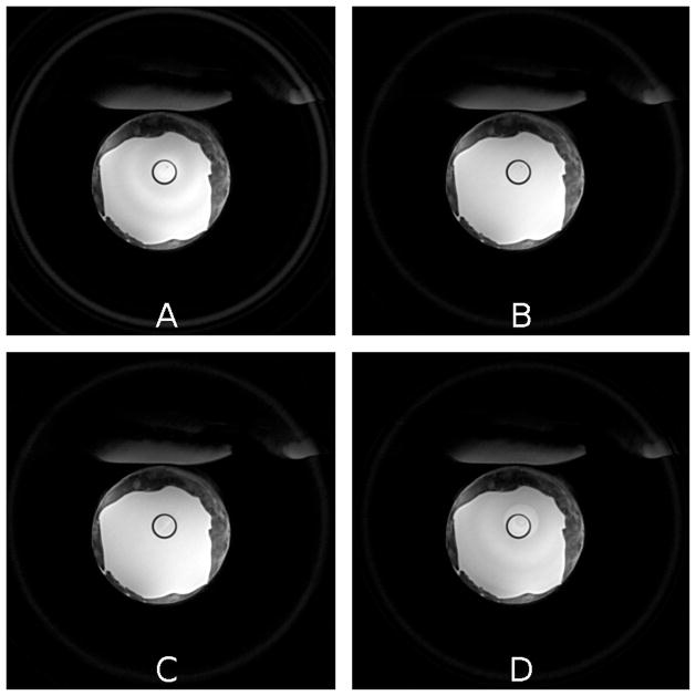
The addition of gap cycling to SWIFT experiments has largely eliminated bullseye artifact and the need for post-processing to remove residual artifact. The uncorrected image appears in Fig. 4A. Figure 4B provides the result of full gap cycling of each k-space view 16 times using the cycle M = 16, taking 16 times as long as the image in Fig. 4A. It does have somewhat higher SNR than Fig 4A from the effects of averaging (approximately 2x). Views are repeated in Fig. 4B, so both images are still undersampled and have associated noise-like undersampling artifact which puts a limit on SNR increase independent of averaging. The bullseye artifact is completely absent. Figure 4C utilizes rapid gap cycling with the same acquisition time as Fig. 4A. Figure 4D is post processing corrected from the same data as 4A, for comparison. Note the edge region of the spherical SWIFT FOV has been left (not cropped away) in Fig. 4. It appears as an inscribed circle or circles in the slices shown. The signal/artifact is related to the bulls-eye artifact in that it originates from sidebands as well. Gap cycling partially cancels this artifact (which is localized to the edge of FOV) but does not entirely cancel in the region of the frequency domain window applied during processing to reduce truncation artifacts.
Figure 4.
A. High resolution SWIFT image, 5123 matrix. No gap cycling, no correction.
B. High resolution SWIFT image, 5123 matrix, with full gap cycling using 16 acquisitions for each projection (k-space line). Bulls-eye artifact is completely eliminated.
C. High resolution SWIFT image, 5123 matrix. Rapid gap cycling, which takes the same time as image A. Bulls-eye artifact is completely eliminated.
D. Algorithm (4,5) applied to dataset from Figure 4A, artifact corresponding to the edge of the water bulb remains.
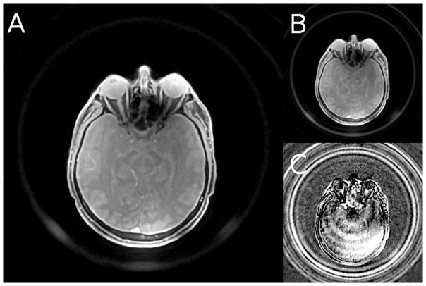
Figure 5 is an in vivo brain image taken with rapid gap cycling and no other bullseye correction. Rapid gap cycling is preferred for in vivo imaging in order to keep imaging time reasonable. No bulls-eye artifact is detectable in the image. The edge region has been left in Fig. 5 as well. Bright spots near coil elements are visible in edge region at the bottom. This is due to the coil elements being next to a partially SWIFT visible foam pad used for patient comfort.
Figure 5.
A. High-resolution brain image from SWIFT scan, 320 mm FOV, and 5123 matrix yielding 0.625 mm isotropic resolution utilizing rapid gap cycling. No bulls-eye artifact is detectable.
B. Same image parameters but acquired with no gap cycling. Bulls-eye is corrected with the algorithm in (4, 5). Shading from bulls-eye is just visible at center of image.
C. Subtraction of A from B, scaled 20x to show residual bulls-eye left in remaining B
Discussion
Gap cycling eliminates bulls-eye artifact resulting from the doubly gapped (gapped pulse and gapped receiver) SWIFT signal chain (17). As mentioned previously, other errors can also cause a spherically symmetric bulls-eye artifact, including coil ringdown (18), short T2 signal from the coil (16), pulse fidelity errors (2), and gradient timing (19), and will not necessarily be addressed by the gap cycling method. We have reason to believe that residual pulse fidelity errors not addressed by the methods in (2) can be corrected by gap cycling, especially if the number of cycle positions M is comparable to the pulse synthesis oversampling parameter λ, but a firm conclusion requires further work.
As noted previously, gap cycling is not the only way to remove or reduce bulls-eye artifact in SWIFT data. The post-processing method (4) can significantly reduce bulls-eye artifact, but can also introduce similar artifact depending on object structure. We have extended the procedure to minimize object-dependent artifact (5), but this procedure still leaves residual artifact coinciding with radii where the object has significant edge transition (Fig. 2B).
Since gap cycling does not require post processing correction, it avoids potential noise amplification and bias (due to regularization) inherent in inversion-based -processing. Additional artifact introduced by the post-processing method can be viewed as due to a bias term introduced by the regularization process and/or modeling error (20). Inversion schemes are also utilized in the methods proposed in the references (21,22).
To date, rapid gap cycling, where the gap cycle is applied to successive views, has demonstrated nearly the same performance in reducing bulls-eye artifact as the full cycle applied to each view for M = 4 and M = 16. We theorize this is due to the spatial frequencies present in the artifact being significantly lower than the resolution of the image. The oversampling at the center of k-space even in an under-sampled 3-d radial acquisition is sufficient to provide each post gridding k-space point with a full cycle. Further work is needed to establish the conditions under which rapid gap cycling breaks down, but empirically it has worked for all Halton based view orders, objects, degree of under sampling, and SWIFT pulse sequence parameters as long as ringdown is controlled.
Conclusion
We have presented the gap-cycling method to cycle the position of the RF transmit and receive intervals relative to the pulse shape for SWIFT. Gap cycling cancels crosstalk between frequency bands which results from simultaneous amplitude modulation of both the transmitted pulse and receiver interval. Gap cycling completely removes spherically symmetric bulls-eye artifact due to inter-band crosstalk, greatly improving the quality of SWIFT images.
Acknowledgments
We gratefully acknowledge NIH grant support from KL2 TR000113, R21 CA139688, S10 RR023730, S10 RR027290, P41 RR008079 and P41 EB015894. We thank Drs. Steve Suddarth and Alan Rath of Agilent for technical support. We thank Mr. Michael Tesch and Dr. Ryan Chamberlain for their collaboration on developing low level SWIFT psg code for the Agilent console. We also thank Ms. Katrina Edenfeld for detailed proofreading and editing, and Dr. Silvia Mangia for suggestions on the manuscript.
References
- 1.Idiyatullin D, Corum C, Park JY, Garwood M. Fast and quiet MRI using a swept radiofrequency. J Magn Reson. 2006;181:342–349. doi: 10.1016/j.jmr.2006.05.014. [DOI] [PubMed] [Google Scholar]
- 2.Idiyatullin D, Corum C, Moeller S, Garwood M. Gapped pulses for frequency-swept MRI. J Magn Reson. 2008;193(2):267–273. doi: 10.1016/j.jmr.2008.05.009. [DOI] [PMC free article] [PubMed] [Google Scholar]
- 3.Wehrli FW. Magnetic resonance of calcified tissues. J Magn Reson. 2013;229:35–48. doi: 10.1016/j.jmr.2012.12.011. [DOI] [PMC free article] [PubMed] [Google Scholar]
- 4.Moeller S, Corum C, Idiyatullin D, Chamberlein R, Garwood M. Correction of RF pulse distortions, with application in radial imaging using SWIFT. Toronto: International Society for Magnetic Resonance in Medicine; 2008. p. 229. [Google Scholar]
- 5.Corum CA, Idiyatullin DS, Moeller S, Garwood MG. MULTISTEP CORRECTION FOR ANGLE CONSISTENT ARTIFACTS IN RADIAL SAMPLED DATASETS. 20130084023 A1. patent US. 2013
- 6.Levitt MH. Spin Dynamics: basics of nuclear magnetic resonance. Wiley; 2001. [Google Scholar]
- 7.Bolan PJ, DelaBarre L, Baker EH, Merkle H, Everson LI, Yee D, Garwood M. Eliminating spurious lipid sidebands in 1H MRS of breast lesions. Magnetic Resonance in Medicine. 2002;48(2):215–222. doi: 10.1002/mrm.10224. [DOI] [PubMed] [Google Scholar]
- 8.Merkle H, DelaBarre L, Bolan PJ, Baker EH, Everson LI, Yee D, Garwood M. Transceive Quadrature Breast Coils and Applications at 4 Tesla. Vol. 9. ISMRM; 2001. p. 1114. [Google Scholar]
- 9.Saff EB, Kuijlaars ABJ. Distributing many points on a sphere. Mathematical Intelligencer. 1997;19(1):5–11. [Google Scholar]
- 10.Chan RW, Plewes DB. Halton Sequences for Adaptive 3D Radial Sampling. ISMRM Workshop on Data Sampling and Image Reconstruction; Sedona, AZ. 2009. [Google Scholar]
- 11.Jackson JI, Meyer CH, Nishimura DG, Macovski A. Selection of a convolution function for Fourier inversion using gridding. IEEE Transactions on Medical Imaging. 1991;10(3):473–478. doi: 10.1109/42.97598. [DOI] [PubMed] [Google Scholar]
- 12.Pipe JG, Menon P. Sampling density compensation in MRI: rationale and an iterative numerical solution. Magn Reson Med. 1999;41(1):179–186. doi: 10.1002/(sici)1522-2594(199901)41:1<179::aid-mrm25>3.0.co;2-v. [DOI] [PubMed] [Google Scholar]
- 13.Corum CA, Idiyatullin D, Snyder A, Snyder C, Hutter D, Everson L, Eberly L, Nelson M, Garwood M. SWIFT Dual Breast Imaging Sequence and Coil with Interleaved Adiabatic Fat Suppression. ISMRM 21st Annual Meeting; 2013. p. 3369. [Google Scholar]
- 14.Vaughan JT, Hetherington HP, Otu JO, Pan JW, Pohost GM. High frequency volume coils for clinical NMR imaging and spectroscopy. MAGNETIC RESONANCE IN MEDICINE. 1994;32(2):206–218. doi: 10.1002/mrm.1910320209. [DOI] [PubMed] [Google Scholar]
- 15.Adriany G, Van de Moortele P-F, Wiesinger F, Moeller S, Strupp JP, Andersen P, Snyder C, Zhang X, Chen W, Pruessmann KP, Boesiger P, Vaughan T, Ugurbil K. Transmit and receive transmission line arrays for 7 Tesla parallel imaging. MAGNETIC RESONANCE IN MEDICINE. 2005;53(2):434–445. doi: 10.1002/mrm.20321. [DOI] [PubMed] [Google Scholar]
- 16.Marjanska M, Waks M, Snyder CJ, Vaughan JT. Multinuclear NMR investigation of probe construction materials at 9. 4T. Magn Reson Med. 2008;59(4):936–938. doi: 10.1002/mrm.21566. [DOI] [PubMed] [Google Scholar]
- 17.Corum C, Idayatullin D, Moeller S, Garwood M. Doubly-gated (excitation and acquisition) effects in SWIFT. ISMRM Workshop on Data Sampling and Image Reconstruction; Sedona, AZ. 2009. [Google Scholar]
- 18.Hoult DI. Fast recovery, high sensitivity NMR probe and preamplifier for low frequencies. Review of Scientific Instruments. 1979;50(2) doi: 10.1063/1.1135786. [DOI] [PubMed] [Google Scholar]
- 19.Peters DC, Derbyshire JA, McVeigh ER. Centering the projection reconstruction trajectory: Reducing gradient delay errors. Magnetic Resonance in Medicine. 2003;50(1):1–6. doi: 10.1002/mrm.10501. [DOI] [PMC free article] [PubMed] [Google Scholar]
- 20.Hansen PC. Discrete Inverse Problems: Insight and Algorithms. Society for Industrial and Applied Mathematics SIAM; 3600 Market Street, Floor 6, Philadelphia, PA 19104: 2010. [Google Scholar]
- 21.Weiger M, Hennel F, Pruessmann KP. Sweep MRI with algebraic reconstruction. Magn Reson Med. 2010;64(6):1685–1695. doi: 10.1002/mrm.22516. [DOI] [PubMed] [Google Scholar]
- 22.Corum CA, Moeller S, Idiyatullin DS, Chamberlain R, Garwood MG. SIDEBAND PROCESSING FOR MAGNETIC RESONANCE. 20130043867. patent US. 2013


