Abstract
Bistable systems play an important role in the functioning of living cells. Depending on the strength of the necessary positive feedback one can distinguish between (irreversible) “one-way switch” or (reversible) “toggle-switch” type behavior. Besides the well established steady state properties, some important characteristics of bistable systems arise from an analysis of their dynamics. We demonstrate that a supercritical stimulus amplitude is not sufficient to move the system from the lower (off-state) to the higher branch (on-state) for either a step or a pulse input. A switching surface is identified for the system as a function of the initial condition, input pulse amplitude and duration (a supercritical signal). We introduce the concept of bounded autonomy for single level systems with a pulse input. Towards this end, we investigate and characterize the role of the duration of the stimulus. Furthermore we show, that a minimal signal power is also necessary to change the steady state of the bistable system. This limiting signal power is independent of the applied stimulus and is determined only by systems parameters. These results are relevant for the design of experiments, where it is often difficult to create a defined pattern for the stimulus. Furthermore, intracellular processes, like receptor internalization, do manipulate the level of stimulus such that level and duration of the stimulus is conducive to characteristic behavior.
Keywords: Systems biology, cell signalling, multistability, transient behavior, bounded autonomy
I. INTRODUCTION
Living cells must continually sense their external and internal environment and induce changes on the basis of this information. In this way they are able to adapt to their environment, continue or stop their development, and form more complex structures through intercellular communication (Wolkenhauer et al., 2005b). This processing of information in living cells is carried out by signalling networks (Downward, 2001; Wolkenhauer and Mesarović, 2005). The character of information and the corresponding responses include a wide range of physical and chemical quantities, changes in temperature, pressure, water balance, concentration gradients, and pH-level.
Within these networks, information is transmitted by dynamic changes in protein concentrations. Besides continuously varying signals, some cellular processes lead to discontinuous, switch-like responses (Bhalla and Iyengar, 1999; Ferrell and Xiong, 2001; Huang and Ferrell Jr., 1996; Melen et al., 2005). Such a bistable system toggles between two discrete, alternative stable steady states, in contrast to monostable systems (Ferrell Jr., 1998; Ferrell Jr. and Machleder, 1998; Markevich et al., 2004). Their separated branches of the steady-state response allow the implementation of switches in biochemical networks. Other examples include cell cycle oscillations and mutually exclusive cell cycle phases (Pomerening et al., 2003; Tyson, 1991; Tyson et al., 2002) as well as the generation of biochemical “memory” (Eißing et al., 2004; Lisman, 1985; Xiong and Ferrel Jr., 2003). Due to their properties, bistable systems also play an important role in development (Melen et al., 2005), cell differentiation, and evolution of biological systems (Laurent and Kellershohn, 1999; Thomas and Kaufman, 2001).
Bistability may arise in signalling pathways that contain at least one feedback loop or a combination of feedback loops whose sum of signs is positive with respect to the considered response component (Cinquin and Demongeot, 2002; Thomas, 2004). The existence of positive feedback is a necessary but not a sufficient condition for bistability (Angeli et al., 2004). A standard graphical test in the phase plane can be used to analyze these conditions, especially the parameter values, under which the system is bistable. Nevertheless, the analysis of complex positive-feedback systems is difficult. In (Angeli, 2006; Angeli et al., 2004), a method to investigate systems with arbitrary order was presented within the framework of monotone systems. In this so-called ‘open-loop approach’, the feedback loop is cut and treated as an additional input. The system can then be treated as a simple input/output system. A generalization to more complex feedback structures is possible, if the feedback can be summed up in one single apparent feedback loop.
Positive feedback in signalling pathways has to be highly nonlinear in order to create two asymptotically stable steady states in the system. In biological signalling networks such behavior is often realized through ultrasensitive structures, such as covalent modification cycles (Goldbeter and Koshland Jr., 1981; Tyson et al., 2003), protein cascades with multiple steps (Asthagiri and Lauffenburger, 2001; Bhalla and Iyengar, 1999; Heinrich et al., 2002; Huang and Ferrell Jr., 1996), or inhibitor ultrasensitivity (Ferrell Jr., 1996; Thron, 1994). A simple autocatalytic reaction can also bring about bistability (Schlögl, 1972).
In the present paper we do not focus on the investigation of possible mechanisms creating multistability but investigate the dynamics of a bistable system independent from the underlying mechanism. Hence, we assume, that the considered system is bistable or in general multistable. Furthermore, we are not interested in a general investigation of parameter dependencies but focus on stimulation patterns that influence the bistable behavior as this is relevant for the design of cell signalling experiments.
The paper is organized as follows. In Section II, we introduce a minimal model to discuss dynamic properties of bistable systems and provide necessary definitions. In Section III, steady state properties of bistable systems are reviewed. In the following section we discuss the dynamic behavior of bistable systems, using the introduced model of a bistable system. The concept of “bounded autonomy” is defined for the system considered in Section V. From the example we derive characteristic time scales, which are important for the signal duration of the stimulus and the system’s low-pass filter characteristics. The results obtained in the previous sections are generalized to multistable systems. Finally, we summarize our results in the last section.
II. THE MODEL
Throughout this study we use as an example the mutually-activated enzyme network, as described in (Tyson et al., 2003) (Fig. 1). In this network, a linear system is coupled with a sigmoidal system through a positive feedback loop. The corresponding mathematical representation is given as
FIG. 1.
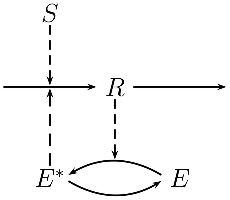
Graphical representation of the system used as a case study to discuss multistability. The response component R is produced in a linear pathway, induced by an external stimulus S. The response component activates the enzyme E, which in turn facilitates the production of R through a positive feedback loop. This mechanism has been described as “mutual activation” (Tyson et al., 2003). The modification of the enzyme E follows a covalent reaction scheme (Goldbeter and Koshland Jr., 1981; Tyson et al., 2003).
| (1a) |
| (1b) |
where the response component is R(t) and the external stimulus or input is S(t). For notational convenience, we do not show the dependence on time for these two variables from now on. The kinetic constants ki and the Michaelis-Menten constants Ji (Cornish-Bowden, 2004; Segel, 1993) determine the chemical properties of the involved biochemical species. Further, R(0) ≡ R0 denotes the initial condition, and G(·) the Goldbeter-Koshland function (Goldbeter and Koshland Jr., 1981; Tyson et al., 2003) defined for system (1) as:
| (2) |
where
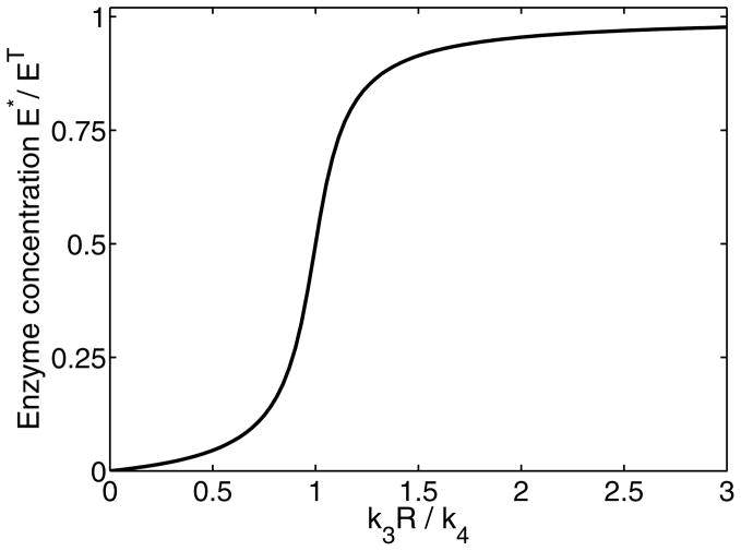
This function describes the concentration of the modified form E*(R) as a steady state equation. It is frequently used considering (de)modification cycles, see Fig. 1 and Appendix A. The Goldbeter-Koshland function (2) has a typical sigmoidal shape, as shown in Fig. 2. Due to its highly nonlinear behavior it can cause multiple steady states in the investigated system (1). The use of the Goldbeter-Koshland function assumes that the modification of enzyme E is much faster than the change of the response component R. This allows us to use a quasi-stationary approximation (Millat et al., 2007). From Eq. (1a), the production rate of R is separated into a stimulus dependent and enzyme dependent contribution. Due to the positive feedback loop the production rate is regulated in an autocatalytic fashion. More on modeling of activation/deactivation cycles in signaling pathways can be found in (Salazar and Höfer, 2006).
FIG. 2.
The ratio of modified enzyme and its inactive form as function of the response R considering the Goldbeter-Koshland function (2). The sigmoidal behavior is highly nonlinear and provides a continuous switching behavior at k3R = k4. The parameters are chosen as specified in Appendix E.
We consider two types of input stimulus S. The first one is a step input defined as:
| (3) |
where Smax is the signal amplitude or strength, and u(t) represents the step function (Bracewell, 1999) with u(t) = 1 for t ≥ 0, and u(t) = 0 for t < 0.
For a cellular environment, one would not expect a stimulus that maintains a constant level over prolonged periods of times. If changes in the stimulus are much slower than the response of the system one can assume a quasi-stationary state (Millat et al., 2007) but in many cases one deals with various input profiles. We therefore also analyze the system using a pulse input:
| (4) |
where Δτ > 0, is the pulse width or duration.
In the following section, we review steady-state properties of the bistable system (1). The nominal parameter values used for numerical simulations can be found in Appendix E.
III. STEADY-STATE PROPERTIES
In this section, we briefly summarize the steady state properties of the bistable system we are considering. We obtain the steady state of system (1) with a step input (3) as a solution of the balance equation,
where production and degradation rates are balanced such that no macroscopic net change is measurable. Specifically, for system (1) the balance equation can be written as,
| (5) |
where RSS refers to the steady states.
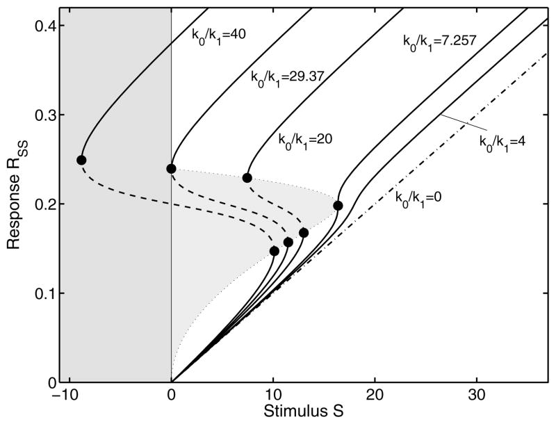
The steady-state properties of a dynamic system provide us with a wide range of information on bifurcation, stability and control analysis (Fell, 1997; Heinrich and Schuster, 1996). For complex reaction networks, the balance Eq. (5) can have multiple solutions. The classification of the associated roots and their relevance cannot be determined analytically, but requires knowledge of the particular biological system under consideration. Since we are dealing with measurable physical quantities, i.e., biochemical concentrations that are non-negative, the feasible solutions should be real and non-negative. A mathematical proof for the existence of steady states and their stability analysis is given in (Tyson and Othmer, 1978). The steady states, as a function of a step input with stimulus strength Smax, can be computed by simply solving Eq. (5) numerically and selecting only the feasible solutions. This is visualized in the step stimulus response curve (Fig. 3) for various feedback strengths. As seen from the figure there are either one or three steady states for different parameter values.
FIG. 3.
Steady state step stimulus response curves for different feedback strengths (k0/k1). The system behavior changes from a one-way switch to a toggle switch and finally to a monostable system. The second curve from the left, separates the toggle-switch from a one-way switch. At Smax = 0 there is a second critical point. The third curve is a typical example for hysteresis. If we further decrease the feedback strength, the critical points coincide and finally disappear. For weak positive feedback the system is monostable and asymptotically approaches the response curve for k0/k1 = 0, representing the step stimulus-response of a linear system. Additionally, we plot the unstable region in gray. In order to represent the complete course of all curves we extend the abscissa to negative stimuli, which is of course physically irrelevant.
On further investigation, we realize that for bistable behavior, the balance equation must have at least three biophysically realizable solutions. Of these, two stable branches are separated by an unstable branch as shown in the bifurcation plot (Fig. 3). This unstable branch plays an important role in the dynamics of bistable systems. From these considerations, the characteristic Eq. (5) has to be a polynomial of at least third degree, or a highly nonlinear function. With a proper chosen set of parameters, the sigmoidal Goldbeter-Koshland function (2) fulfils this condition. It is clear from Fig. 3 that we can define
| (6) |
where we drop the direct dependence on Smax for representational convenience. RSU and RSL are the stable upper and lower steady state respectively and RUN is the middle unstable state (indicated by the dashed line in Fig. 3).
What the bifurcation diagram does not reflect is the transient behavior between the previous and the new steady state. The transient phase plays an important role in various biological processes, including cell differentiation (Laurent and Kellershohn, 1999) and apoptosis (Aldridge et al., 2006).
As the feedback strength in system (1), represented by the ratio k0/k1, is varied, the steady state step response has different characteristics (Fig. 3). If the ratio is k0/k1 ≥ 29.4, the system acts as a one-way switch. Once activated it remains in this state. In an intermediate range of the feedback strength, the system is a reversible switch and shows hysteresis-like behavior (Angeli et al., 2004; Ferrell Jr., 1998; Tyson et al., 2003). In both cases, the solution of balance Eq. (5) consists of three branches (Tyson and Othmer, 1978), two stable ones (solid lines for RSU and RSL), separated by an unstable branch (dashed lines for RUN), as described before. From a biochemical point of view the stability of the response component is determined by the partial derivative or the Jacobian of system (1) evaluated for a given parameter set (for instance nominal parameter set in Appendix E) and a specific Smax (Gray and Scott, 1994),
| (7) |
where the stable steady states are minima of this function and unstable states are maxima (see Fig. 4). The Jacobian J is an implicit function of Smax since system (1) is affine. A small perturbation in response component R will relax back to the former steady state if Eq. (7) is negative. The corresponding steady state and its neighborhood are stable (Schlögl, 1971). Otherwise, the system is unstable and an infinitesimal fluctuation moves the system to one of the neighboring stable states.
FIG. 4.
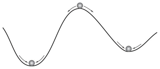
Schematic representation of the stability criterion (7). The stable states corresponds to minima of the Jacobian and unstable states to a maximum. Small perturbations of a stable steady return the system back to the same state, whereas the system moves from the unstable state into one of the stable states.
For a one-dimensional system as in (1), at steady state (RSS), the Jacobian represents the eigenvalue of the system linearized around this state. Using MAPLE (Maplesoft, Waterloo, Ontario) we computed the Jacobian (7) at the steady states with nominal parameters (Appendix E) and for stimulus Smax ∈ [0, 40]. While the real part of the eigenvalue is negative for RSU and RSL, indicating stability, the real part of the eigenvalue is positive for RUN, indicating instability. The three branches are separated by critical or bifurcation points, where the system’s behavior changes abruptly. The critical points define a range where no stable steady state exists (presented by the gray area in Fig. 3).
Note how varying the feedback strength impacts on the system’s behavior. For instance, when we weaken the feedback strength, the system eventually loses its bistable nature. In the limit of vanishing feedback k0/k1 → 0, the system (1) is of first-order and linear. This limit also defines the asymptotic behavior for small external stimuli, where only a small amount of enzyme E is modified (corresponding to weak feedback). Note that we did not change the properties of the enzymatic modification cycle but only modified k0 to vary the feedback strength. The modification cycle of the system is considered ultrasensitive for all parameter sets used.
The following section introduces dynamic characteristics of bistable systems.
IV. DYNAMIC BEHAVIOR
The response of biological systems to changing environmental or cellular conditions is a dynamic process (Wolkenhauer et al., 2005a). The system’s transient relaxation into a new steady state depends on the previous state of the system, the input strength and duration, as well as, on the structure and the kinetic parameters of the biological system under consideration.
In multistable systems the transition between the different stable branches is of special interest. Extending the discussion from Section III, we use the terms “lower branch” and “upper branch” for the bistable system to distinguish between both stable solutions of the balance Eq. (5). Note, the assignment of an “off” and an “on”-state depends on the biological system, not the mathematical solutions. In the following section we discuss the transient response to an external stimulus S. The kinetic parameters and total concentrations remain unchanged (see Appendix E). Initially we investigate the transient response of a step input, followed by that of a pulse input. In the latter case, the change of stimulus allows us to separate the dynamics into periods with different but constant values of the stimulus S (Bracewell, 1999).
Step Response of the Bistable System
Following (Tyson et al., 2003), for a given set of parameters, initial condition R0, we define the critical stimulus S = Scrit*u(t) as the smallest step stimulus amplitude that changes the cellular response “abruptly and irreversibly”. Any Smax > Scrit is labeled supercritical stimulus. In contrast, a subcritical stimulus refers to an amplitude that does not affect such change in the cellular response, i.e., Smax < Scrit.
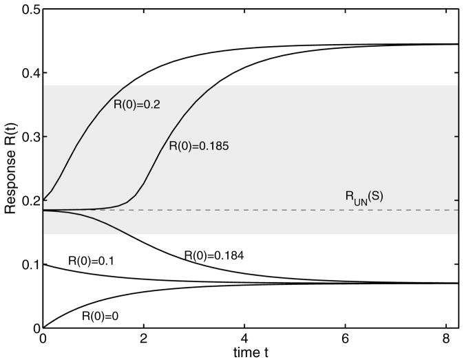
To begin with, we investigate the dynamic behavior of system (1) for a specific subcritical stimulus Smax < Scrit with different initial conditions (Fig. 5). Depending on the initial concentration R0, the transient response signal tends to either the lower or the upper stable branch. The considered system therefore has some form of memory. The unstable solution RUN of balance Eq. (5) acts as a separatrix between both behaviors. If the initial concentration is lower than the unstable state, the response approaches the lower stable branch. In the other case, the new steady state is located on the upper branch. The stable states act as attractors and the unstable state as a repeller. This property of an unstable state will become important for our subsequent discussion. Of course, for a supercritical stimulus Smax > Scrit, the concentration of the response component always tends to the upper stable state. Additionally, we plot in the figure the forbidden region, where no stable solution of balance Eq. (5) exists. Because system (1) acts as an one-way switch for the used nominal parameters, this region is defined through the sum of the unstable area and the range of irrelevant solutions, see also Fig. 3.
FIG. 5.
Steady state response for a subcritical signal Smax < Scrit for different initial conditions. The unstable state is a separatrix. The gray area denotes the forbidden region.
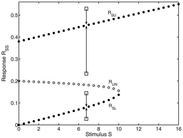
Fig. 6 shows us how we can use a given initial condition R0, to determine the critical stimulus Scrit from the middle segment of the curve (corresponding to the unstable steady state). Consequently, for R0 < RSL, or for RSL < R0 < RUN, the trajectory of R(t) converges to RSU asymptotically. In essence, for a given R0 there exists a corresponding Scrit.
FIG. 6.
Relationship between initial condition R0 (rectangles), stable steady states (RSU, RSL), unstable steady state (RUN) and the corresponding critical value of step amplitude Scrit. Arrows indicate the asymptotic convergence of trajectories over time, starting from a given initial condition. Nominal parameters have been assumed (Appendix E).
Pulse Response of the Bistable System
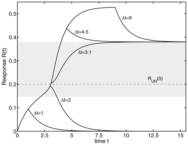
Apart from stepwise constant stimuli, biological systems often have to respond to transient signals. Thereby, the response to pulse-like signals is of special interest. The reason for such a signal may be a perturbation in the environment, degradation of ligands (Lauffenburger and Linderman, 1993), receptor internalization (Madshus, 2004) amongst others. The system response for a pulse input (4) is shown in Fig. 7 for the system with the nominal parameters. Switching depends on R0, Smax and Δτ. Starting with initial condition R0 = 0, we apply a supercritical pulse stimulus Smax = 14 for varying pulse widths Δτ. For signal durations Δτ < 3.1 the response asymptotically converges to zero. If the signal duration exceeds this limit, the response approaches a steady state on the upper branch and remains on this branch. This pulse duration is defined as the critical pulse duration Δτcrit, and the corresponding pulse amplitude is defined as Scrit. We therefore note that it is the combination of signal strength and signal duration which defines the steady state. Pulses which do not fulfill this criterion cannot change the state of the system. The bistable system cannot resolve these pulses and acts as a low-pass filter. Given an initial state R0, we can find a combination of Scrit and Δτcrit, such that the system switches to the upper branch (and asymptotically converges to the upper steady state). For the nominal parameters, the system asymptotically converges to RSU = 0.38, which corresponds to Smax = 0 (see Fig. 6).
FIG. 7.
Transient pulse response of R to a supercritical stimulus S > Scrit as a function of the signal duration Δτ from the origin. After Δτ the external stimulus returns to its initial value. The grey region denotes the forbidden area where no stable solution exists. The critical pulse duration for a critical pulse with amplitude Smax = 14 is Δτcrit = 3.1.
In the next section, we discuss the characteristics of the switching surface obtained for the pulse response of the system for varying {R0, Scrit,Δτcrit}, in terms of the concept of bounded autonomy for a single level system.
V. BOUNDED AUTONOMY IN SINGLE LEVEL SYSTEMS
Bounded autonomy has been described in (Mesarovic et al., 2004) for multi-level systems where the higher level does not intervene to modify the behavior of the lower level system as long as the system is ‘performing’ at a ‘satisfactory’ level, and intervenes to modify the behavior of the lower level only in order to bring the complex system performance to a satisfactory level. We will adapt this concept to a single-level system using the concept of a switching surface.
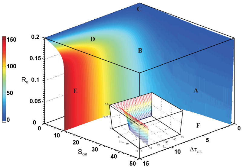
To this end, for a pulse input (4) we plot in three dimensions the critical stimulus Scrit, pulse width or duration Δτcrit, and initial condition R0 as represented in Fig. 8. The plot was generated by fixing Smax and Δτ and gradually increasing R0 in the dynamic system simulation till the system pulse response switches from the lower branch to the upper branch in steady state. The value of the pulse strength is then the critical stimulus Scrit and the pulse duration is the critical duration Δτcrit for the given initial condition R0. The simulation period was 15 units of time with ranges for input and initial condition was as follows: Δτcrit ∈ [0, 15] with resolution 0.01; Scrit ∈ [0, 50] with resolution 0.01; and for R0 ∈ [0, 0.2] with resolution 0.001 which comes to maximum of billion dynamic simulations. These were done using MATLAB (The MathWorks, Natick, MA) with ‘ode45’ equation solver on a 2.81 GHz, 2 GB RAM Windows based machine with AMD Athlon processor and numerical accelerator card. In reality, the number of simulations conducted were 2.073 million points on the switching surface, since only simulations for values of R0 below the switching surface were considered. Lower resolution simulations (less than 100, 000 points) resulted in artifacts that disappeared when high resolution simulations were conducted.
FIG. 8.
Switching surface of the system’s pulse response to an initial condition R0, critical stimulus Scrit and critical pulse duration Δτcrit. Regions A–F represent characteristics of the switching surface. Heatmap color refers to the critical power Pcrit. A contour plot included in the inset indicates further details about the surface.
We now define the input signal power as the integral of the stimulus over time as:
| (8) |
Particularizing this for the pulse input with Pcrit as the power,
Then the critical power represents the “dosage” or input needed for the system to switch assuming that the objective is to induce the system to switch. The color “heat-map” in Fig. 8 indicates this critical power as a function of R0, Scrit, and Δτcrit. Below we describe regions of the switching surface in Fig. 8. There is a deadband for Δτcrit ∈ [0, 0.1] since the system does not switch for pulse width equal to zero, and the pulse amplitude is not high.
Region A: Low values of R0 and Δτcrit, require a high value of pulse amplitude or Scrit for switching.
Region B: With ever so slight increase in Δτcrit and for the same low values of R0, a much lower value of Scrit is needed for switching.
Region C: At a fixed, but high level of R0 (for example R0 slightly below 0.2) the switching is independent of critical pulse duration (Δτcrit = [0.1, 15]), and, only a low level of stimulation amplitude Scrit < 8 is needed for switching. Also for the Scrit axis, for 8 > Scrit, the switching surface falls at a nearly constant rate of 0.04 along the initial condition range 0.2 > R0 > 0.18.
Region D: As we move along the Scrit axis, for 10 > Scrit > 8, the switching surface slopes faster along the initial condition range R0 = [0.15, 0.18).
Region E: Between 10.4 > Scrit > 10.1, the switching surface rapidly falls indicating that the system can switch for smaller values of R0 for given Δτcrit and ever so small increase in Scrit, finally having the ability to switch at R0 = 0.
Region F: This flat region indicates that with initial condition R0 = 0, the system can switch for a wide range of a rectangular area spanned by Scrit ∈ [10.4, 50], and Δτcrit ∈ [1, 15], and bounded by the curve formed by the intersection of the switching surfaces and the Scrit and Δτcrit plane.
Further, a contour plot given in the inset in Fig. 8 indicates a lip that is formed at Region C, and also illuminates the shape of the switching surface. If the system state and the stimulus is below the surface indicated in Fig. 8 (except Region F), then the system response stays within bounds and reverts back to the zero state eventually. If however, the system state and the stimulus are at or above the switching surface then the system state switches to a higher value than the initial state. This phenomenon is interpreted as bounded autonomy for single level systems, i.e., the system is autonomous below the switching surface, and is dependent on the system state and input stimulus combination to switch to a different state.
One philosophical approach to understanding biology is to consider the biological system purposive or teleological. Performance is then related to the objective of the system. For instance constitutive activation (such as switching) of a key system state could be implicated in development of cancer, e.g., JAK2 constitutive activation is implicated in chronic myelogenous leukemia (CML) in murine models. To consider a system to be performing with the objective of not becoming cancerous, then constitutive activation resulting from bistability needs to be avoided. If the value of a parameter (say a rate constant) is bounded and not triggering switching then the system can be defined to be performing at a satisfactory level. Thus within these bounds of the parameter the system behavior remains non-cancerous and thus follows the organizing principle of bounded autonomy.
Critical Power for the Bistable System with a Pulse Input
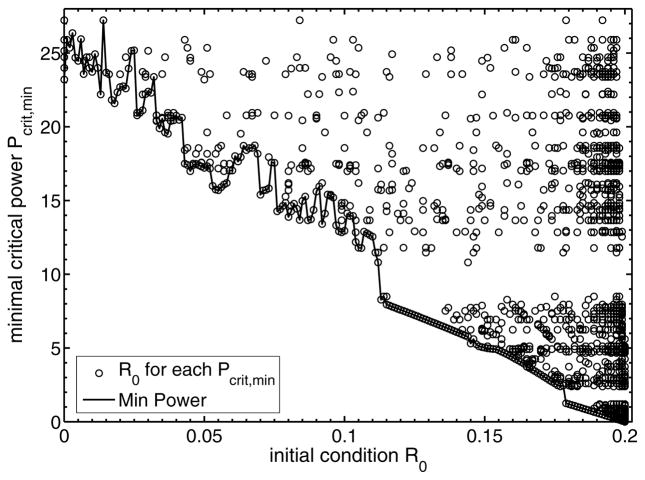
Fig. 9 depicts the minimum critical power required to switch from a given initial condition R0, i.e.,
FIG. 9.
Plot of the minimum critical power (Pcrit) required for the system to switch from a specific initial condition R0 and pulse input.
The trend in Fig. 9 indicates that as the initial condition increases the amount of minimum critical power needed to switch to the upper branch decreases. This follows from the fact that an increase in the initial response component decreases the displacement between R0 and the unstable state. As one can see in Fig. 7, the chemical activity of the considered system is high in the forbidden region. Hence, it takes less time to bridge the gap between the initial value and the unstable state.
Interestingly, for low values of R0 < 0.1, the curve of the Pcrit,min fluctuates (Fig. 9). The exact reason for such fluctuations is hard to pinpoint. We recognize that analytically finding the minimum critical power is not possible. Further we note that the simulated range of the input amplitude and duration limits the numerically computed minimum critical power, which we have verified numerically. Hence Fig 8 is indicative. Also, given a Pcrit,min value, the open circles indicates the appropriate R0 to reach this critical minimum power. One interpretation is that given the state of the biological system (indicated by the initial condition) the minimum dosage (indicated by the power) needed for the system to switch can be read off from the curve.
VI. ESTIMATION OF CRITICAL SIGNAL DURATION
As the numerical analysis of system (1) with a step input shows, not only signal amplitude Smax defines the final state (see Eq. (5)). In this section we estimate the critical duration of stimulus Δτmin, which is the minimal time a step stimulus has to be applied to reach the unstable state given that the initial condition of the system R0 < RUN. Unfortunately, system (1) cannot be solved analytically due to the complexity of the Goldbeter-Koshland function (2).
For the sake of simplicity but without loss of generality, we restrict our discussion to the one-way mutual activation switch (1) and investigate the transient changes between the lower to the upper branches for an supercritical stimulus. We assume a small concentration of the response component to begin with. We can then expand the Goldbeter- Koshland function (2) with respect to the response component R. The derivation is given in Appendix A. This is then used to replace the complex Goldbeter-Koshland function G(·) with the leading first-order term of the expansion, yielding the linear differential equation
| (9) |
Due to the positive feedback loop, there is now an additional contributing term, which depends on the concentration of R. This term reduces the rate of degradation, where the constant C1 follows from the Taylor expansion (A2). The resulting linear differential equation can be solved analytically and we obtain for the critical signal duration
| (10) |
where we introduce the new effective rate constant
| (11) |
and the steady state concentration .
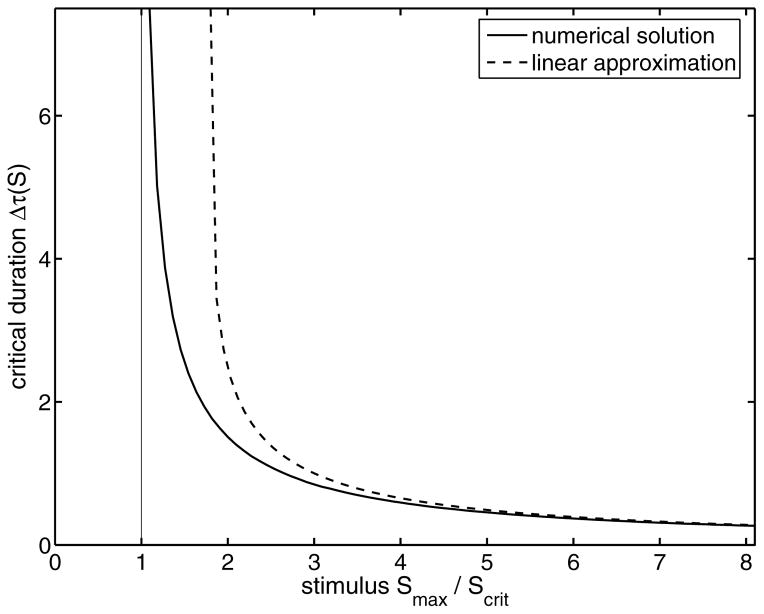
In Fig. 10, the approximation (10) is compared to a numerical analysis of system (1). Due to an underestimation of the positive feedback contribution, the approximation deviates for weak stimuli from the intrinsic critical duration time Δτmin. Here, the nonlinear character of the Goldbeter-Koshland function (2), describing the feedback dependence, is important. The inclusion of higher orders of the series expansion (A2) would provide a better description for weak supercritical signals, but the resulting differential equation becomes nonlinear and cannot be solved with respect to the critical duration. For strong signals both representations tend to a common asymptote (see Appendix C)
FIG. 10.
The critical signal duration Δτmin as a function of the step stimulus amplitude Smax. We compare the results of a numerical calculation (solid line) with the linear approximation (10). For weak supercritical stimuli the approximation differs from the numerical result because of the underestimated positive feedback contribution in the production rate of the response component. For higher levels of stimulus, the approximation agrees with the numerical solution.
which is inversely proportional to the production rate k1 Smax and direct proportional to the displacement between unstable state and the initial state.
VII. SIGNAL POWER
In Section IV, we demonstrated that for system (1) with an initial condition lower than the unstable equilibrium R0 < RUN, and a step input, there exists a minimum input amplitude Scrit, for which the system switches to the upper stable equilibrium. Next we define Δτmin as the minimal necessary signal duration of a supercritical signal Scrit such that response reaches the unstable equilibrium R(Δτmin) = RUN. From our discussion in Section IV, it is clear that
It is now appropriate to modify the signal power definition in (8) and extend this analysis for a step input for the above case by defining the signal power needed Pmin as,
| (12) |
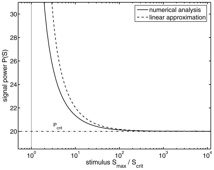
A comparison of the numerical analysis for the nonlinear system (1) and its linear approximation (9) is shown in Fig. 11. The signal power increases for weak supercritical signals and tends to infinity in the limit Smax → Scrit. On the other hand, for strong stimuli the signal power approaches a constant limiting value Pmin. We are now going to calculate this limiting value. Towards this end, we again use the logarithmic expansion of the critical duration time (10) (Appendix C) and neglect all terms higher than first-order with respect to the stimulus S. Due to the stimulus-dependent prefactor of Eq. (10) the remaining dependencies on the signal cancel out so that we obtain the constant limiting signal power (see Appendix D for a derivation)
FIG. 11.
Semilogarithmic plot of the signal power as a function of the external stimulus for the nonlinear system (1) (solid line) and for the linear approximation (9) (dashed line). The dash-dotted line is the minimal signal power (13) following from the strong stimuli approximation. The line defines the minimal signal power required to switch the system between the stable states.
| (13) |
This defines the minimal signal power which is necessary to push the system from the lower to the upper state. It depends only on the difference between the unstable and the initial state, and the kinetic parameter k1. The critical power decreases with decreasing displacement of initial and unstable state. This is qualitatively equivalent to the critical power for pulse input in Fig. 9, where we investigated the critical power as function of the initial state for a fixed stimulus. It is interesting that there is no contribution of the feedback loop and the degradation rate to the derived minimal signal power. For weaker supercritical stimuli as in Fig. 9, where the positive feedback is dominant, this leads to an increase of the necessary signal power. On the other hand, this will decrease the sensitivity of the system in the neighborhood of the critical point, ensuring a proper decision on the basis of stable stimulus and not based on small fluctuations.
VIII. GENERALIZATION TO MULTISTABLE SYSTEMS
In the last section we investigated and estimated the properties of bistable systems. In this section, we extend our findings to multistable systems which have more than two stable branches. Some general features of the dynamical behavior of multistable system can be directly inferred from bistable systems investigated in the previous sections. To this end, we consider multistable systems as a combination of neighboring bistable systems. Then the transition between neighboring stable states depends on the combination of external stimulus and its duration. As in the case of bistable systems, each pair of of stable branches is separated by an unstable branch. This unstable branch has to be exceeded also in the case of multistable systems. Then the system approaches the neighbored stable branch, even if the stimulus switch back to a level corresponding to a steady state at the former branch. It should be noted, that a signal is required which has a stable solution on both branches. Furthermore, in our discussion about bistable systems we use a “toggle switch” as an example which switches irreversibly. Reversible bistable and multistable can also switch back to lower stable branch. Also, the separating unstable branch determines the characteristic signal duration.
Even if the analytical analysis of multistable systems is more complex than our example of a mutually activated system (1), from a mathematical point of view and from their diversity of initial conditions, we are able to transfer directly some dynamical properties of bistable systems. The transient switching between neighboring stable branches underlies the same qualitative restrictions as in the bistable system.
IX. DISCUSSION
Multistable systems play an important role in the function and regulation of biological systems. Depending on the values of kinetic parameters the cellular system can have multiple stable steady states, which are separated through unstable ones. Whereas the final state of the system is determined by the stable state, the dynamic response depends on transient properties of the corresponding stimulus and is strongly affected by the unstable state between the two neighboring stable branches. The transition between the stable branches is triggered by changing the signal strength of the stimuli in case of a step input. A supercritical signal with respect to the current stable branch leads to a jump to the next stable branch. If the system is a reversible switch, a subcritical signal forces the system back to a lower branch until the lowest one is approached.
Note that the widely used stimulus-response analysis does not provide us with information about the dynamics of the investigated system. The presented steady state, as a function of a step input stimulus, is formally reached after an infinite time. From a dynamic perspective this means, the system is much faster than the variation of the stimulus. In biological systems, say in signal transduction, we deal with the reverse situation, where the environmental changes are faster or in the same time scale as the intrinsic time the system requires to adapt to the new context. The importance of studying dynamical properties of bistable systems has recently been shown in the context of apoptosis (Aldridge et al., 2006), where crucial decisions are determined by the transient activation of active caspase-3. How the choice of time-delays incorporated into the mathematical models change the dynamic behavior without influencing the steady state of the considered system was demonstrated in (Veflingstad et al., 2005). As a consequence, the consideration of the dynamic behavior is important as well as the consideration of steady states to understand the function and the structure of a biochemical network. Different biochemical systems may have qualitatively equal steady states, but their transient behavior can discriminate between biologically favorable models from unfavorable ones.
In bistable systems mainly two questions arise: What are the conditions for a significant change of system’s properties and secondly, how long does it take? A necessary condition for a change of the systems’ properties is a supercritical signal, pushing the system from one stable state to a neighborhood stable state. In this context, supercritical means that the signal lies outside the current stable branch. However, as we have shown, the signal has to be applied for a certain critical time Δτcrit (for pulse input) and Δτmin (for step input). The reason is that the unstable branch acts as a separatrix. Only, if it is exceeded, the system approaches the new stable branch, otherwise it returns to its previous branch. Using the mutually activated system as an example, we showed that the critical duration time depends on the displacement of the initial and the unstable state from the corresponding steady state for a step input. Of course, the kinetic parameters do also determine this duration. In general, we can conclude that the critical duration will decrease with increasing external stimuli. As shown in Sections VI and in VII, the signal power has to fulfil a limiting criterion. It follows from the demonstrated strong stimulus approximation, that there is a minimal signal power. The applied signal power has to exceed this minimum to push the system from one stable state to the other. It should be mentioned, that the necessary power increases if the stimulus decreases, even if the positive feedback loop in our example becomes more important for the dynamics. Both dynamic properties have consequences for the signal processing and the decision making of biological systems.
The concept of bounded autonomy was introduced for single level systems, with the autonomy being characterized by a switching surface (see Section V). These concepts, combined with the minimum critical power required for switching, are of great practical value. For instance, given the system state, we can use them to evaluate the minimum dose that has a sufficient therapeutic index. This concept needs further elaboration and will constitute future work.
Biological signals are often noisy and one reason for the appearance of bistability in systems may be the fact that they have an intrinsic mechanism to suppress noise. We say they are acting as a “low-pass” filter. This is particularly important if the switching is crucial for the further development of the biological system, such as in cell differentiation or apoptosis. The intrinsic noise suppression can also have a stabilizing effect on oscillating biochemical systems, e.g., the circadian rhythm. In a stochastic simulation (Barkai and Leibler, 2000), the authors compared the stability of a three-step oscillating system with a negative feedback loop and a combination of negative and positive feedback. They found, that the combination of negative and positive feedback makes the system much more stable against its own intrinsic noise; especially the period that was stabilized. This finding can be explained with the properties of the bistable sub-system discussed in this paper.
As shown elsewhere, the dynamic properties of biochemical systems depends on the chosen level of approximation in the mathematical representation of the considered model (Millat et al., 2007). The numerical study of different mathematical representations of the same model system shows strong deviations for weak supercritical signals. In particular, the critical signal duration was much longer for a more detailed representation. Furthermore, the steady states of the system may be also affected by the approximations used. As recently showed in (Blüthgen et al., 2006), the neglect of complexes in the derivation of the Goldbeter-Koshland function may lead to dramatic changes in the properties of a system. The oscillations in a MAPK-cascade with negative feedback, predicted in (Kholodenko, 2000), were shown to vanish if one considers more complex representations. The reason is the disappearance of the ultrasensitive behavior in the cascade (Goldbeter and Koshland Jr., 1981; Millat et al., 2007).
Naturally, the values of kinetic parameters play an important role for the dynamic properties of a bistable system. However, as we have shown, an appropriate design of experiments requires the experimentalist to consider well defined patterns of stimulation. Whereas bistable systems are often discussed only on the level of their steady states, the response to time-varying stimuli strongly influences their dynamical properties.
Acknowledgments
O.W.’s contributions were supported by the European Community as part of the FP6 project AMPKIN and by the German Research Foundation (DFG) as part of the Research Training Group 1387 dIEM oSiRiS. T.M. and O.W. acknowledge support by the German Federal Ministry for Education & Research (BMBF) as part of the European Transnational Network - Systems Biology of Microorganisms (SysMo). S.N.S., R.P.S., and J.A. gratefully acknowledge support of US NIH grant K25 CA 113133, and US NIH grant P20 CA 112963. K.-H. C.’s work was supported by the Korea Science and Engineering Foundation (KOSEF) grant funded by the Korea government (MOST) (M10503010001-07N030100112) and also supported from the Korea Ministry of Science and Technology through the Nuclear Research Grant (M20708000001-07B0800-00110) and the 21C Frontier Microbial Genomics and Application Center Program (Grant MG05-0204-3-0).
APPENDIX A: Expansion of the Goldbeter-Koshland function
The modification/demodification of a protein can be described as a system of two Michaelis-Menten like steps (Goldbeter and Koshland Jr., 1981)
| (A1a) |
| (A1b) |
where R modifies the enzyme E and P catalyzes the reverse reaction. For example, in case of phosphorylation R is a kinase and P a phosphatase. The steady state solution of this reaction scheme is the Goldbeter-Koshland function (2) (Goldbeter and Koshland Jr., 1981; Tyson et al., 2003) where we assume that the phosphatase P is constant over time (Millat et al., 2007).
If we assume a small amount of the response component R, we can expand Eq. (2) into a Taylor series (Abramowitz and Stegun, 1972) with respect to R
| (A2) |
where we introduced the constant prefactors Ci for each expansion order i. These prefactors are determined by the ratio of the kinetic coefficients k3 and k4 and a combination of the Michaelis constants J3 and J4. We can now insert the series expansion (A2) into the differential equations, which describe the temporal evolution of the system under consideration (1). This is done in the following sections.
APPENDIX B: Linear approximation
The bistable system (1) cannot be solved analytically. We therefore use the series expansion (A2) of the Goldbeter- Koshland function introduced in Appendix A with a step input, S = Smax · u(t). In this linear approximation we neglect all terms higher than first-order. Inserting this approximation into the differential equation for the response component, leads us to the linear differential equation
| (B1) |
Due to the positive feedback, the degradation rate is reduced by the first-order term of the expansion. For a constant external stimulus, this approximate differential equation can then be solved analytically. The temporal evolution of the response component is
| (B2) |
where the first term describes the approach to the steady state and the second the ‘degradation’ of the initial state R0. The effective rate constant describes the reduced degradation due to the positive feedback. The steady state for the linear approximation is
| (B3) |
Note, because we neglect higher feedback terms, this steady state is slightly different from the steady state of the nonlinear system (1).
Consider the case such that R0 < RUN (see Fig. 6). Define the minimum duration Δτmin as the duration for which the step stimulus should be on such that R(Δτmin) = RUN.
After a sequence of transformations, we obtain for the critical duration time
| (B4) |
The minimum duration Δτmin depends on the displacement of initial state R0 and steady state RSS, on the displacement of unstable state RUN and steady state RSS, and on kinetic parameters, especially on the effective rate constant of the degradation . The effect of the external stimulus is hidden in the steady state RSS, whereas the new signal strength determines the unstable state RUN.
APPENDIX C: Asymptotic Behavior for Strong Signals
The critical signal duration, derived in Appendix B, depends on the external stimulus, which determines the steady state of the considered system. For strong pulse-like signals we are able to find an asymptotic expression for the duration time. We rewrite Eq. (B4) in a slightly different form
| (C1) |
where we transform the arguments of the logarithm into a (x − 1)-form. For a simpler notation we introduced the abbreviations
For strong stimuli we have x ≪ 1 such that we can expand the logarithm
where is the imaginary unit. Finally we obtain the logarithmic ratio
| (C2) |
This depends on the difference of the contributions for the unstable state and the initial state. Insertion this into Eq. (C1) leads to the asymptote
| (C3) |
The asymptote for strong signals is inversely proportional to the signal-dependent production rate only. It is scaled by the difference between the unstable state and the initial state. Interestingly, there is no dependence on the degradation rate and the feedback strength.
APPENDIX D: Signal power
The signal power is a further interesting property of the considered dynamic switching process. It is defined as the integral
for the time dependent external stimulus. Here we are interested in the minimum signal power needed for the system state to reach the unstable state. In other words, we simplify the minimum signal power to the product of the magnitude of the step stimulus and the minimum time Δτmin needed for the state to reach the unstable state RUN from an initial condition R0 < RUN, i.e.,
Insertion of the derived expressions (B4) for the critical time Δτ gives
| (D1) |
where the steady state is given by Eq. (B3). If we assume only strong stimuli, we can use the logarithmic expansion (C2) and simplify the expression. Because of the signal-dependent prefactor in Eq. (D1) the contribution of the external stimulus is canceled in the first-order term of the expansion and we obtain a signal power of
| (D2) |
The required signal power for strong stimuli is independent of the signal strength, if we assume the unstable steady state as a constant parameter. It is determined by the displacement between the initial and the unstable states and increases if this displacement increases. Surprisingly, it is inversely proportional to rate coefficient k1 only. The effective rate constant which describes mainly the dynamic relaxation, has no influence on the signal power.
The signal power derived in the used approximation is a minimal estimation of the necessary power to push the system from the lower branch to the upper. The inclusion of higher orders with respect to the signal strength is especially important for stimuli near the critical point. As one can see from the logarithmic expansion (C2) this will lead to an increase of the critical signal power.
APPENDIX E: Parameters of the Nominal System
For numerical simulations and analytical calculation of the mutually activated system (1) we used the kinetic coefficients
except in Fig. 3, where we vary the feedback strength. For this investigation we choose the above value of k0 as starting point and increase it. The corresponding k0 values can be calculated from the ratio k0/k1, given in Fig. 3.
For the above set of parameters the system is an irreversible “one-way switch”. The only relevant critical point is located at
For a vanishing stimulus the system has three steady states, where the stable response values are
The corresponding unstable solution is
If not stated otherwise, the transient response starts with an initial value of R0 = 0.
The subcritical stimulus in Fig. 5 is Smax = 6 and Smax = 14 in Fig. 7.
Footnotes
Publisher's Disclaimer: This is a PDF file of an unedited manuscript that has been accepted for publication. As a service to our customers we are providing this early version of the manuscript. The manuscript will undergo copyediting, typesetting, and review of the resulting proof before it is published in its final citable form. Please note that during the production process errors may be discovered which could affect the content, and all legal disclaimers that apply to the journal pertain.
References
- Abramowitz M, Stegun I. Handbook of Mathematical Functions. 10 1972. number 55 in Applied Mathematics Series (National Bureau of Standards) [Google Scholar]
- Aldridge B, Haller G, Sorger P, Lauffenburger D. IEE Proc Syst Biol. 2006;153(6):425. doi: 10.1049/ip-syb:20050065. [DOI] [PubMed] [Google Scholar]
- Angeli D. IEE Proc Syst Biol. 2006;153(2):61. doi: 10.1049/ip-syb:20050075. [DOI] [PubMed] [Google Scholar]
- Angeli D, Ferrell JE, Sontag ED. Proc Natl Acad Sci U S A. 2004;101(7):1822. doi: 10.1073/pnas.0308265100. [DOI] [PMC free article] [PubMed] [Google Scholar]
- Asthagiri A, Lauffenburger D. Biotechnol Prog. 2001;17:227. doi: 10.1021/bp010009k. [DOI] [PubMed] [Google Scholar]
- Barkai N, Leibler S. Nature. 2000;403(6767):267. doi: 10.1038/35002258. [DOI] [PubMed] [Google Scholar]
- Bhalla U, Iyengar R. Science. 1999;283(5400):381. doi: 10.1126/science.283.5400.381. [DOI] [PubMed] [Google Scholar]
- Blüthgen N, Bruggemann F, Legewie S, Herzel H, Westerhoff H, Kholodenko B. FEBS J. 2006;273(5):895. doi: 10.1111/j.1742-4658.2006.05105.x. [DOI] [PubMed] [Google Scholar]
- Bracewell R. The Fourier Transform and Its Applications. 3 McGraw Hill; New York: 1999. [Google Scholar]
- Cinquin O, Demongeot J. J Theor Biol. 2002;216:229. doi: 10.1006/jtbi.2002.2544. [DOI] [PubMed] [Google Scholar]
- Cornish-Bowden A. Fundamentals of Enzyme Kinetics. 3 Portland Press; 2004. [Google Scholar]
- Downward J. Nature. 2001;411(6839):759. doi: 10.1038/35081138. [DOI] [PubMed] [Google Scholar]
- Eißing T, Conzelmann GE, Allgöwer HF, Bullinger E, Scheurich P. J Biol Chem. 2004;279(35):36892. doi: 10.1074/jbc.M404893200. [DOI] [PubMed] [Google Scholar]
- Fell D. Understanding the Control of Metabolism. Portland Press; 1997. [Google Scholar]
- Ferrell JEE, Xiong W. Chaos. 2001;11(1):227. doi: 10.1063/1.1349894. [DOI] [PubMed] [Google Scholar]
- Ferrell J., Jr Trends Biochem Sci. 1996;21(12):460. doi: 10.1016/s0968-0004(96)20026-x. [DOI] [PubMed] [Google Scholar]
- Ferrell J., Jr Trends Biochem Sci. 1998;23(12):461. doi: 10.1016/s0968-0004(98)01316-4. [DOI] [PubMed] [Google Scholar]
- Ferrell J, Jr, Machleder E. Science. 1998;280:895. doi: 10.1126/science.280.5365.895. [DOI] [PubMed] [Google Scholar]
- Goldbeter A, Koshland D., Jr Proc Natl Acad Sci USA. 1981;78(11):6840. doi: 10.1073/pnas.78.11.6840. [DOI] [PMC free article] [PubMed] [Google Scholar]
- Gray P, Scott S. Chemical Oscillations and Instabilities: Nonlinear Chemical Kinetics. Oxford University Press; 1994. [Google Scholar]
- Heinrich R, Neel BG, Rapoport TA. Mol Cell. 2002;9(5):957. doi: 10.1016/s1097-2765(02)00528-2. [DOI] [PubMed] [Google Scholar]
- Heinrich R, Schuster S. The Regulation of Cellular Systems. Chapmann and Hall; 1996. [Google Scholar]
- Huang CY, Ferrell J., Jr Proc Natl Acad Sci USA. 1996;93(19):10078. doi: 10.1073/pnas.93.19.10078. [DOI] [PMC free article] [PubMed] [Google Scholar]
- Kholodenko BN. Eur J Biochem. 2000;267(6):1583. doi: 10.1046/j.1432-1327.2000.01197.x. [DOI] [PubMed] [Google Scholar]
- Lauffenburger D, Linderman J. Receptors: Models for binding, trafficing, and signalling. Oxford University Press; 1993. [Google Scholar]
- Laurent M, Kellershohn Trends Biochem Sci. 1999;24(11):418. doi: 10.1016/s0968-0004(99)01473-5. [DOI] [PubMed] [Google Scholar]
- Lisman J. Proc Natl Acad Sci USA. 1985;82(9):3055. doi: 10.1073/pnas.82.9.3055. [DOI] [PMC free article] [PubMed] [Google Scholar]
- Madshus I. Signalling from Internalized Growth Factor Receptors, volume 286 of Current Topics in Microbiology and Immunology. Springer; 2004. [Google Scholar]
- Markevich NI, Hoek JB, Kholodenko BN. J Cell Biol. 2004;164(3):353. doi: 10.1083/jcb.200308060. [DOI] [PMC free article] [PubMed] [Google Scholar]
- Melen G, Levy S, Barkai N, Shilo B. Mol Syst Biol. 2005;1:E1. doi: 10.1038/msb4100036. [DOI] [PMC free article] [PubMed] [Google Scholar]
- Mesarovic M, Sreenath S, Keene J. IEE Proc Syst Biol. 2004;1(1):19. doi: 10.1049/sb:20045010. [DOI] [PubMed] [Google Scholar]
- Millat T, Bullinger E, Rohwer J, Wolkenhauer O. Math Biosci. 2007;207(1):40. doi: 10.1016/j.mbs.2006.08.012. [DOI] [PubMed] [Google Scholar]
- Pomerening J, Sontag E, Ferrell J., Jr Nat Cell Biol. 2003;5(4):346. doi: 10.1038/ncb954. [DOI] [PubMed] [Google Scholar]
- Salazar C, Höfer T. Biosystems. 2006;83(2–3):1195. doi: 10.1016/j.biosystems.2005.05.015. [DOI] [PubMed] [Google Scholar]
- Schlögl F. Z Physik. 1971;243(4):303. [Google Scholar]
- Schlögl F. Z Physik. 1972;253(2):147. [Google Scholar]
- Segel I. Enzyme Kinetics. John Wiley and Sons; 1993. [Google Scholar]
- Thomas R. Quantum Noise. 3. Springer; Berlin: 2004. pp. 180–193. Springer Series in Synergetics. [Google Scholar]
- Thomas R, Kaufman M. Chaos. 2001;11(1):170. doi: 10.1063/1.1350439. [DOI] [PubMed] [Google Scholar]
- Thron C. BioSystems. 1994;32(2):97. doi: 10.1016/0303-2647(94)90035-3. [DOI] [PubMed] [Google Scholar]
- Tyson J. Proc Natl Acad Sci USA. 1991;88:7328. [Google Scholar]
- Tyson J, Csikasz-Nagy A, Novak B. BioEssays. 2002;24:1095. doi: 10.1002/bies.10191. [DOI] [PubMed] [Google Scholar]
- Tyson J, Othmer H. Prog Theor Biol. 1978;5:1. [Google Scholar]
- Tyson JJ, Chen KC, Novak B. Curr Opin Cell Biol. 2003;15(2):221. doi: 10.1016/s0955-0674(03)00017-6. [DOI] [PubMed] [Google Scholar]
- Veflingstad S, Plahte E, Monk N. Physica D. 2005;207:254. [Google Scholar]
- Wolkenhauer O, Mesarović M. Mol BioSyst. 2005;1(1):14. doi: 10.1039/b502088n. [DOI] [PubMed] [Google Scholar]
- Wolkenhauer O, Sreenath S, Wellstead P, Ullah M, Cho KH. Biochem Soc Trans. 2005a;579(3):507. doi: 10.1042/BST0330507. [DOI] [PubMed] [Google Scholar]
- Wolkenhauer O, Ullah M, Wellstead P, Cho K. FEBS Lett. 2005b;579(8):1846. doi: 10.1016/j.febslet.2005.02.008. [DOI] [PubMed] [Google Scholar]
- Xiong W, Ferrel J., Jr Nature. 2003;426:460. doi: 10.1038/nature02089. [DOI] [PubMed] [Google Scholar]


