Abstract
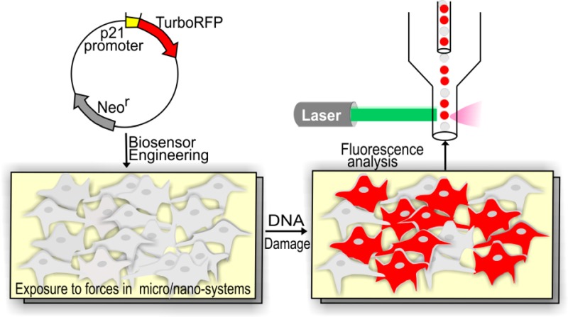
Understanding how newly engineered micro- and nanoscale materials and systems that interact with cells impact cell physiology is crucial for the development and ultimate adoption of such technologies. Reports regarding the genotoxic impact of forces applied to cells in such systems that can both directly or indirectly damage DNA emphasize the need for developing facile methods to assess how materials and technologies affect cell physiology. To address this need we have developed a TurboRFP-based DNA damage reporter cell line in NIH-3T3 cells that fluoresce to report genotoxic stress caused by a wide variety of agents, from chemical genotoxic agents to UV-C radiation. Our biosensor was successfully implemented in reporting the genotoxic impact of nanomaterials, demonstrating the ability to assess size dependent geno- and cyto-toxicity. The biosensor cells can be assayed in a high throughput, noninvasive manner, with no need for overly sophisticated equipment or additional reagents. We believe that this open-source biosensor is an important resource for the community of micro- and nanomaterials and systems designers and users who wish to evaluate the impact of systems and materials on cell physiology.
The use of micro- and nanoscale technologies for biological and medical applications has rapidly advanced in recent years. These technologies have been applied in techniques and platforms for toxicology assessment,1,2 organ-on-a-chip devices for tissue-engineering,3−5 biomedical microelectromechanical systems (Bio-MEMS) for microscale cell manipulation and assessment,6−8 and nanomaterial-based drug delivery systems.9,10 Such approaches offer low-cost and/or new functionality for biological, chemical, pharmaceutical, and environmental applications. Critical in the development of newly engineered micro- and nanoscale materials and systems that interact with cells is the understanding how they impact cell physiology. The geometry and chemistry of nanomaterials and the forces applied on cells in microsystems can both affect cell physiology. Reports regarding the cytotoxic impact of techniques and materials in wide use today2,11−14 emphasize the importance of developing facile methods to assess how materials and technologies affect cell physiology. DNA damage in particular can occur via a variety of mechanisms that are relevant to micro- and nanosystems. Forces applied to cells in such systems can both directly or indirectly damage DNA via reactive oxygen species (ROS).11,15−21 Exposure of cells to light of varying wavelengths,21 heat,22 electric fields,19 and magnetic fields23 has been linked to direct or indirect DNA damage. ROS-induced DNA damage can be caused by a variety of nanomaterials used for biomedical applications,2,12−14,24,25 including commercially available silver nanoparticles (Ag-NPs),14,26 which have a number of therapeutic uses.27
One important concern when developing microsystems and nanomaterials for biomedical applications is with sublethal genotoxic effects. Some of these effects can disrupt DNA integrity without leading to overt cell death and therefore can remain elusive when examining viability. To assay such sublethal genotoxicity, one would ideally want a nondestructive, quantitative, high-throughput assay that is also reagent-free, in order to simplify the assay and limit the interactions of tested microsystems and nanomaterials with any added reagents. Such an assay would allow the biomedical technology designer or user to optimize their newly developed system or material. The genotoxicity assays that are used today include gene expression assays (via RT-PCR),28 single-cell gel electrophoresis assay (comet assay),29 γ-H2AX assay,30 and micronucleus (MN) assay.31 These methods require additional reagents, significant sample preparation, and biological expertise, and they can be difficult to apply to assess nanomaterials and microsystems because these assays may be incompatible with the technology under development (e.g., limited access to cells in a microsystem). Moreover, as the methods are end point, they prevent further assessment of the cells’ recovery and long-term survival.
Methods based instead on engineering cells that fluoresce to report DNA damage have the potential to be reagent-free, simple, and nondestructive. Indeed, development of cell-based toxicity tests is of growing interest, and several genotoxicity-reporting cell-based sensors have become commercially available: the CellSensor beta-lactamase ratiometric fluorescence resonance energy transfer (FRET)-based reporter assay (Invitrogen)32 and the GreenScreen assay (Gentronix Ltd.).33 These assays offer a high-throughput alternative for DNA damage detection. However, the requirements for specialized equipment and software needed for FRET-based measurements, the lack of consensus between different cell biosensor assays on the reporting gene selected or the fluorophore used,32−34 and the costliness of the commercially available sensors emphasize the need to expand the toolbox of available genotoxicity monitoring techniques for use by the nano- and microsystems community for evaluation and optimization of their newly developed systems and materials. The use of the green fluorescent protein (GFP) as a reporting fluorophore for the aforementioned commercial assay further introduces constraints limiting multiple fluorescent labeling, since GFP emission shows a substantial overlap with other fluorophores.
Here we introduce an open-source cell-based biosensor specifically engineered to report DNA damage induced by micro- and nanosystems. The biosensor cells express TurboRFP (red fluorescent protein) fluorescence allowing visual and nondestructive assessment of gene expression with single-cell resolution using commonly available equipment to quantify the cellular fluorescence response without requiring additional reagents and materials, large numbers of cells, or overly sophisticated microscopy. We have developed a transcriptional sensor that reports on activation of p21 protein (cyclin-dependent kinase inhibitor), a crucial node in the DNA damage pathway. We describe the quantitative characterization of the biosensor as well as its application to detect stresses caused by nanomaterials or found in microsystems, specifically Ag-NPs and ROS. The DNA-damage-reporting biosensor presented here offers new possibilities for user-friendly and cost-efficient assessment of DNA damage in a variety of nano- and microsystems.
Materials and Methods
Cell Culture
NIH-3T3 cells, obtained from ATCC, were cultured in Dulbecco’s Modified Eagle’s Medium (DMEM) supplemented with 10% (v/v) bovine calf serum (Hyclone), 2% (v/v) l-glutamine, and 1% (v/v) penicillin-streptomycin. All cell culture reagents were from Invitrogen unless otherwise noted. Cells were grown at 37 °C in a humidified incubator with 5% CO2. For experiments, cells were plated to reach 70% confluence.
Engineering the DNA Damage Cell-Based Biosensor
We engineered a reporter gene construct encoding the fluorescent TurboRFP protein, the expression of which is under the control of the p53-responsive p21 promoter (refer to the Supporting Information, Methods for a detailed summary of the procedure and the sequence of the p53-responsive p21 promoter region). This plasmid was deposited to Addgene (the plasmid number is 52432). The NIH-3T3 cells were transfected using Superfect (Qiagen), selected using selection medium containing 1 mg/mL genetecin (G418) for stably transfected clones, and single-cell cloned (see the Supporting Information, Methods for a more detailed procedure). The isogenic clones were expanded and then assayed to find the clone with the highest fluorescent response to DNA damage.
Quantitative Characterization of the Biosensor Using DNA-Damaging Agents
DNA damage was induced with well-characterized DNA-damaging agents: methylmethanesulfonate (MMS; Sigma-Aldrich) and UV-C (254 nm) by using a Spectrolinker XL-1500 UV cross-linker (Spectronics Corporation). MMS was diluted in cell culture medium not supplemented with bovine calf serum immediately before use at concentrations of 0.05–1.5 mM. Cells were incubated in cell culture medium with MMS for 4 h, then washed with PBS, and incubated in normal cell culture medium until further analysis. The control cells were exposed to the same medium without MMS and to the same number of washes. Cellular response to UV induced DNA damage was assessed using doses of 8, 20, and 35 J/m2. Biosensor cells were washed with PBS prior to the UV exposure and after the exposure incubated in normal cell culture medium until further analysis. The control cells were placed outside the incubator for the same amount of time as UV-exposed biosensor cells and were washed the same number of times with PBS. The red fluorescence response of the biosensor cells was determined at different time points after exposure using flow cytometry (FC).
Pathway Validation
To assess the dependence of TurboRFP expression on p53-pathway activation, the biosensor cells were transfected with p53 shRNA (small hairpin RNA) plasmid (Addgene plasmid 12090) directed against mouse p53.35 Enhanced-GFP (EGFP) is expressed from this plasmid as a marker. EGFP-positive cells were isolated after 6 days using a MoFlo flow sorter and expanded for 7 days before MMS induction. Cells were exposed to MMS for 4 h and analyzed after 24 h.
Cell Viability
Cell viability following exposure to different MMS concentrations was assessed by staining cells (including the cells in supernatant) with 1 μM Sytox-Blue (Invitrogen) for 5–30 min and analyzing them using FC. The percentage of dead cells was determined by Sytox-Blue positive cells. The fold-induction of red fluorescence was determined from the Sytox-Blue-negative cell population.
Comet Assay
Biosensor cells were treated with MMS diluted in cell culture medium not supplemented with bovine calf serum at concentrations of 0.05–1.5 mM. The control cells were exposed to the same medium without MMS and to the same number of washes. The comet assay was done as previously described36 (see the Supporting Information, Methods for a more detailed procedure).
Treatment of the DNA Damage Biosensor with Ag-NPs
Spherical Ag-NPs (10 nm, 100 nm) were purchased from nanoComposix as 1 000 mg/L in a 2 mM sodium citrate buffer (BioPure aqueous suspensions) and were stored in the dark at 4 °C. Dilutions were created by mixing with cell culture medium. Biosensor cells were exposed to 1–100 μg/mL of silver nanoparticles for 12–48 h, trypsinized, and analyzed using FC. Control biosensor cells were exposed to cell culture medium with sodium citrate buffer.
Quantitative Characterization of the Sensor in Response to H2O2 Exposure
The DNA damage biosensor cells were exposed to the culture medium containing the indicated concentration of H2O2 (25–500 μM), with or without catalase (100 mg/mL; Sigma-Aldrich), for 4 h, at which time cells where washed and incubated in normal cell culture medium until further analysis. The response of biosensor cells to H2O2 was compared to the response of cells pretreated with catalase (100 mg/mL; Sigma-Aldrich) for 2 h prior to adding H2O2.
Imaging
Images were acquired with an Axiovert 200 M microscope (Zeiss) fitted with a cooled CCD camera LaVision ImagerQE (LaVision) and an automated stage Ludl MAC 5000 (Ludl) using 10× and 20× objectives. Metamorph software (Molecular Devices) was used to control the microscope. Fluorescent images were acquired using a TRITC filter (for TurboRFP) and FITC filter for EGFP. Images were analyzed using ImageJ.
Flow Cytometry Analysis
The biosensor cells were trypsinized (Gibco), diluted in FACS buffer (95% (v/v) PBS, 5% (v/v) BCS, 1% (v/v) penicillin-streptomycin), and transported on ice to the Swanson Biotechnology Center Flow Cytometry Facility (Koch Institute, MIT). The red fluorescence response of the DNA damage reporter cells was analyzed by an LSR II HTS flow cytometer (BD Biosciences) using a PETexasRed-YG-A (Red channel) filter (561 nm excitation and 610 ± 20 nm emission). The FITC channel (488 nm excitation and 530 ± 30 nm emission wavelengths) was used either as a reference channel or for green fluorescence (EGFP) detection. Side scatter (SSC) and forward scatter (FSC) gates were set to exclude debris. Untransfected NIH-3T3 cells and stable RFP-expressing cells were used as controls. A minimum of 1500 events was collected per sample. The maximum background fluorescence from the untransfected NIH-3T3 cells was set as the threshold and the cells with the red fluorescent values above this threshold were termed “activated cells”. To obtain the fold-induction of the red fluorescence of biosensor cells in response to DNA damage, the mean red fluorescence of the cells exposed to a DNA damaging agent was divided by the mean red florescence of the control (not exposed to genotoxic agent) population of biosensor cells. Flow cytometry data was collected and analyzed using FACSDiva (San Jose, California) and FlowJo (Ashland, OR) software.
Statistical Analysis
The statistical significance of the differences between fold-inductions of mean red fluorescence was conducted using two-tailed Student’s t test, considering p < 0.05 as significant and one-way ANOVA and Dunnett’s test with P < 0.05 (GraphPad Prism 5 software) to compare the fold-induction of red fluorescence caused by different concentrations of the stressors to the fold-induction of the control cells at each time point. The control biosensor cells were exposed to the same conditions as the stressed biosensor cells, except the stressor agent itself and were compared to the untreated biosensor cells to measure their red fluorescence fold-induction. For all analysis: ∗ = p-value < 0.05.
Results
Selection of the DNA Damage-Reporting Cell-Based Biosensor
Cells respond to DNA damage by halting cell cycle progression, which leads to p53-mediated cell cycle arrest37 in order to enable the cell to perform DNA repair processes. Genes that are activated in response to DNA damaging stress have been extensively studied and characterized;37−39 they include the canonical p53 pathway. The major downstream target gene of active p53 transcription factor is p21 (cyclin-dependent kinase inhibitor),40,41 which inhibits both the transition from G1 to S and from G2 to mitosis,41,42 as well as DNA replication.43 Elevation of p21 expression in response to DNA damage has been previously found both in vivo and in vitro.44−46 Hence, our approach for creating a biosensor to report on DNA damage was to construct a cell-cycle arrest sensor by fusing the p53-responsive p21 promoter with the fluorescent reporter protein TurboRFP, similar to an approach previously implemented in our lab to develop a cell-based biosensor to report on heat shock pathway activation.47
We chose to create the sensor in the NIH-3T3 cell line as it is a commonly used fibroblast cell line that is simple to culture, the DNA damage response has been extensively studied in these cells, and they express wild-type p53 protein.48,49 We created a plasmid containing the full-length (667 base-pairs) p21 promoter upstream of TurboRFP (Figure S1 in the Supporting Information). Upon stable transfection we single-cell cloned the mixed population of cells to achieve a clonal population. Clones that stably incorporate foreign DNA can demonstrate a wide variation in recombinant gene expression. The reason for this can be the positional effects, in which different regions of the chromosome modulate transgene expression. In order to minimize this heterogeneity and to achieve more consistent performance we used an approach that was previously used for cell-based toxicity assay development, namely, selecting the highest producing clone.34,47 We examined the clones for RFP induction and for the percentage of positive cells, setting the threshold for determining positive cells from the brightest autofluorescence signal from untransfected NIH-3T3 cells. The screening of the clones for RFP induction was performed using flow cytometry after exposure of the cells to methylmethanesulfonate (MMS) as a genotoxic agent. MMS is a DNA alkylating agent that causes random single- and double-strand DNA breaks. It is a well-characterized DNA damaging agent that induces the transitory delay of DNA replication. Its ease of use and its rapid uptake by cells made it a reagent of choice for selection and characterization of the DNA-damage reporter clone. Cells were exposed to MMS (1 mM) for 4 h and analyzed 24 h later using FC.
We screened 50 clones (Figure S2 in the Supporting Information). As expected, each clone had different characteristics regarding the expression of red fluorescent protein before and after induction (Figure S2 in the Supporting Information). We compared different clones according to the fold-induction of the mean red fluorescence and the percentage of positive cells.
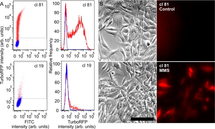
Examining two clones in detail (clone 81, clone 19) gives insight into the different responses observed (Figure 1A). The control populations of these clones differ in % positive and in mean intensity: clone 19 had 2.85% positive cells with mean fluorescence of the entire control population of 60.8 (arbitrary units), whereas clone 81 cells that had only 0.029% positive red cells with a mean red fluorescence of 38.5 (arbitrary units) 24 h after exposure to MMS (1 mM). Clone 81 cells showed a substantial population shift (Figure 1A), with 74.5% cells expressing RFP (mean fluorescence 3331, 86.5 times higher than the control), compared to clone 19 with only 16.6% red cells after induction with mean fluorescence intensity of 191 (Figure 1A), only 3 times higher than the mean fluorescence intensity of the control population. After analyzing all 50 clones, we found that clone 81 displayed both the highest fold-induction of the mean red fluorescence and the highest percentage of red cells. Because of both the low red fluorescence signal of the control unstressed cells and the high induction of the RFP after exposure to genotoxic agent, as compared to other clones, clone 81 was selected as our biosensor. Additionally, to demonstrate that the selected biosensor cells are amenable to assessment by microscopy, imaging before and after DNA damage induction showed visible activation of the reporter (Figure 1B).
Figure 1.
(A) Left panel, FC scatter plots of TurboRFP intensity (y axis; arbitrary units) in response to MMS (1 mM) of two clones, 81 and 19 (blue-control unstressed cells; red-cells exposed to MMS); right panel, RFP intensity distribution histogram for clones 81 and 19 after exposure to MMS (red) compared to control (blue). (B) Phase (left) and fluorescence (right) images of clone 81 cells before and after 1 mM MMS exposure for 4 h. Images were taken 24 h after the exposure. Stressed cells expressed the red fluorescence, showing visible activation of the reporter. Scale bar 100 μm.
Validation of the Dependence of TurboRFP Expression on p53-Pathway Activation
To assess the specificity of our biosensor, we examined its response upon pathway inhibition. We knocked down p53 by transfecting the sensor with a plasmid containing an EGFP (enhanced GFP) marker and a p53 shRNA (small hairpin RNA) directed against mouse p53. Cells that were EGFP-negative turned red upon MMS induction, whereas EGFP-positive cells were not red (Figure 2A,B). Fold-induction of mean red fluorescence was 16 ± 0.5 in EGFP– cells and was significantly reduced to 5.6 ± 0.3 in - EGFP+ cells (P < 0.05) (Figure 2A,C), indicating that cells that were transfected with p53 shRNA (green) were inhibited in their ability to express TurboRFP. This inhibition demonstrated that p53 is required for RFP expression in our biosensors and thus that the expression of TurboRFP is driven by p53-induced transcription.
Figure 2.
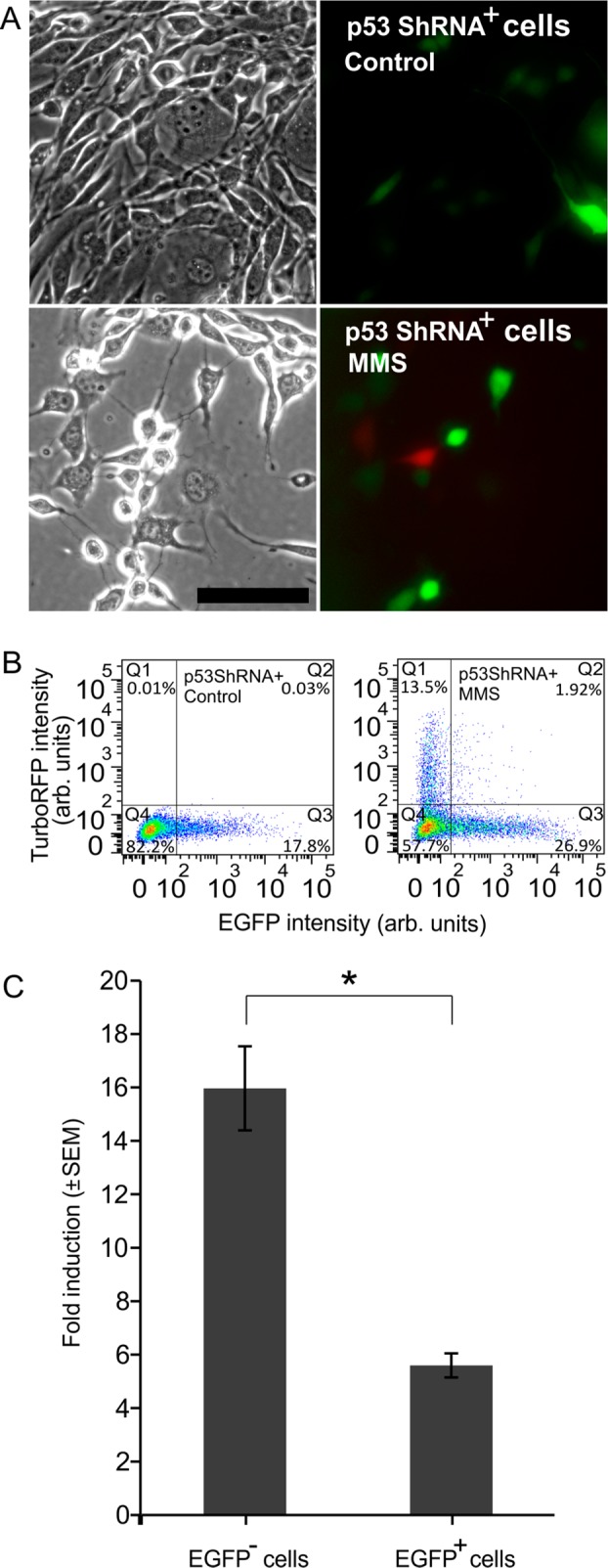
(A) Phase and fluorescence images of p53 shRNA transfected DNA damage biosensor cells expressing EGFP (green) without (controls) and with (MMS) exposure to 1 mM MMS. Scale bar is 100 μm. Cells that express EGFP did not exhibit red fluorescence. (B) FC scatter plots of p53 shRNA transfected biosensors’ TurboRFP signal of controls (left) and exposed to MMS (right). (C) Fold-induction of red fluorescence of p53 shRNA-transfected cells in response to MMS. EGFP– cells are derived from Q1 and Q4 of part B, right scatter plot, and EGFP+ cells are from Q2 and Q3 of part B, right scatter plot.
Response of DNA Damage Biosensors to MMS
We next characterized the dynamics and dose-dependence of the DNA damage biosensor response to MMS. MMS concentrations above 0.65 mM caused significant red fluorescence induction compared to the controls (Figure 3A). Higher MMS concentrations resulted in a graded dose-dependent increase in fold-induction of TurboRFP levels, reaching the highest response using an MMS concentration of 1 mM. Above this concentration, cells displayed no additional increases in fold-induction of red fluorescence signal, reaching a plateau. At concentrations of 1.2 mM and above, fold TurboRFP induction decreased, consistent with the observation that at these concentrations the percentage of dead cells started to increase above the baseline (Figure S3A in the Supporting Information), indicating the onset of MMS cytotoxicity. Since dead cells tend to be lost during sample processing for FC, the fluorescence decrease in Figure 3A likely occurred due to the loss of the brightest (and thus most damaged) cells as they die. Correlation of fold-induction obtained 24 h after exposure with single-cell comet assay36 (Figure S3B,C in the Supporting Information) at MMS concentrations of 0.05–1 mM confirmed a monotonic relationship between DNA damage and fold-induction of red fluorescence, showing a linear relationship between the red fold-induction and DNA damage measured by comet assay starting from 36% DNA in the tail (R2 = 0.99) (Figure S3C in the Supporting Information).
Figure 3.
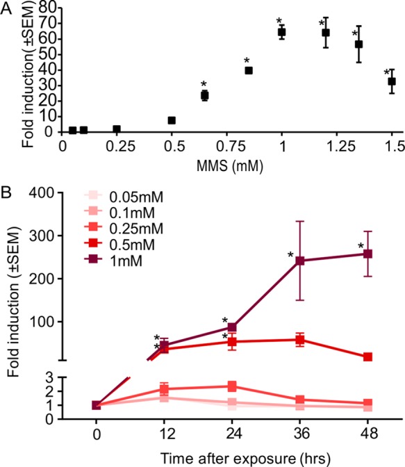
(A) Mean fold-induction of TurboRFP expression in biosensor cells treated with increasing MMS concentrations; analyzed using FC 24 h after 4 h exposure. (B) Time dependence of fold-induction of TurboRFP expression in response to different MMS concentrations (n ≥ 3; error bars, standard error of mean).
Next we examined the dynamics of activation. The rise in TurboRFP fluorescence in response to MMS was time-dependent, as reflected in the increase of the mean red fluorescence fold-induction over time, with different concentrations of MMS exhibiting different dynamics (Figure 3B). After 12 h, the biosensor cells exposed to 0.5 and 1 mM MMS concentrations showed significant increase in expression of TurboRFP. After 24 h, the fluorescence of cells exposed to 0.5 mM MMS plateaued and then decreased after 36 h, suggesting that the cells were recovering from the stress. Fluorescence in cells exposed to 1 mM MMS stayed elevated for at least 48 h.
DNA-Damage Biosensors’ Response to UV Radiation
To assay the response of the biosensor to other common DNA damaging agents, we exposed it to UV-C radiation. Using radiation allowed us to induce DNA damage free from limitations of chemical uptake and metabolism.50 UV-C is a well-characterized genotoxic agent that is used to study DNA damage and repair.51 Recently it has become relevant in various medical applications, including acting as an anticancer agent52 and as a disinfectant for localized treatments of multidrug-resistant infections.53 Cells exposed to 20 J/m2 and 35 J/m2 doses of UV-C showed a significant increase in fluorescence after 12 h (Figure 4). Biosensor cells’ response to 20 J/m2 and 35 J/m2 UV-C showed further induction after 24 h, with higher levels of fold-induction in response to 35 J/m2. This response stayed relatively constant for up to 48 h.
Figure 4.
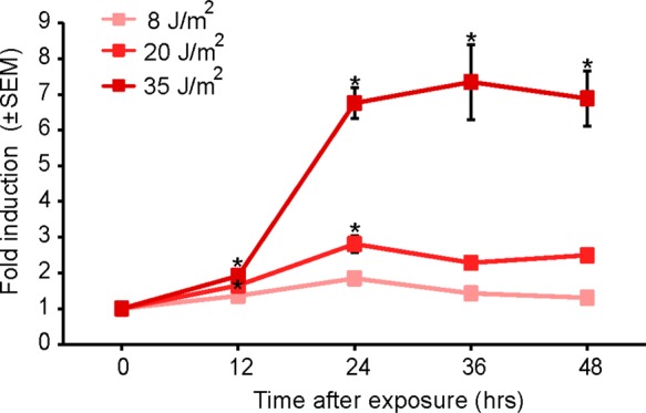
Dose and time response of DNA-damage biosensor cells to UV-C. Exposed cells were analyzed using FC at different time points after exposure, and the mean red fluorescence intensity was compared to the mean red fluorescence intensity of the control biosensor cells (n = 3; error bars, standard error of mean).
DNA-Damage Biosensors’ Response to Silver Nanoparticles (Ag-NPs)
To demonstrate the use of the biosensor in a nanotechnological application, we implemented it to assay genotoxicity of Ag-NPs. Ag-NPs are widely used in biomedical research and for therapeutic purposes due to their electrical conductivity54 and antimicrobial properties.27 Recent reports about the genotoxic potential of this nanomaterial has sparked significant interest in this aspect of Ag-NPs’ impact on cell physiology.14,26 Here a benefit of the biosensor is the simplicity of assay: simply add the Ag-NPs into a microtiter plate containing the cells and then read on a flow cytometer, allowing assay of many conditions (particle types, concentrations, and durations). Exposure of biosensor cells to Ag-NPs and analysis of their red fluorescence induction using FC showed a significant response to 10 and 100 nm Ag-NPs at concentrations of 50 and 100 μg/mL starting at 12 h of exposure (Figure 5). After 24 h of exposure to 10 μg/mL of 10 nm Ag-NPs, biosensor cells exhibited a significant fold-induction of red fluorescence, similar to the response of 100 μg/mL of the 100 nm Ag-NPs, suggesting that the 10 nm nanoparticles were more genotoxic than the 100 nm nanoparticles. Lower concentration of 10 nm NPs resulted in no significant fluorescence induction. For the 100 nm NPs after 48 h of exposure, 50 μg/mL caused significant TurboRFP induction, as high as that caused by 10 μg/mL of the 10 nm Ag-NPs. Exposure of cells to 100 μg/mL of the 100 nm Ag-NPs after 48 h resulted in a decrease in mean fold-induction of red fluorescence, probably due to the decrease in cell viability caused by the long exposure (Figure S4 in the Supporting Information). For the 10 nm Ag-NPs, meanwhile, concentrations of 50 and 100 μg/mL resulted in significant cell loss (Figure S4 in the Supporting Information). The apparent increased toxicity of the smaller Ag-NPs is in agreement with published reports assaying the size-dependent toxicity of Ag-NPs.55,56
Figure 5.
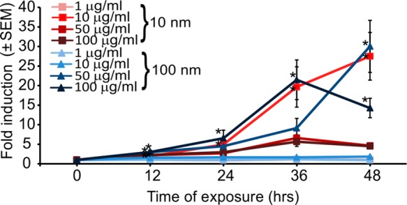
Dose and time response of DNA-damage reporter cells to Ag-NPs. Exposed cells were analyzed using FC at different time points after exposure and the mean red fluorescence intensity was compared to the mean red fluorescence intensity of the control biosensor cells (n = 3; error bars, standard error of mean).
DNA-Damage Biosensors’ Response to Oxidative Stress
Oxidative stress is a common adverse outcome caused by various forces and materials used or generated in micro- and nanosystems, such as electric fields,57 heat,47 and various nanoparticles,2,13,14,24 which perturbs the balance between intracellular formation and degradation of ROS. Reflecting the importance of ROS as a stress agent, we characterized the response of the biosensor to ROS. Addition of exogenous H2O2 mimics cellular oxidative stress because of the permeability of cell membranes to this small molecule. Sensors exposed to different concentrations of hydrogen peroxide showed time- and dose-dependent induction of fluorescence (Figure 6). Significant induction of TurboRFP expression was observed for H2O2 concentrations ≥100 μM 12 h after exposure. Fluorescence of cells exposed to 500 μM H2O2 plateaued after 24 h at a level of fold-induction similar to that reached by cells exposed to 300 μM H2O2 after 48 h. To determine the specificity of the response to ROS, we pretreated biosensor cells with catalase, a ROS scavenger enzyme. Pretreatment abrogated induction of TurboRFP expression in response to H2O2 at all concentrations and times assayed, demonstrating the specificity of the damage mechanism.
Figure 6.
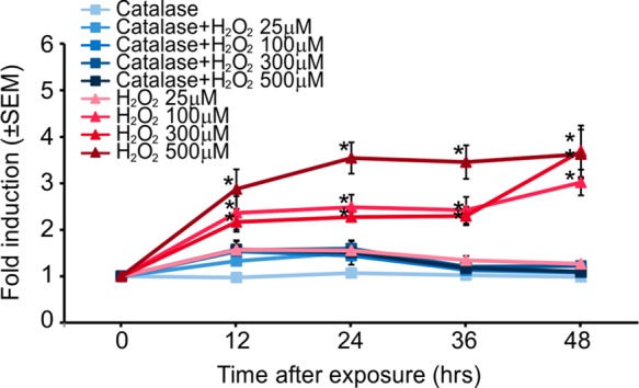
Dose and time response of DNA-damage biosensor cells to H2O2 analyzed using FC. Pretreatment of the biosensor cells with ROS scavenger enzyme catalase (100 mg/mL) resulted in an attenuation of the biosensor activation (n = 3; error bars, standard error of mean).
Discussion
Understanding how newly engineered micro- and nanoscale materials and systems, meant to interact with cells, impact the physiology of those cells is critical when developing such systems and for their ultimate adoption. Reports regarding the cytotoxic impact of micro- and nanoscale techniques and materials that are in wide use today for biological and medical applications2,11−14,58 emphasize the importance of developing facile methods to assess this impact on cell physiology. Viability is important and straightforward to assess but does not report on sublethal stresses. Cell morphology and growth can report on sublethal stresses, but their limited specificity precludes identification of the causes of any observed changes in morphology or growth.
Gene expression28 (via RT-PCR), comet assay,29 γ-H2AX assay,30 and micronucleus (MN) assay31 are common ways to assess sublethal DNA damage but can be difficult to apply to micro- and nanoscale materials and systems because the assays may be incompatible with the technology under development (e.g., limited access to cells in a microsystem).
Fluorescence reporter assays using stable reporter cell lines have several appealing features for these applications. First, they are easy to implement, only requiring a flow cytometer or a microscope. They are nondestructive to the cells and are thus compatible with downstream assays (such as a viability assay, Figure S3A in the Supporting Information). They are typically reagent-free, and so work with materials and systems with reagent addition is difficult. All these features lead to throughputs compatible with testing across different conditions. Indeed several cell-based sensors have been developed to assess DNA damage.32−34,59 Each is different either in the gene whose activation they report on33 or in the reporter fluorophore used.32−34 However, the commercially available cell-based assays, such as CellSensor (Invitrogen) and GreenScreen assay (Gentronix) are expensive, $10 000 for a vial and $5 000 for a kit, respectively. In addition, these assays have not been evaluated across different types of genotoxic stressors. Also when the GreenScreen assay (yeast background cells) was used to evaluate various engineered nanomaterials, no measurable genotoxicity was shown for different genotoxic nanoparticles, including 10 nm Ag-NPs, in contrast to the sensor reported here (Figure 5).60
Here we introduced an open-source biosensor specifically engineered to report on DNA damage induced by micro- and nanosystems. This transcriptional sensor reports on activation of p21, a crucial and well-characterized node in the DNA damage and cell cycle arrest pathway, via p53-driven TurboRFP protein expression. The biosensor allows visual and nondestructive assessment of gene expression with single-cell resolution using commonly available equipment to quantify the cellular fluorescence response without requiring additional reagents and materials, large numbers of cells, or overly sophisticated microscopy. We engineered the biosensor cells to use TurboRFP because of its intracellular stability, which allows RFP to be assayed over a range of times and because its spectral characteristics allows it to be more-easily multiplexed with other assays than a GFP-based reporter. We chose NIH-3T3 cells as the background because they are one of the most commonly used fibroblast cell lines, are very easy to culture, express wild type p53 protein, and have been extensively studied for DNA damage,48,49 showing sensitivity to different types of genotoxic agents. We have also deposited the reporter plasmid in Addgene for users wishing to create the sensor in different background cells to get specific stress responses, while our biosensor is available from us upon request. After validating that expression of TurboRFP was dependent on the p53 availability, we characterized our biosensor using agents with known genotoxic function. The biosensor cells were exposed to a range of concentrations, from very low concentration that did not induce significant fluorescence responses up to concentrations that were cytotoxic and caused cell death, in order to determine the dynamics of the dose- and time-response. Most genotoxic agents at high enough concentration induced a significant response of the biosensor 12 h after exposure, including MMS, UV-C, hydrogen peroxide, and Ag-NPs, but at this time point it was not always possible to distinguish between responses to different doses or concentrations. At exposure times of ≥24 h it was possible to detect the fold-induction of red fluorescence caused by lower but nevertheless genotoxic concentrations of the stressors. Thus, it is likely that for most applications read-out at ∼24 h following exposure will be optimal. This read-out time is similar to those of commercially available cell-based assays, which also range between 24 and 48 h. The sensitivity of our biosensor for MMS genotoxicity detection is similar to that of the GreenScreen assay.33
To illustrate use cases for both nanomaterials and microsystems, we exposed biosensor cells to Ag-NPs and to hydrogen peroxide (a common stressor found in microsystems). The biosensor cells responded to the stressors in ways consistent with published observations55,56 (e.g., the difference in apparent toxicity between 10 and 100 nm diameter Ag-NPs, reporting higher toxicity for smaller nanoparticles). These assays also illustrate how designers might interpret the results of assays; they provide a relative measure of genotoxicity rather than an absolute one. In practice, then, we envision users comparing fold-induction across conditions/systems and picking the condition/system with the minimal fold-induction, rather than use the fold-induction as an absolute metric of genotoxicity.
Conclusion
We have develop a TurboRFP-based DNA damage reporter cell line in NIH-3T3 cells that showed the ability to report genotoxic stress caused by wide variety of agents, from chemical genotoxic agents to UV-C radiation. In addition, the biosensors were successfully implemented in reporting the genotoxic impact of nanomaterials, demonstrating the ability to assess size dependent geno- and cyto-toxicity. The biosensor cells can be assayed in a high-throughput, noninvasive manner, with no need for sophisticated equipment or reagents. This open-source biosensor now serves as an important resource for the community of micro- and nanosystems and materials designers and users who wish to evaluate the impact of the systems and materials on cell physiology.
Acknowledgments
This work was supported by the NIH (Grant GM090194). We thank the staff of The Swanson Biotechnology Center Flow Cytometry Facility at MIT for their technical advice regarding flow cytometry. We thank Prof. B. P. Engelward for providing the platform to run the comet assay and Y. Su and J. Ge for their assistance, training, and discussions. We thank Joseph D. Steinmeyer for insightful discussions and help.
Supporting Information Available
Detailed methods as noted in the text and supplementary figures. This material is available free of charge via the Internet at http://pubs.acs.org.
Author Contributions
J.V. and A.F. designed the experiments. A.F., C.T.L., and S.V. performed the experiments. J.V. and A.F. wrote the manuscript. All authors edited the manuscript and have given approval to the final version of the manuscript.
The authors declare no competing financial interest.
Funding Statement
National Institutes of Health, United States
Supplementary Material
References
- Toh Y. C.; Zhang C.; Zhang J.; Khong Y. M.; Chang S.; Samper V. D.; van Noort D.; Hutmacher D. W.; Yu H. Lab Chip 2007, 7, 302–309. [DOI] [PubMed] [Google Scholar]
- Bhabra G.; Sood A.; Fisher B.; Cartwright L.; Saunders M.; Evans W. H.; Surprenant A.; Lopez-Castejon G.; Mann S.; Davis S. A.; Hails L. A.; Ingham E.; Verkade P.; Lane J.; Heesom K.; Newson R.; Case C. P. Nat. Nanotechnol. 2009, 4, 876–883. [DOI] [PubMed] [Google Scholar]
- Hung P. J.; Lee P. J.; Sabounchi P.; Lin R.; Lee L. P. Biotechnol. Bioeng. 2005, 89, 1–8. [DOI] [PubMed] [Google Scholar]
- Huh D.; Matthews B. D.; Mammoto A.; Montoya-Zavala M.; Hsin H. Y.; Ingber D. E. Science 2010, 328, 1662–1668. [DOI] [PMC free article] [PubMed] [Google Scholar]
- Grosberg A.; Alford P. W.; McCain M. L.; Parker K. K. Lab Chip 2011, 11, 4165–4173. [DOI] [PMC free article] [PubMed] [Google Scholar]
- Taff B. M.; Voldman J. Anal. Chem. 2005, 77, 7976–7983. [DOI] [PubMed] [Google Scholar]
- Fendyur A.; Mazurski N.; Shappir J.; Spira M. E. Front. Neuroeng. 2011, 4, 14. [DOI] [PMC free article] [PubMed] [Google Scholar]
- Honegger T.; Scott M. A.; Yanik M. F.; Voldman J. Lab Chip 2013, 13, 589–598. [DOI] [PMC free article] [PubMed] [Google Scholar]
- Cheng R.; Meng F.; Deng C.; Klok H. A.; Zhong Z. Biomaterials 2013, 34, 3647–3657. [DOI] [PubMed] [Google Scholar]
- Demirel G. B.; von Klitzing R. ChemPhysChem 2013, 14, 2833–2840. [DOI] [PubMed] [Google Scholar]
- Lopacinska J. M.; Emneus J.; Dufva M. PLoS One 2013, 8, e53107. [DOI] [PMC free article] [PubMed] [Google Scholar]
- Chen Y.; Qu K.; Zhao C.; Wu L.; Ren J.; Wang J.; Qu X. Nat. Commun. 2012, 3, 1074. [DOI] [PubMed] [Google Scholar]
- Papageorgiou I.; Brown C.; Schins R.; Singh S.; Newson R.; Davis S.; Fisher J.; Ingham E.; Case C. P. Biomaterials 2007, 28, 2946–2958. [DOI] [PubMed] [Google Scholar]
- AshaRani P. V.; Low Kah Mun G.; Hande M. P.; Valiyaveettil S. ACS Nano 2009, 3, 279–290. [DOI] [PubMed] [Google Scholar]
- Zhang X.; Rosenstein B. S.; Wang Y.; Lebwohl M.; Wei H. Free Radical Biol. Med. 1997, 23, 980–985. [DOI] [PubMed] [Google Scholar]
- Willers H.; Dahm-Daphi J.; Powell S. N. Br. J. Cancer 2004, 90, 1297–1301. [DOI] [PMC free article] [PubMed] [Google Scholar]
- Bertram C.; Hass R. Biol. Chem. 2008, 389, 211–220. [DOI] [PubMed] [Google Scholar]
- Kultz D. Annu. Rev. Physiol. 2005, 67, 225–257. [DOI] [PubMed] [Google Scholar]
- Au S. H.; Fobel R.; Desai S. P.; Voldman J.; Wheeler A. R. Integr. Biol. 2013, 5, 1014–1025. [DOI] [PubMed] [Google Scholar]
- Ruiz-Gomez M. J.; Martinez-Morillo M. Electromagn. Biol. Med. 2009, 28, 201–214. [DOI] [PubMed] [Google Scholar]
- Ge J.; Wood D. K.; Weingeist D. M.; Prasongtanakij S.; Navasumrit P.; Ruchirawat M.; Engelward B. P. Cytometry, Part A 2013, 83, 552–560. [DOI] [PMC free article] [PubMed] [Google Scholar]
- Purschke M.; Laubach H. J.; Anderson R. R.; Manstein D. J. Invest. Dermatol. 2010, 130, 86–92. [DOI] [PubMed] [Google Scholar]
- Lai H.; Singh N. P. Environ. Health Perspect. 2004, 112, 687–694. [DOI] [PMC free article] [PubMed] [Google Scholar]
- Guichard Y.; Schmit J.; Darne C.; Gate L.; Goutet M.; Rousset D.; Rastoix O.; Wrobel R.; Witschger O.; Martin A.; Fierro V.; Binet S. Ann. Occup. Hyg. 2012, 56, 631–644. [DOI] [PubMed] [Google Scholar]
- Mu Q.; Hondow N. S.; Krzeminski L.; Brown A. P.; Jeuken L. J.; Routledge M. N. Part. Fibre Toxicol. 2012, 9, 29. [DOI] [PMC free article] [PubMed] [Google Scholar]
- Kim H. R.; Park Y. J.; Shin D. Y.; Oh S. M.; Chung K. H. Environ. Health Toxicol. 2013, 28, e2013003. [DOI] [PMC free article] [PubMed] [Google Scholar]
- Chen X.; Schluesener H. J. Toxicol. Lett. 2008, 176, 1–12. [DOI] [PubMed] [Google Scholar]
- Ellinger-Ziegelbauer H.; Fostel J. M.; Aruga C.; Bauer D.; Boitier E.; Deng S.; Dickinson D.; Le Fevre A. C.; Fornace A. J. Jr.; Grenet O.; Gu Y.; Hoflack J. C.; Shiiyama M.; Smith R.; Snyder R. D.; Spire C.; Tanaka G.; Aubrecht J. Toxicol. Sci. 2009, 110, 341–352. [DOI] [PMC free article] [PubMed] [Google Scholar]
- Azqueta A.; Collins A. R. Arch. Toxicol. 2013, 87, 949–968. [DOI] [PubMed] [Google Scholar]
- Kuo L. J.; Yang L. X. In Vivo 2008, 22, 305–309. [PubMed] [Google Scholar]
- Samanta S.; Dey P. Diagn. Cytopathol. 2012, 40, 84–90. [DOI] [PubMed] [Google Scholar]
- Smith A. J.; Hancock M. K.; Bi K.; Andrews J.; Harrison P.; Vaughan T. J. J. Biomol. Screen. 2012, 17, 713–726. [DOI] [PubMed] [Google Scholar]
- Hastwell P. W.; Chai L. L.; Roberts K. J.; Webster T. W.; Harvey J. S.; Rees R. W.; Walmsley R. M. Mutat. Res. 2006, 607, 160–175. [DOI] [PubMed] [Google Scholar]
- Zager V.; Cemazar M.; Hreljac I.; Lah T. T.; Sersa G.; Filipic M. Radiol. Oncol. 2010, 44, 42–51. [DOI] [PMC free article] [PubMed] [Google Scholar]
- Ventura A.; Meissner A.; Dillon C. P.; McManus M.; Sharp P. A.; Van Parijs L.; Jaenisch R.; Jacks T. Proc. Natl. Acad. Sci. U.S.A. 2004, 101, 10380–10385. [DOI] [PMC free article] [PubMed] [Google Scholar]
- Wood D. K.; Weingeist D. M.; Bhatia S. N.; Engelward B. P. Proc. Natl. Acad. Sci. U.S.A. 2010, 107, 10008–10013. [DOI] [PMC free article] [PubMed] [Google Scholar]
- Zhou B. B.; Elledge S. J. Nature 2000, 408, 433–439. [DOI] [PubMed] [Google Scholar]
- Levine A. J.; Hu W.; Feng Z. Cell Death Differ. 2006, 13, 1027–1036. [DOI] [PubMed] [Google Scholar]
- Harris S. L.; Levine A. J. Oncogene 2005, 24, 2899–2908. [DOI] [PubMed] [Google Scholar]
- Waldman T.; Kinzler K. W.; Vogelstein B. Cancer Res. 1995, 55, 5187–5190. [PubMed] [Google Scholar]
- Vogelstein B.; Lane D.; Levine A. J. Nature 2000, 408, 307–310. [DOI] [PubMed] [Google Scholar]
- Bunz F.; Dutriaux A.; Lengauer C.; Waldman T.; Zhou S.; Brown J. P.; Sedivy J. M.; Kinzler K. W.; Vogelstein B. Science 1998, 282, 1497–1501. [DOI] [PubMed] [Google Scholar]
- Moldovan G. L.; Pfander B.; Jentsch S. Cell 2007, 129, 665–679. [DOI] [PubMed] [Google Scholar]
- Sitko J. C.; Yeh B.; Kim M.; Zhou H.; Takaesu G.; Yoshimura A.; McBride W. H.; Jewett A.; Jamieson C. A.; Cacalano N. A. Cell. Signal. 2008, 20, 2221–2230. [DOI] [PMC free article] [PubMed] [Google Scholar]
- Hattinger C. M.; Jochemsen A. G.; Tanke H. J.; Dirks R. W. J. Histochem. Cytochem. 2002, 50, 81–89. [DOI] [PubMed] [Google Scholar]
- Fei P.; Bernhard E. J.; El-Deiry W. S. Cancer Res. 2002, 62, 7316–7327. [PubMed] [Google Scholar]
- Desai S. P.; Voldman J. Integr. Biol. 2011, 3, 48–56. [DOI] [PMC free article] [PubMed] [Google Scholar]
- Gentiletti F.; Mancini F.; D’Angelo M.; Sacchi A.; Pontecorvi A.; Jochemsen A. G.; Moretti F. Oncogene 2002, 21, 867–877. [DOI] [PubMed] [Google Scholar]
- Dkhissi F.; Raynal S.; Jullien P.; Lawrence D. A. Oncogene 1999, 18, 703–711. [DOI] [PubMed] [Google Scholar]
- Amundson S. A.; Do K. T.; Vinikoor L.; Koch-Paiz C. A.; Bittner M. L.; Trent J. M.; Meltzer P.; Fornace A. J. Jr. Oncogene 2005, 24, 4572–4579. [DOI] [PubMed] [Google Scholar]
- Hall J. R.; Kow E.; Nevis K. R.; Lu C. K.; Luce K. S.; Zhong Q.; Cook J. G. Mol. Biol. Cell 2007, 18, 3340–3350. [DOI] [PMC free article] [PubMed] [Google Scholar]
- Kawaguchi J.; Adachi S.; Yasuda I.; Yamauchi T.; Nakashima M.; Ohno T.; Shimizu M.; Yoshioka T.; Itani M.; Kozawa O.; Moriwaki H. Mol. Cancer 2012, 11, 45. [DOI] [PMC free article] [PubMed] [Google Scholar]
- Dai T.; Vrahas M. S.; Murray C. K.; Hamblin M. R. Expert Rev. Anti-Infect. Ther. 2012, 10, 185–195. [DOI] [PMC free article] [PubMed] [Google Scholar]
- Mannoor M. S.; Jiang Z.; James T.; Kong Y. L.; Malatesta K. A.; Soboyejo W. O.; Verma N.; Gracias D. H.; McAlpine M. C. Nano Lett. 2013, 13, 2634–2639. [DOI] [PMC free article] [PubMed] [Google Scholar]
- Carlson C.; Hussain S. M.; Schrand A. M.; Braydich-Stolle L. K.; Hess K. L.; Jones R. L.; Schlager J. J. J. Phys. Chem. B 2008, 112, 13608–13619. [DOI] [PubMed] [Google Scholar]
- Park J.; Lim D. H.; Lim H. J.; Kwon T.; Choi J. S.; Jeong S.; Choi I. H.; Cheon J. Chem. Commun. (Cambridge, U. K.) 2011, 47, 4382–4384. [DOI] [PubMed] [Google Scholar]
- Wolf-Goldberg T.; Barbul A.; Ben-Dov N.; Korenstein R. Biochim. Biophys. Acta 2013, 1833, 1396–1408. [DOI] [PubMed] [Google Scholar]
- Liu Y.; Zhao Y.; Sun B.; Chen C. Acc. Chem. Res. 2012, 46, 702–713. [DOI] [PubMed] [Google Scholar]
- Knight A. W.; Little S.; Houck K.; Dix D.; Judson R.; Richard A.; McCarroll N.; Akerman G.; Yang C.; Birrell L.; Walmsley R. M. Regul. Toxicol. Pharmacol. 2009, 552188–199. [DOI] [PubMed] [Google Scholar]
- Bayat N.; Rajapakse K.; Marinsek-Logar R.; Drobne D.; Cristobal S. Nanotoxicology 2014, 8, 363–373. [DOI] [PubMed] [Google Scholar]
Associated Data
This section collects any data citations, data availability statements, or supplementary materials included in this article.


