Abstract
Breast reconstruction is an important part of the breast cancer treatment process for many women. Recently, 2D and 3D images have been used by plastic surgeons for evaluating surgical outcomes. Distances between different fiducial points are frequently used as quantitative measures for characterizing breast morphology. Fiducial points can be directly marked on subjects for direct anthropometry, or can be manually marked on images. This paper introduces novel algorithms to automate the identification of fiducial points in 3D images. Automating the process will make measurements of breast morphology more reliable, reducing the inter- and intra-observer bias. Algorithms to identify three fiducial points, the nipples, sternal notch, and umbilicus, are described. The algorithms used for localization of these fiducial points are formulated using a combination of surface curvature and 2D color information. Comparison of the 3D co-ordinates of automatically detected fiducial points and those identified manually, and geodesic distances between the fiducial points are used to validate algorithm performance. The algorithms reliably identified the location of all three of the fiducial points. We dedicate this article to our late colleague and friend, Dr. Elisabeth K. Beahm. Elisabeth was both a talented plastic surgeon and physician-scientist; we deeply miss her insight and her fellowship.
Keywords: 3D surface mesh, breast reconstruction, curvature, breast morphology, landmark detection
Introduction
Accurate measurement of breast morphology is crucial for determining the surgical outcomes of breast reconstruction, and other breast cancer treatments.1,2 Recently, in the fields of aesthetic and reconstructive breast surgery, 3-dimensional (3D) imaging has been validated as a potential tool for obtaining clinical measurements such as surface area and distance, and breast volume.3 Distances between fiducial points are widely used for quantifying breast aesthetic measures such as symmetry4 and ptosis.5 Existing 3D visualization packages provide tools to measure surface path distances, volume, and angles, but annotation of the fiducial points is still done manually, which can introduce inter- and intra-observer variability.3,6 Moreover, a number of the fiducial points are difficult to locate and require a fairly sophisticated understanding of surgical terminology and human anatomy. Thus, automating the process of localizing fiducial points should not only make the measurements of breast aesthetics more accurate and reliable, but also more practical for the busy medical profession.
Detection of 3D fiducial points is critical to a variety of medical applications including magnetic resonance (MR) and X-ray computed tomography (CT) images of the brain in neurology,7 CT images of bones in orthopedics,8 and stereophotogrammetric images in craniofacial surgery.9 3D landmark detection has also been extensively studied in the field of face recognition.10 In both medical11 and computer vision12 applications, a popular approach has been to generate atlases (templates) wherein the atlas is manually generated and landmarks detected on the atlas. For each target image, feature points are detected and matched with those in the atlas to identify the landmarks on the input image. Other approaches for landmark detection have included Point Signatures,13 Spin Image representation,14 and Local Shape Maps.15 Some of these approaches have exhibited high sensitivity to noise. Other practical applications of automated landmark detection on 3D images of the human body are found in the textile industry,16 and in the gaming industry for creation of realistic avatars for virtual reality systems.17 In these studies, however, the focus has been on the identification of anthropometric landmarks such as necklines, bust, waist and hip circumference, torso height, shoulder points, and limb joints. In this study our focus is to identify anatomical landmarks, such as nipples, umbilicus, and sternal notch to facilitate quantification of breast morphology. Our work also contrasts other studies in the ergonomic, textile, and gaming industries in that we need to identify anatomical landmarks that require nude images of the torso. The only other area where identification of landmarks (specifically nipples) in nude images has been attempted is in the field of web image explicit content detection for screening inappropriate adult oriented Internet pages. However, most of this work is performed on 2D photographs.18
To date, our group19 has made all previously published attempts at automated detection of fiducial points for breast morphology assessment from 2D images. Related work on automating quantitative analysis of breast morphology from 2D photographs has also been done by Cardoso et al.20 In this study we present algorithms for the automated identification of three fiducial points—nipples (right (NR) and left (NL)), sternal notch, and umbilicus from 3D torso images.
Materials and Methods
Some of the most effective methods in the field of 3D face recognition for landmark detection rely on estimation of local mean and Gaussian curvature information.21 Our approach combines 3D surface curvature in conjunction with 2D color information for the automated identification of fiducial points. Fiducial points, or landmarks, have unique structural and/or surface properties that differentiate them from their surrounding regions. We reasoned that the key to accurately locating these anatomical fiducial points (nipples, sternal notch, and umbilicus) was to isolate their distinctive morphological features, and to search for them in an appropriate spatially localized region of the torso. Thus the first step was to partition the torso based on the anatomic location of the fiducial point. For example, the central portion of the torso was the region of interest (ROI) for umbilicus identification, whereas the right and left halves of the upper portion of the torso were the ROI’s for the identification of the right and left nipples, respectively. Next, the curvature tensor field was estimated using a toolbox developed by Peyre22 based on the algorithms proposed by Cohen-Steiner et al.23 Using the curvature tensor we determined the principal (kmin and kmax), Gaussian (K), Mean (H), and Shape Index (S), curvature measures.24 In the following sections, we describe in detail the steps employed to automatically detect each of the three fiducial points.
Identification of nipples
For identification of the nipples, the 3D torso image was first partitioned into two halves, left and right for locating NL and NR, respectively. Each ROI was automatically segmented based on a priori knowledge of the relative position of the breasts (ie, the portion of the torso after cropping 30% from the top (neck) and bottom (lower navel area)) in the forward facing upright posture (Fig. 1). Next we determined the Gaussian (K) and Mean (H) curvatures. The regions with K > 0 are ‘elliptic’, K < 0 are ‘hyperbolic’, and K = 0 are either ‘planar’ or ‘cylindrical.’ The regions of the surface with H < 0 are ‘concave’, while those with H > 0 are ‘convex’. The breast mounds exhibit high elliptic Gaussian curvature and are convex, while the nipples that are typically at the pinnacle of the breast mounds exhibit maximal Gaussian curvature and outward projection.
Figure 1.
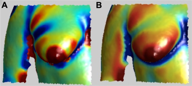
Types of curvature used for nipple identification. (A) Gaussian Curvature, K (B) Mean Curvature, H.
Features for nipples included high ellipticity and convexity curvature values (red and orange colored regions, H > 0 and K > 0) and a maximal value along the z-axis (ie, outward projection). To simultaneously search for these criteria, the sum of the curvature values, H and K and the corresponding z-value for each vertex on the surface mesh, was computed and the point having the largest sum was selected as the initial estimate of the nipple. Including the corresponding 2D color information available for the surface mesh as follows refined this initial estimate. The 3D surface mesh region surrounding the initial estimated nipple position (as shown in Fig. 2A) was extracted by traversing the mesh and selecting vertices in subsequent 1-ring neighborhoods until a maximum of 400 vertices were identified.22 Next the area exhibiting the highest Gaussian curvature (red in Fig. 2A) in the extracted sub-region and its corresponding color map were determined (Fig. 2B). The rationale here was to differentiate the areola region and a portion of the surrounding breast mound, but not the entire breast. This color map was converted to gray-scale (as shown in Fig. 2C) and then binarized using automated thresholding. For thresholding, the maximum (Imax) and minimum (Imin) intensity values of the pixels present in the gray-scale map (from the 2D color image) of the sub-region (Fig. 2C) were determined. Pixels with values less than Imin + 0.1 (Imax − Imin) were assigned a value of 1, and the remaining pixels were assigned a value of 0. This thresholding criterion is based on the assumption that the nipple is more heavily pigmented than the surrounding areola. Thresholding allows the selection of points that are within 10% of the total contrast observed in nipple-areola sub-region. The centroid of the binarized sub-region was computed and remapped back to the 3D mesh, giving the final location of the nipple on the surface. These procedures were performed on each of the partitioned halves of the torso surface, left and right, to determine NL and NR, respectively (Fig. 3).
Figure 2.

Steps for nipple identification (A) Gaussian curvature plot of the region extracted using initial estimate of the nipple (B) 2D texture image of the high curvature region (red colored) exhibited in the Figure 2A (C) gray-scale image of 2D texture image (D) output after thresholding the gray-scale image.
Figure 3.
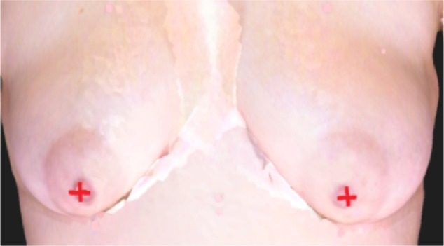
Position of automatically detected nipples (red cross).
Identification of sternal notch
The sternal notch is a visible dip just between the heads of the clavicles located along the midline at the base of the neck. To automatically detect the sternal notch, we locate the midpoint of the upper portion of the region at the intersection of the neck and the torso. To determine the point of the intersection of the torso with the neck, the width of the torso (xmax − xmin) is determined along the length (ie, moving upward from the breast mounds towards the neck) (Fig. 4A). At the point of transition from the torso to the neck, there is a large decrease in the width (Fig. 4A, indicated as point P1). At point P1, the midpoint of width ((xmax − xmin)/2) is computed, and the search for the sternal notch is restricted to a region within 10% of this midpoint along x-axis.
Figure 4.
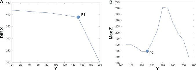
(A) Xmax − Xmin (diff X) against a range of Y-coordinates. P1 is the point after which the graph ceases to be constant. (B) Maximum Z along midpoint of X, plotted against a range of Y-coordinates.
Note: P2 is the initial estimate for the y-coordinate that is used to define the vertical extent of the search region for the sternal notch.
Similarly, plotting the maximum z-values along the midpoint of the width (determined above), against the y-coordinates (moving downward from the neck to the breast mounds), we find the vertical extent of search region (Fig. 4B). As seen in Figure 4B, the point P2 is indicative of the area where the sternal notch begins to dip. We define the vertical extent of the ROI for the sternal notch as the region 15% above and below the point P2. The final ROI for determination of the sternal notch is as shown in Figure 5A. The principal curvature of the ROI is then computed to locate the sternal notch. As shown in Figure 5B (blue area), the sternal notch exhibits low principal curvature, kmin < 0. Within the region exhibiting kmin < 0, the point with the minimal z-value (indicating the dip of the sternal notch) is determined as the location of sternal notch. Figure 5C shows the location of the sternal notch automatically detected using the proposed algorithm.
Figure 5.
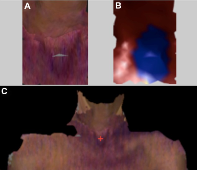
(A) ROI for determination of sternal notch. (B) Principal Curvature image of the ROI for sternal notch. (C) Sternal notch (red cross) located by the algorithm.
Identification of umbilicus
To identify the location of the umbilicus we used the Shape Index (S) curvature and the Mean curvature (H) values.24 We restricted our search region to the bottom 40% and central 30% of the torso as this represents the anatomical region where the umbilicus is located. The umbilicus region exhibits a high elliptical concave curvature (blue colored region, S < 0 and H < 0 as shown in Fig. 6A and B). Thus, we extracted the regions exhibiting concavity (blue color) for both S as well as the H curvatures. We also extracted the corresponding 2D color values for the same set of points as shown in Figure 6C. The final position of the umbilicus was then estimated by the centroid of the extracted 2D color image. This centroid point was remapped on to the 3D torso image giving the final estimate of the location of the umbilicus.
Figure 6.
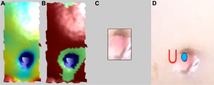
Steps for umbilicus identification (A) H-plot (B) S-plot (C) Extracted umbilicus region (D) Detected umbilicus (blue dot).
Imaging system
The 3D images used in this study were captured using two stereophotogrammetric systems, namely, the DSP800 and 3dMDTorso systems manufactured by 3Q Technologies Inc., Atlanta, GA. The latest version, the 3dMDTorso, has improved accuracy enabling capture of 3D data clouds of ∼75,000 points, whereas the older system, the DSP800, allows capture of data clouds consisting of ∼15,000 points. Data from the two different systems were used to study the influence of the resolution of the 3D point cloud on the performance of the algorithms proposed. Each reconstructed surface image consists of a 3D point cloud, ie, x, y, z coordinates, and the corresponding 2D color map. Only the frontal portion of the torso is imaged, resulting in a surface mesh which excludes the back region.
Study population
Women who had both native breasts (unoperated) were recruited for this study at The University of Texas MD Anderson Cancer Center under a protocol approved by the institutional review board. The subjects in the study consisted of 19 patients who were preparing to undergo a mastectomy and breast reconstruction, and 5 commissioned participants. The nineteen patients ranged in age from 36 to 63 years (51.2 ± 7.6) with body mass index (BMI) in the range of 20.4 to 38.6 kg/m2 (25.9 ± 4.7). Out of the nineteen patients, four were Hispanic/Latino and fifteen were not Hispanic/Latino. Eighteen patients were white and one was African American. Race, ethnicity, age, and BMI information was not available for the five commissioned female volunteers.
Study protocol
All the subjects signed informed consent forms, were taken to a private research area where they disrobed, and had one/two sets of images taken in the hands down pose.6 For the first set, which we refer to as the “unmarked images,” no markings were made on the subject prior to the image being taken. For the second set, prior to capturing the image, an experienced research nurse manually marked the fiducial points directly on the subject; we denote the resulting picture as the “marked image.” Both unmarked and marked torso images were acquired using the DSP800 system, whereas only unmarked images were acquired using the 3dMDTorso system. In order to validate stereophotometry, direct anthropometric data (ie, marked images) were initially collected only on subjects imaged with the DSP800 system.3 Following validation of distance measurements using stereophotometry, manual markings and measurements were not performed on subjects when using the upgraded 3dMDTorso system.
Twelve images obtained using each the DSP800 and 3dMDTorso systems were used as test data sets. In addition, another twelve images (randomly selected) from patients and volunteers obtained using the DSP800 system were used as the training data set for algorithm development (data not included). Information regarding height and weight was abstracted from patient’s medical record. Four naïve observers (graduate students) were briefly instructed to manually annotate the fiducial points on the acquired images (both marked and unmarked). For unmarked images, the four observers manually (via mouse click using software) identified the fiducial points on the torso images. Each observer selected and recorded the location of the fiducial points. For marked images, one of the four observers recorded the x, y, z coordinates of the annotated points on the images. In addition to the coordinates of fiducial points, we also computed the contoured distances (eg, nipple-to-nipple distance) between the fiducial points using customized software.3,6 The contoured distance was the shortest geodesic path along the 3D surface of subject’s torso between two points and computed using the “continuous dijkstra” algorithm described by Mitchell et al.25 As discussed earlier for the marked images for the DSP800 system, the research nurse manually recorded anthropometric distance measurements (eg, nipple-to-nipple distance) between the manually marked fiducial points using a tape measure. Fiducial points markings on the subject made by the research nurse and the manually measured distances between these points using the tape measure were designated as the ground truth for images from the DSP800, while for unmarked images from the 3dMDTorso system, manually selected points on images (stereophotometry by observers) and the corresponding computed contoured (geodesic) distances were used as the ground truth.
Data analyses
We evaluated the performance of the proposed algorithms by (1) comparing the 3D coordinates of fiducial points, (2) comparing distances between fiducial points, and (3) determining the precision of fiducial point detection. Performance of fully automated stereophotometry (automated fiducial point detection from marked and unmarked images with automated computation of geodesic distance) was compared against manual stereophotometry (manual annotation of fiducial points on unmarked images with automated computation of geodesic distance), and/or direct anthropometry (marked images showing fiducial points directly annotated on the participant, and distances recorded directly on the participant using a tape measure).
Comparison of 3D coordinates
In order to compare the spatial coordinates or position of the points located via different methods (automated stereophotometry, manual stereophotometry, and direct anthropometry), we calculated the geodesic distance between automatically detected coordinates and those annotated manually.
Comparison of geodesic distances between fiducial points
Typically quantitative assessments of breast morphology include the use of distances between fiducial points to define appearance in terms of measures such as symmetry4 and ptosis.5 Thus, we evaluated the hypothesis that distances measured using the three methods are equivalent. For manual stereophotometry measurements, we used the average of measurements from the four observers. In tests such as the Student’s t-test and ANOVA, the null hypothesis is that the means of the groups under comparison are the same, and the alternative hypothesis is that the group means are different. Thus, they cannot prove that a state of no difference between groups exists.26 We used equivalency testing to demonstrate comparability by examining whether mean differences between any two groups are small enough that these differences can be considered practically acceptable and, thus, the groups can be treated as equivalent. For equivalence testing, we computed the (1 – 2α), ie, the 90% confidence interval at a significance level of α = 0.05 around the mean difference between two groups.26 In addition, we also performed significance testing using the nonequivalence null hypothesis (ie, the two one-sided tests; TOST).27
Precision of fiducial point detection
We determined the precision accuracy of the algorithms by calculating relative error magnitude (REM),28 as the percentage of the difference between two measurements divided by the grand mean of the two sets of measurements. Precision REM scores less than 1% are deemed “excellent”; between 1% and 3.9% as “very good”; between 4% and 6.9% as “good”; between 7% and 9.9% as “moderate”; and any scores above 10% as “poor.”29
Results
Comparison of 3D coordinates
Automated identification of nipples (NR and NL), sternal notch, and umbilicus was performed on 12 (unmarked and marked) images from the DSP800, and 12 (unmarked) images from the 3dMDTorso system. For images from the DSP800, both marked and unmarked images from one participant exhibited irregularities in the surface mesh due to noise, and thus the images were deemed unusable due to overall poor quality of the image (Fig. 7). The algorithms successfully located the 44 nipples in 22 images (including both unmarked and marked) acquired from DSP800, and 24 nipples in 12 images from the 3dMDTorso system. Similarly both the sternal notch and umbilicus were successfully located in all the images analyzed. Table 1 presents a comparison of the 3D coordinates for the three fiducial points identified by automated and manual stereophotometry, and direct anthropometry in terms of the average difference (ie, the distance between the pair of coordinates being compared). The overall average difference for both NL and NR was found to be 8.0 ± 4.4 mm for unmarked images, and 5.8 ± 3.6 mm for marked images from the DSP800. It is interesting to note that automated stereophotometry compares more favorably to direct anthropometry than manual stereophotometry. A plausible explanation is that manual stereophotometry may be subject to operator bias, thereby introducing a larger discrepancy in the identification of fiducial points. For images from the 3dMDTorso system, we observed improved results, as the image resolution is higher. The overall average difference for the detection of 24 nipples from 12 unmarked images was found to be 5.2 ± 2.4 mm.
Figure 7.
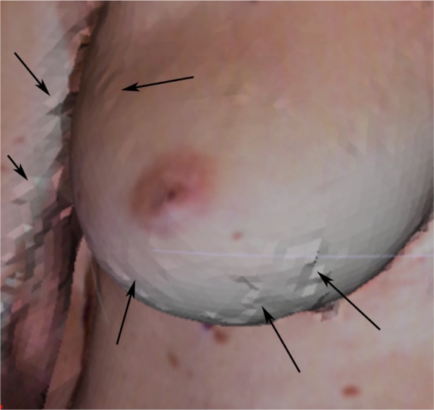
Anomalies due to noise in the surface mesh are visible (see arrows).
Table 1.
Comparison of the 3D coordinates for the three fiducial points identified by automated and manual stereophotometry, and direct anthropometry in terms of the average difference (ie, the geodesic distance between the pair of coordinates being compared).
| Type of comparison | Instrument | Average difference [μ ± σ (mm)]
|
||
|---|---|---|---|---|
| Nipples (#) | Sternal notch (#) | Umbilicus (#) | ||
| Manual stereophotometry vs. automated | DSP800 | 8.0 ± 4.4 (22) | 19.4 ± 10.0 (11) | 8.2 ± 6.5 (11) |
| 3dMDTorso | 5.2 ± 2.4 (24) | 14.0 ± 6.5 (12) | 4.4 ± 3.0 (12) | |
| Direct anthropometry vs. automated | DSP800 | 5.8 ± 3.6 (22) | 22.4 ± 6.5 (11) | 11.5 ± 10.9 (11) |
Note: The number of images (#), evaluated for each fiducial point is denoted within parentheses.
For sternal notch identification, the average difference between automated and manual stereophotometry was found to be 19.4 ± 10.0 mm and 14.0 ± 6.5 mm, for the DSP800 and 3dMDTorso systems, respectively. As expected, improved identification is observed for the 3dMDTorso system due to its higher image resolution. Based on the average size of sternal notch (∼40 mm),30 any difference ≤ 20 mm (50% of the mean size) indicates that the position of the sternal notch detected by the automated approach would fall well within the overall sternal notch region. The comparison of automated stereophotometry with direct anthropometry indicated an average difference of 22.4 ± 6.5 mm. In this case, higher variability is observed because manual annotation of the sternal notch directly on the participant’s torso was marked by the research nurse and the four naïve observers at a point on the chest surface representing the point midway between the left and right clavicles (and not within the valley of the sternal notch), whereas the algorithm identifies the dip (maximal inward projection or depth) as the sternal notch.
For umbilicus identification, the average difference between automated and manual stereophotometry was found to be 8.2 ± 6.5 mm and 4.4 ± 3.0 mm for the DSP800 and 3dMDTorso systems, respectively. The umbilicus represents the attachment site of the umbilical cord and is visible as a depressed scar surrounded by a natural skin fold that measures about 15–20 mm in diameter.31,32 Typically, the surrounding navel ring is about 20–25 mm with an inner depressed region of approximately 10–15 mm. The average difference between the umbilicus marked by the research nurse (direct anthropometry) and that detected by our algorithm (automated stereophotometry) was found to be 11.5 ± 10.9 mm. This relatively larger discrepancy is a result of the practical difficulty associated with manual marking of the umbilicus on the participant. The umbilicus forms a depression on the skin of the abdomen, making it too difficult to visualize a mark within the center of the umbilicus on 3D images. The research nurse marked the umbilicus just above its physical location (Fig. 8) to facilitate the visibility of the mark for subsequent direct anthropometry and manual stereophotogrammetric of distances, whereas the algorithm identified the point of maximal depression as the umbilicus resulting in the larger variance observed between the two methods.
Figure 8.
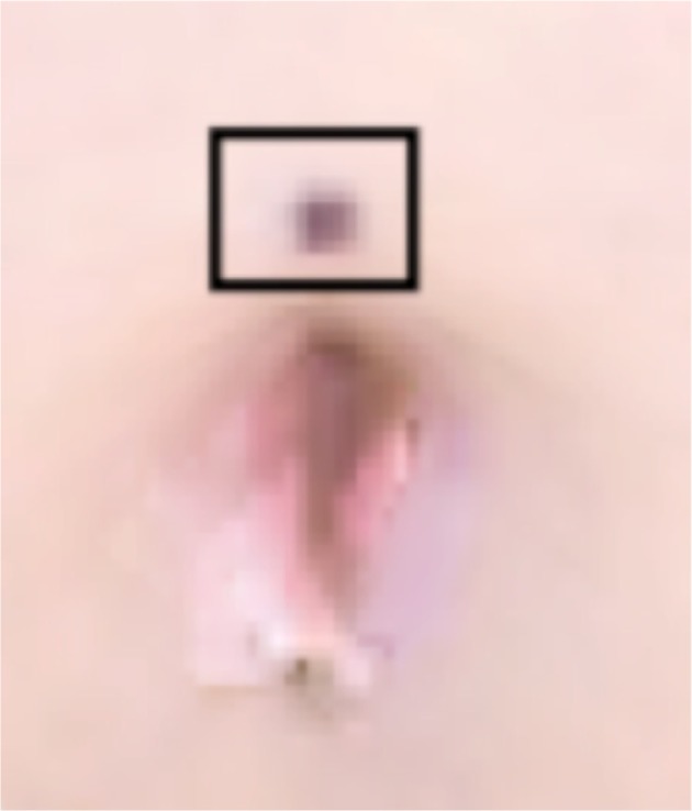
Annotation of the umbilicus directly on the subject by the research nurse.
Note: The marking made by the nurse is highlighted by the black box.
Comparison of geodesic distance
We performed equivalence testing to compare the nipple-to-nipple (NL-NR), sternal notch-to-NL, sternal notch-to-NR, and sternal notch-to-umbilicus geodesic distances between three groups (automated stereophotometry, manual stereophotometry, and direct anthropometry). This analysis was performed using the marked images captured with the DSP800 (N = 11 subjects; Table 1), since direct anthropometric data was not available for images captured using the 3dMDTorso system. For equivalence testing, the practically acceptable discrepancy (Δ) for the NR-NL, sternal notch-to-NR, and sternal notch-to-NL distances was defined to be 1.6 cm (∼7% of the average nipple-to-nipple distance). This criterion was based on anthropometric measurements of the diameter of the nipple,33 which is estimated to be in the range of 1.0–2.6 cm with a mean value of ~1.8 cm. Thus Δ = 1.6 cm effectively represents a practically acceptable value because a difference ≤ 1.6 cm between the NR-NL distances measured using different methods can be deemed negligible as it approximates a value slightly lower than the average size of a single nipple. Similarly, for the sternal notch-to-umbilicus distance, we predefined Δ = 4.5 cm resulting in an equivalence interval of [−4.5, 4.5]. The distance between the sternal notch and the umbilicus is about 40–45 cm; the average width of the sternal notch30 is ∼4.8 cm, whereas the diameter of the umbilicus is highly variable ranging from 1.5 to 2.5 cm based on its shape.31 Given the normal variability in the size and shape of both the sternal notch and the umbilicus, we chose the smallest amount of practically acceptable difference between the distance measured using automated versus manual methods to be 10% of the sternal notch-to-umbilicus distance, ie, 4.5 cm. This analysis was performed using the images (N = 11) captured with the DSP800, resulting in a total of 11 NR-to-NL, 22 sternal notch-to-nipple (11 from the sternal notch-to-NR and 11 from the sternal notch-to-NL), and 11 sternal notch-to-umbilicus distance measurements. We performed a pairwise comparison of the distances measured by automated stereophotometry, manual stereophotometry, and direct anthropometry. All the three groups were found to be equivalent, with the confidence intervals falling within the equivalence interval. Based on TOST for both the one-sided tests, we reject the null hypothesis to confirm equivalence within the specified Δ value (P-values in Table 2).
Table 2.
Summary of equivalence testing.
| Distance | Groups | 90% CI | TOST H0 | P-value |
|---|---|---|---|---|
| NR-NL (N = 11) | Auto vs. direct | −1.5674, 0.4420 | μAuto-μDirect ≤ −1.6 | 0.0454 |
| μAuto-μDirect ≥ 1.6 | 0.0015 | |||
| Manual vs. direct | −1.3605, 0.5969 | μMan-μDirect ≤ −1.6 | 0.0239 | |
| μMan-μDirect ≥ 1.6 | 0.0022 | |||
| Auto vs. manual | −0.4685, 0.1067 | μAuto-μMan ≤ −1.6 | 0.0000 | |
| μAuto-μMan ≥ 1.6 | 0.0000 | |||
| Sternal notch-to-nipple (N = 22) | Auto vs. direct | 0.5330, 1.5143 | μAuto-μDirect ≤ −1.6 | 0.0000 |
| μAuto-μDirect ≥ 1.6 | 0.0281 | |||
| Manual vs. direct | 0.0869, 0.7199 | μMan-μDirect ≤ −1.6 | 0.0000 | |
| μMan-μDirect ≥ 1.6 | 0.0000 | |||
| Auto vs. manual | 0.2242, 1.0163 | μAuto-μMan ≤ −1.6 | 0.0000 | |
| μAuto-μMan ≥ 1.6 | 2.0E-04 | |||
| Sternal notch-to-umbilicus (N = 11) | Auto vs. direct | −1.5674, 0.4420 | μAuto-μDirect ≤ −4.5 | 0.0000 |
| μAuto-μDirect ≥ 4.5 | 0.0219 | |||
| Manual vs. direct | −1.3605, 0.5969 | μMan-μDirect ≤ −4.5 | 0.0000 | |
| μMan-μDirect ≥ 4.5 | 1.0E-04 | |||
| Auto vs. manual | −0.4685, 0.1067 | μAuto-μMan ≤ −4.5 | 0.0000 | |
| μAuto-μMan ≥ 4.5 | 0.0000 |
Precision analysis
Finally, we determined the precision of the automated algorithm by calculating the REM for the NR-NL, sternal notch-to-nipple, and sternal notch-to-umbilicus distances measured using automated and manual stereophotometry. We performed this analysis only for the 3dMdSystem as the DSP800 system is no longer commercially available. REM was computed by dividing the difference between two measurements by the grand mean of both the measurements together. Table 3 presents the REM values. These results validate the effectiveness of automated stereophotometry for the analysis of breast morphology.
Table 3.
Precision analysis of automated stereophotometry with reference to manual stereophotometry.
| Distance (auto vs. manual) | Total | REM | Precision |
|---|---|---|---|
| NL-NR | 11 | 1.9% | “Very good” |
| Sternal notch-to-nipple | 22 | 3.0% | “Very good” |
| Sternal notch-to-umbilicus | 11 | 1.8% | “Very good” |
Discussion
Breast morphology can be quantified by geometric measurements made on 3D surface images. Inherent to all geometric measures is the identification of fiducial points. For example, using the nipples and sternal notch, symmetry is often computed as a ratio of the distance between the nipples and the sternal notch.6 In order to facilitate automated analysis, as a first step in this study we describe the automated identification of three key fiducial points, namely the right and left nipples, sternal notch, and umbilicus. We present a novel approach for automated identification of fiducial points in 3D images that are based on surface curvature. An advantage of using curvature, as a primary feature for the detection of fiducial points is that it is invariant to translation and rotation of the surface,34 thereby making the algorithms applicable to 3D images of the subject captured at any pose.
Performance of the algorithms is validated by comparing the fully automated approach to manual stereophotogrammetry (average of 4 observers), and to direct anthropometry, using two parameters: (1) the spatial location in terms of the (x, y, z) coordinates, and (2) the distance measured between fiducial points. This evaluation methodology allows us to test the reliability of the automated approach in terms of both the actual position of the fiducial points and the practical measurement of the distances that are clinically important. Finally, the precision of fiducial point detection is determined in terms of the REM.28
We have presented data acquired using two imaging systems from 3Q Technologies Inc.: the DSP800, an early generation model, and the 3dMDTorso, the latest instrument from the company. We were required to include the data from the DSP800 as corresponding direct anthropometric data from subjects was only available for this data set. The automated approaches presented were validated by comparison to direct anthropometry using images from the DSP800, but the final precision values were computed using images captured with the latest generation equipment which is current and affords improved imaging capabilities in terms of both speed and resolution.
For the detection of the fiducial points, we recorded a mean difference of ≤5 mm between manual stereophotometry and the proposed automated algorithms for the identification of the position of the nipple (5.2 ± 2.4 mm) and the umbilicus (4.4 ± 3.0 mm) for images acquired by the 3dMDTorso system, whereas the mean difference for the identification of the sternal notch (14.0 ± 6.5 mm) was found to be ≤15 mm. A plausible explanation for the relatively larger difference observed for the sternal notch in comparison to the nipple or umbilicus, is the physical size/extent of the individual fiducial points. The average size of the nipple and umbilicus31,33 is ∼20 mm, whereas the width of the sternal notch30 is ∼40 mm. Due to the larger area of the sternal notch, higher variability is expected in its manual annotation, which accounts for the larger difference observed between automated and manual stereophotometry. We have also previously shown that inter-observer variability6 for manual annotation of the sternal notch on 3D torso images is in the range of 7.8 to 9.4 mm. It should also be noted that when comparing the results of automated detection with manual annotation, a critical factor is the experience of the user who must rely on palpation to ascertain the location of non-bony fiducial points such as the sternal notch. Thus user bias in the manual annotation of the sternal notch may strongly influence the variability observed. Overall the proposed algorithms are able to identify the position of the three fiducial points within a distance that is half the size of the fiducial point itself, ie, difference ≤ 5 mm for nipples and umbilicus (mean size 10 mm), and difference ≤ 15 mm for the sternal notch (mean size 40 mm). This indicates that the position of the fiducial points detected by the automated approach fall well within the overall physical region of the fiducial points. As expected, the performance of the algorithm when compared to manual stereophotometry for images from the DSP800 is lower, ie, difference ≤ 8 mm for the nipple and umbilicus, and difference ≤ 20 mm for the sternal notch. This is an inherent effect of the lower resolution of the DSP800 system. Overall, our results indicate that the proposed algorithms were effective in detecting the position of the nipples, sternal notch, and umbilicus in 3D torso surface scans.
The comparison of automated stereophotometry with direct anthropometry for identification of the position of the fiducial points resulted in a difference of approximately 6 mm, 22 mm, and 12 mm for the nipples, sternal notch, and umbilicus, respectively. These values are slightly high, particularly for the umbilicus, for the following reasons. First, the resolution of the DSP800 system is low (approximately one third that of the 3dMDTorso). Second, a key factor contributing to this difference is the discrepancy in the marking of these points on the subject by the research nurse and the criteria on which the automated detection was implemented. For example, the umbilicus was marked on subjects just above the umbilicus (Fig. 8) since it is difficult to visualize an annotation marked within the umbilicus (i.e. at its center) in 3D images. The algorithm, on the other hand, selected the centroid within the navel ring that exhibited the maximal dip. Similarly, the sternal notch was automatically identified as point exhibiting the maximal dip in the valley between the two clavicles, whereas direct annotation was done at the point on the chest surface representing the point midway between the left and right clavicles. In contrast, the nipple has several distinct structural characteristics that make its manual identification relatively easier and, accordingly, we observed a smaller difference when comparing automated stereophotometry with direct anthropometry for nipple identification. Furthermore, nipples can be classified as everted, flat, or inverted based on their shape. Everted nipples are most common and appear as raised tissue in the center of the areola, whereas inverted nipples appear to be indented in the areola and flat nipples appear to have no shape or contour. In this study, 77% of the nipples were everted, 14% were flat and 9% were inverted. These findings suggest that the proposed algorithm can identify everted, flat, and inverted nipples but further evaluation (ie, a larger sample population) is needed to statistically evaluate the efficacy of algorithm to detect all nipple shapes.
Another important aspect with manual annotation of fiducial points (such as the sternal notch) on subjects is that it is typically performed via palpation of the skin and the underlying tissue and bone structures and thus the BMI of the subject can influence the markings. Figure 9 presents a plot of the difference between the manually and automatically annotated points versus the BMI for the 18 subjects (BMI was unavailable for the commissioned participants). As seen in the figure, the largest difference between the two approaches is observed for the sternal notch, but the difference for the nipples and umbilicus are fairly equivalent. Most importantly, we did not notice any differences when comparing the normal (39%), overweight (44%), and obese (17%) subjects. The ability of the automated algorithm was found to be equally effective in identifying fiducial points in normal (BMI = 18.5–24.9), overweight (BMI = 25–29.9), and obese (BMI ≥ 30) subjects. This may be attributed to the primary use of curvature as a feature to detect the points. Even in obese subjects, the subtleties of surface curvature for the anatomical landmarks remain and can be computationally measured to enable effective detection of the fiducial points. These subtle curvature changes may not be easily discernable during manual stereophotometry using images or when applying direct palpation on the subject.
Figure 9.
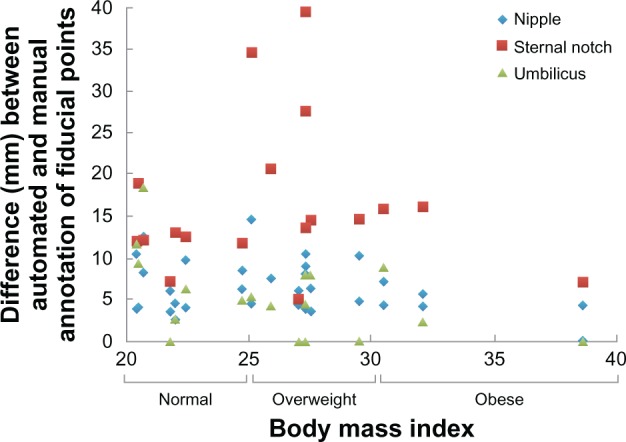
Plot of the difference between the manually and automatically annotated points versus the BMI.
Notes: Based on BMI, subjects were categorized as underweight (BMI < 18.5), normal (BMI = 18.5–24.9), overweight (BMI = 25–29.9) and obese (BMI ≥ 30).
Since an important purpose of identifying fiducial points is to facilitate quantitative distance measurements, we performed a pairwise comparison of the distances measured by automated stereophotometry, manual stereophotometry, and direct anthropometry. All of the three groups were found to be equivalent with the confidence intervals falling within the equivalence interval (Table 2). This suggests that automated identification of fiducial points can be used to facilitate robust quantitative assessment of distances from torso images. Finally, the REM for automated detection of all the points was found to be within the interval of 1%–3.9% indicating very good precision.
In summary, the algorithms presented satisfactorily identified all the fiducial points. This is the first attempt for the automated detection of fiducial points on 3D images for breast reconstructive surgery and should not only benefit the objective assessment of breast reconstruction but can also assist us in future research needed to better understand the relationship between objective outcomes of reconstruction and patient body image or subjective perception of cosmetic outcomes. Our findings can also be extended to the task of detecting landmark points in other areas such as for facial reconstruction surgeries, and other surgeries on human torso. The curvature analysis used in our algorithms can be easily used for determining properties such as symmetry, curvature, and ptosis of the breasts, which are important characteristics used for defining the breast aesthetics.
Acknowledgments
The authors recognize the support and contributions of patient data that were generously provided by Geoff Robb, M.D. and Steven Kronowitz, M.D., of the Department of Plastic Surgery at The University of Texas MD Anderson Cancer Center for use in this study.
Footnotes
Author Contributions
Conceived design of image analysis algorithms: MMK, FAM. Analyzed the data: MMK, FAM. Participant Recruitment and Management: MCF, GPR, MAC, EKB. Wrote the first draft of the manuscript: MMK, FAM. Contributed to the writing of the manuscript: MMK, FAM, GPR, MAC, EKB, MCF, MKM. Agree with manuscript results and conclusions: MMK, FAM, GPR, MAC, EKB, MCF, MKM. Jointly developed the structure and arguments for the paper: MMK, FAM, GPR, MAC, EKB, MCF, MKM. Made critical revisions and approved final version: MMK, FAM, GPR, MAC, EKB, MCF, MKM. All authors reviewed and approved of the final manuscript.
Funding
This work was supported in part by NIH grant 1R01CA143190-01A1 and American Cancer Society grant RSGPB-09-157-01-CPPB.
Competing Interests
Authors disclose no potential conflicts of interest. Dr Elisabeth Beahm passed away after this paper was submitted. A disclosure of competing interests consequently could not be obtained.
Disclosures and Ethics
As a requirement of publication the authors have provided signed confirmation of their compliance with ethical and legal obligations including but not limited to compliance with ICMJE authorship and competing interests guidelines, that the article is neither under consideration for publication nor published elsewhere, of their compliance with legal and ethical guidelines concerning human and animal research participants (if applicable), and that permission has been obtained for reproduction of any copyrighted material. This article was subject to blind, independent, expert peer review. The reviewers reported no competing interests.
References
- 1.Eriksen C, Lindgren EN, Olivecrona H, Frisell J, Stark B. Evaluation of volume and shape of breasts: comparison between traditional and three-dimensional techniques. J Plast Surg Hand Surg. 2011 Feb;45(1):14–22. doi: 10.3109/2000656X.2010.542652. [DOI] [PubMed] [Google Scholar]
- 2.Moyer HR, Carlson GW, Styblo TM, Losken A. Three-dimensional digital evaluation of breast symmetry after breast conservation therapy. J Am Coll Surg. 2008 Aug;207(2):227–32. doi: 10.1016/j.jamcollsurg.2008.02.012. [DOI] [PubMed] [Google Scholar]
- 3.Lee J, Kawale M, Merchant FA, et al. Validation of stereophotogrammetry of the human torso. Breast Cancer (Auckl) 2011;5:15–25. doi: 10.4137/BCBCR.S6352. [DOI] [PMC free article] [PubMed] [Google Scholar]
- 4.Van Limbergen E, van der Schueren E, Van Tongelen K. Cosmetic evaluation of breast conserving treatment for mammary cancer. 1. Proposal of a quantitative scoring system. Radiother Oncol. 1989 Nov;16(3):159–67. doi: 10.1016/0167-8140(89)90016-9. [DOI] [PubMed] [Google Scholar]
- 5.Kim MS, Reece GP, Beahm EK, Miller MJ, Atkinson EN, Markey MK. Objective assessment of aesthetic outcomes of breast cancer treatment: measuring ptosis from clinical photographs. Comput Biol Med. 2007 Jan;37(1):49–59. doi: 10.1016/j.compbiomed.2005.10.007. [DOI] [PubMed] [Google Scholar]
- 6.Kawale M, Lee J, Leung SY, et al. 3D Symmetry measure invariant to subject pose during image acquisition. Breast Cancer (Auckl) 2011;5:131–42. doi: 10.4137/BCBCR.S7140. [DOI] [PMC free article] [PubMed] [Google Scholar]
- 7.Hartkens T, Rohr K, Stiehl HS. Evaluation of 3D operators for the detection of anatomical point landmarks in MR and CT images. Computer Vision Image Understanding. 2002;86(2):118–36. [Google Scholar]
- 8.Subburaj K, Ravi B, Agarwal M. Automated identification of anatomical landmarks on 3D bone models reconstructed from CT scan images. Comput Med Imaging Graph. 2009 Jul;33(5):359–68. doi: 10.1016/j.compmedimag.2009.03.001. [DOI] [PubMed] [Google Scholar]
- 9.Lubbers HT, Medinger L, Kruse A, Gratz KW, Matthews F. Precision and accuracy of the 3dMD photogrammetric system in craniomaxillofacial application. J Craniofac Surg. 2010 May;21(3):763–7. doi: 10.1097/SCS.0b013e3181d841f7. [DOI] [PubMed] [Google Scholar]
- 10.Scheenstra A, Ruifrok A, Veltkamp RC. (Lecture notes in computer science).A survey of 3D face recognition methods. 2005;3546:891–9. [Google Scholar]
- 11.Ehrhardt J, Handels H, Plotz W, Poppl SJ. Atlas-based recognition of anatomical structures and landmarks and the automatic computation of orthopedic parameters. Methods Inf Med. 2004;43(4):391–7. [PubMed] [Google Scholar]
- 12.Gokberk B, Irfanoglu MO, Akarun L. 3D shape-based face representation and feature extraction for face recognition. Image Vision Computing. 2006;24(8):857–69. [Google Scholar]
- 13.Wang Y, Chua C-S, Ho YK. Facial feature detection and face recognition from 2D and 3D images. Pattern Recognition Letters. 2002;23(10):1191–202. [Google Scholar]
- 14.Wang YM, Pan G, Wu ZH, Han S. Sphere-Spin-Image: A Viewpoint-Invariant Surface Representation for 3D Face Recognition; Computational Science—Iccs 2004, Pt 2, Proceedings; pp. 427–34. [Google Scholar]
- 15.Wu ZH, Wang YM, Pan G. 3D Face Recognition Using Local Shape Map; Icip: 2004. International Conference on Image Processing; pp. 2003–6. [Google Scholar]
- 16.Huang HQ, Mok PY, Kwok YL, Au JS. Determination of 3D necklines from scanned human bodies. Textile Research Journal. 2011 May;81(7):746–56. [Google Scholar]
- 17.Wang QM, Ressler S. Generation and manipulation of h-anim CAESAR scan bodies; Web3d 2007 12th International Conference on 3D Web Technology, Proceedings; 2007. p. 191. [Google Scholar]
- 18.Wang Y, Li J, Wang H, Hou Z. Automatic nipple detection using shape and statistical skin color information. Advances in Multimedia Modeling. 2010;5916:644–9. [Google Scholar]
- 19.Dabeer M, Kim E, Reece GP, et al. Automated calculation of symmetry measure on clinical photographs. J Eval Clin Pract. 2011 Dec;17(6):1129–36. doi: 10.1111/j.1365-2753.2010.01477.x. [DOI] [PMC free article] [PubMed] [Google Scholar]
- 20.Cardoso JS, Sousa R, Teixeira LF, Carlson MJ. Breast Contour Detection with Stable Paths; Paper presented at: Communications in Computer and Information Science; 2008. [Google Scholar]
- 21.Gordon GG. Face recognition based on depth maps and surface curvature. Geometric Methods in Computer Vision. 15701991:234–47. [Google Scholar]
- 22.Peyre G. Toolbox Graph. 2004. [Accessed Nov 1, 2012]. (A toolbox to perform computations on graph). http://www.mathworks.com/matlabcentral/fileexchange/5355-toolbox-graph.
- 23.Cohen-Steiner D, Verdiere EC, Yvinec M. Conforming Delaunay triangulations in 3D. Comput Geom-Theory Applic. 2004 Jun;28(2–3):217–33. [Google Scholar]
- 24.Cantzler H, Fisher RB. Comparison of HK and SC Curvature Description Methods; Third International Conference on 3-D Digital Imaging and Modeling, Proceedings; 2001. pp. 285–91. [Google Scholar]
- 25.Mitchell JSB, Mount DM, Papadimitriou CH. The Discrete Geodesic Problem. SIAM J Comput. 1987;16(4):647–68. [Google Scholar]
- 26.Barker LE, Luman ET, McCauley MM, Chu SY. Assessing equivalence: an alternative to the use of difference tests for measuring disparities in vaccination coverage. Am J Epidemiol. 2002 Dec 1;156(11):1056–61. doi: 10.1093/aje/kwf149. [DOI] [PubMed] [Google Scholar]
- 27.Schuirmann DJ. A comparison of the two one-sided tests procedure and the power approach for assessing the equivalence of average bioavailability. J Pharmacokinet Biopharm. 1987 Dec;15(6):657–80. doi: 10.1007/BF01068419. [DOI] [PubMed] [Google Scholar]
- 28.Weinberg SM, Naidoo S, Govier DP, Martin RA, Kane AA, Marazita ML. Anthropometric precision and accuracy of digital three-dimensional photogrammetry: comparing the Genex and 3dMD imaging systems with one another and with direct anthropometry. J Craniofac Surg. 2006 May;17(3):477–83. doi: 10.1097/00001665-200605000-00015. [DOI] [PubMed] [Google Scholar]
- 29.Chong AK, Mathieu R. Near infrared photography for craniofacial anthropometric landmark measurement. Photogrammetric Record. 2006 Mar;21(113):16–28. [Google Scholar]
- 30.Mukhopadhyay PP. Determination of Sex from Adult Sternum by Discriminant Function Analysis on Autopsy Sample of Indian Bengali Population: A New Approach. J Indian Acad Forensic Med. 2010;32(4):321–4. [Google Scholar]
- 31.Craig SB, Faller MS, Puckett CL. In search of the ideal female umbilicus. Plast Reconstr Surg. 2000 Jan;105(1):389–92. doi: 10.1097/00006534-200001000-00062. [DOI] [PubMed] [Google Scholar]
- 32.Baack BR, Anson G, Nachbar JM, White DJ. Umbilicoplasty: the construction of a new umbilicus and correction of umbilical stenosis without external scars. Plast Reconstr Surg. 1996 Jan;97(1):227–32. doi: 10.1097/00006534-199601000-00038. [DOI] [PubMed] [Google Scholar]
- 33.Avsar DK, Aygit AC, Benlier E, Top H, Taskinalp O. Anthropometric breast measurement: a study of 385 Turkish female students. Aesthet Surg J. 2010 Jan;30(1):44–50. doi: 10.1177/1090820X09358078. [DOI] [PubMed] [Google Scholar]
- 34.Ho HT, Gibbins D. Curvature-based approach for multi-scale feature extraction from 3D meshes and unstructured point clouds. IET Computer Vision. 2009;3(4):201–12. [Google Scholar]


