

Abstract
Motivation: Recently, confocal light sheet microscopy has enabled high-throughput acquisition of whole mouse brain 3D images at the micron scale resolution. This poses the unprecedented challenge of creating accurate digital maps of the whole set of cells in a brain.
Results: We introduce a fast and scalable algorithm for fully automated cell identification. We obtained the whole digital map of Purkinje cells in mouse cerebellum consisting of a set of 3D cell center coordinates. The method is accurate and we estimated an F1 measure of 0.96 using 56 representative volumes, totaling 1.09 GVoxel and containing 4138 manually annotated soma centers.
Availability and implementation: Source code and its documentation are available at http://bcfind.dinfo.unifi.it/. The whole pipeline of methods is implemented in Python and makes use of Pylearn2 and modified parts of Scikit-learn. Brain images are available on request.
Contact: paolo.frasconi@unifi.it
Supplementary information: Supplementary data are available at Bioinformatics online.
1 INTRODUCTION
Understanding the cytoarchitecture of the mammalian central nervous system on a brain-wide scale is becoming a compelling need in neuroscience (Kasthuri and Lichtman, 2007; Sporns et al., 2005). In fact, single-neuron projections often span through the whole encephalon (Lichtman and Denk, 2011), supporting functional connection between anatomically distant regions. Therefore, charting cellular localizations and projections throughout the whole brain is a mandatory step to afford a comprehensive view of brain function. Many efforts are thus devoted to build cellular-resolution, brain-wide neuroanatomical atlases of the mouse brain (Bohland et al., 2009; Kleinfeld et al., 2011; Oh et al., 2014). Such maps would eventually allow characterizing on a structural basis the physiology and pathology of the central nervous system at various stages, ranging from development to neurodegeneration.
To map the structure of the mouse brain, in the past years several high-throughput imaging techniques have been developed. Electron microscopy coupled with automatic tissue sectioning has been exploited to reconstruct neuronal wiring with nanometric resolution (Briggman et al., 2011; Knott et al., 2008); however, its use is still limited to small brain regions because the slow imaging rates makes whole-brain measurements impossible at the moment (Briggman and Bock, 2011). On the other hand, optical methods have coarser resolution, but can be used to image the entirety of mouse brain (Osten and Margrie, 2013).
The three main optical approaches used to map mouse brain anatomy are micro-optical sectioning tomography (MOST) (Li et al., 2010; Mayerich et al., 2008), serial two-photon tomography (STP) (Ragan et al., 2012) and light sheet microscopy (LSM) (Keller and Dodt, 2012). The former technique allows mouse brain reconstruction with high contrast and resolution in 3D, but imaging time can reach even 1 month for a single brain (Gong et al., 2013). STP shows the excellent contrast and resolution characteristic of multiphoton microscopy, but it operates with rough axial sampling [1 μm section every 50 μm (Ragan et al., 2012)] and to our knowledge no full sampling reconstruction of a whole mouse brain has been demonstrated with this technique. LSM, coupled with chemical clearing procedures to render the brain transparent (Becker et al., 2012; Chung et al., 2013), permits reconstruction of the whole mouse brain with micron-scale resolution in a timescale ranging from hours to a few days (Dodt et al., 2007). The contrast affordable with this latter method is usually lower than the one of MOST and STP, because of residual light scattering inside the cleared tissue. However, LSM currently is the only method allowing acquiring a significant number of samples with full 3D resolution. Furthermore, an implementation called confocal light sheet microscopy (CLSM) shows 100% contrast increase with respect to conventional LSM, allowing to distinguish neuronal somata in whole-brain tomographies (Silvestri et al., 2012). In this technique, however, different fixation efficiencies within the whole organ and inhomogeneous optical clearing give rise to a large variability in contrast throughout the entire volume (as an example, three regions are shown at the top of Fig. 3). Because of this heterogeneity, naïve segmentation or localization methods (e.g. thresholding) cannot be applied to analyze whole-brain datasets obtained with CLSM.
Fig. 3.
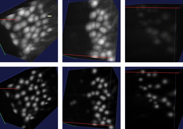
More examples of semantic deconvolution (substacks not included in the training set). Top: original images. Bottom: results of semantic deconvolution. Best viewed by zooming in a computer screen
The availability of advanced imaging techniques for whole brain mapping introduces the new challenge of extracting quantitative human-readable information from the data (Helmstaedter et al., 2011). There exist several proposals for automatic localization or segmentation of cell bodies in 2D (Buggenthin et al., 2013; Navlakha et al., 2013) and 3D microscopy (Forero et al., 2010; LaTorre et al., 2013; Quan et al., 2013). Forero et al. (2010) presented a method based on image filtering and object morphology analysis that automatically counts the number of dying cells in images of Drosophila embryos collected at the confocal microscope. The method was tested on small stacks of 130MVoxels and it attained a recall, precision and F1 of 0.98, 0.97 and 0.97, respectively (see Section 3.1.2 for definitions). LaTorre et al. (2013) propose an algorithm for segmenting neuronal mouse cells in 3D images of somatosensory cortex of 14 day old rats collected using a confocal laser scanner. The method, which needs information obtained in a 2D segmentation stage, was tested on a volume containing, in total, 600–700 neurons belonging to three different cortical layers (15.4 MVoxels). This method achieved a recall, precision and F1 ranging in (0.95, 0.99), (0.94, 0.95) and (0.95, 0.97), respectively. Quan et al. (2013) presented a neuron soma localization method, based on a minimization problem, which was tested on an image dataset of brain coronal profile of transgenic fluorescence mice (2–10 weeks old) collected using a fluorescence MOST system. The size of tested stack was voxels (361 MVoxels) and the algorithm localized ∼2500 neurons with a recall of 0.88.
In this article, we address the two major challenges that arise when attempting to perform information extraction from CLSM images: large datasets, and significant contrast heterogeneity. A mouse brain has a volume of the order of 1 cm3, yielding image sizes in the TeraByte scale at the micron-resolution. In these cases, the only alternative to the massive use of manwork [as in (Briggman et al., 2011)] is the development of fully automatic tools. To achieve this goal, the inherent contrast variability in CLSM requires sufficient robustness with respect to the parameters of the extraction algorithms: fine-tuning of parameters on different regions [as suggested e.g. by Quan et al. (2013)] may be practically unfeasible with images containing hundreds of thousands of neurons.
The method presented in this article is based on three core algorithmic ideas: mean shift clustering to detect soma centers (Section 2.2), supervised semantic deconvolution by means of neural networks for image enhancement (Section 2.3) and manifold learning for filtering false positives (FPs) (Section 2.4). The implementation makes use of Pylearn2 (Goodfellow et al., 2013) and modified parts of Scikit-learn (Pedregosa et al., 2011). To demonstrate its capabilities, we applied the algorithm to localize and count the Purkinje cells in the cerebellum of an L7-GFP mouse (Tomomura et al., 2001), a transgenic animal in which this neuronal population is labeled with enhanced green fluorescent protein (EGFP). We obtained an F1-measure of 0.96 and an area under the recall–precision curve of 0.97. To our knowledge, this is the first complete map of a selected neuronal population in a large area of the mouse brain.
2 MATERIALS AND METHODS
2.1 Materials
The images used for this study were obtained with CLSM, a method that combines the advantages of light sheet illumination with a confocal detection scheme. The protocol to obtain the images is described in detail in (Silvestri et al., 2012). Briefly, brain tissue is fixed with paraformaldehyde and subsequently cleared by substitution of water with a refractive-index-matching liquid (Becker et al., 2012; Dodt et al., 2007). The clearing procedure leads to isotropic tissue shrinkage of ∼20% in each direction, corresponding to a reduction of ∼50% in volume. Transparent brains are then imaged with the CLSM apparatus, which produces single-channel 8-bit TIFF files. The voxel size of the dataset presented here is 0.8 × 0.8 × 1 μm3. To collect the whole volume, many parallel adjacent image stacks are acquired by the apparatus. The stacks partially overlap with the neighbors, allowing subsequent alignment and fusion via a software tool designed to work with large dataset (TeraStitcher) (Bria and Iannello, 2012). Final data are saved as a non-redundant collection of non-overlapping stacks; copies of the dataset at lower resolutions are also saved, facilitating the visualization and 3D navigation of the whole image (Peng et al., 2014).
The main dataset analyzed is the whole cerebellum of a 10 day old L7-GFP mouse (Tomomura et al., 2001). In this transgenic animal, all Purkinje cells express EGFP, allowing visualization and mapping of this neuronal population.
2.2 Mean shift clustering
2.2.1 Substacking.
We begin by splitting the whole 3D image into a set of relatively small substacks of size . Partitioning the image has a number of advantages. First, it allows us to approximate a local-thresholding procedure (see Section 2.2.3) without incurring in the computational cost of fully fledged local thresholding algorithms (Sahoo et al., 1988). Second, dividing a large image in several substacks enables an immediate multi-core parallel implementation where each substack is processed separately in a different thread. Third, it is convenient to work on substacks during the manual annotation process (see Section 3.1.1), which is necessary to create the ground truth data used to estimate the quality of the predictions.
Substacks need to overlap to avoid border effects in the subsequent clustering procedure (see Section 2.2.2). The overlap length M was designed to ensure that every cell with a center detected inside the substack of size falls entirely within the substack of size (Fig. 1). In our images, the visible region of a Purkinje soma ranges between 11 and 18 voxels in diameter, corresponding to 13 ÷ 22 μm in the tissue (taking into account the shrinkage introduced by the clearing procedure). We therefore used M = 20 in our experiments. Also, when W, H, D range in 100–150, substacks are small enough to obtain an approximately local binarization threshold and, at the same time, large enough to keep the overhead due to the processing of overlapping regions within acceptable limits. All the algorithms described below operate independently on single substacks.
Fig. 1.
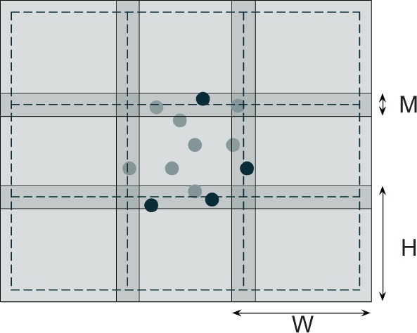
Overlapping of substacks (depicted in 2D for simplicity). Processing is carried out in the region of size W × H but detected cells are only accepted if their centers fall within the region of size (delimited by dashed lines). Sample accepted and rejected cells after processing the central substack are shown as light and dark circles, respectively
2.2.2 Cell identification
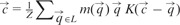
Clustering is an extremely common segmentation approach in low-level computer vision and image processing. Typically in these applications the goal is to group together pixels sharing similar features or colors. Here we propose a different strategy aiming at grouping together voxels belonging to the same soma. Our algorithm outputs cluster centroids that (ideally) correspond to soma centers. Because the number of clusters is clearly unknown in our case (because it corresponds to the number of cells), we take a non-parametric approach with a variant of mean shift (Comaniciu and Meer, 2002). The algorithm takes as input two sets of points, L and S, where each point is represented by a triplet of 3D coordinates. L is the set of voxels whose intensity exceeds the background threshold as explained in Section 2.2.3. The classic mean shift algorithm would start from all available data points, place a kernel on each of them and shift each point toward the mean value computed as the kernel-weighted average of the data. In our variant, we improve both its running time and its statistical precision by starting from a carefully chosen set of seeds S (see Section 2.2.4). Pseudo-code of our variant is listed below.
1
2 for each
3
4 repeat
5
6 until converged
7
8 return
In the above code, m is a function returning the intensity of a voxel and K the kernel function. In practice we use a spherical kernel:
where R is a parameter that should be smaller than the expected radius of a cell. The normalization factor Z in line 5 is defined as  so that gets assigned to the ‘center of mass’ of points falling within the sphere defined by the kernel function. We use KD-trees (Bentley, 1975) to retrieve this set of points. The function in line 8 removes near-duplicates from C.
2.2.3 Thresholding
The overall running time of the clustering algorithm presented in Section 2.2.2 is dominated by time required to answer ball queries to the KD-tree, which grows at least as . For this reason, the image is thresholded to get rid of dark voxels, which are unlikely to be part of a soma. Thresholding also helps to limit the number of false-positive detections.
We used a multi-threshold version of the maximum entropy approach of (Kapur et al., 1985). We set three ranges of voxel intensities and computed by maximum entropy the two delimiting thresholds θ1 and θ2. The first range was regarded as background, i.e. dark areas, which we assumed to contain no detectable soma. The two other ranges were retained as foreground.
2.2.4 Seeding
The set of seeds S is determined as follows. First, we extract all local maxima of the image using a 3D max-filter. Second, we perform a 3D convolution of the image with a normalized spherical filter of size r. Seeds are then all local maxima such that the corresponding value in the convolved image is above the binarization threshold θ1 determined in Section 2.2.3. In other words, we require that the average voxel intensity in the ball or radius r centered on a local maximum be above θ1.
2.3 Supervised semantic deconvolution
The clustering procedure described above yields good results (details in Section 3.2) on image regions where cell somata have high and uniform intensity and the contrast on dendritic trunks is modest. Other regions are more problematic: if the thresholding and seed selection is too strict, faintly visible somata disappear during the preparation of sets S and L, leading to false-negative detections; if too loose, then many non-soma regions (such as dendritic arbors or axonal bundles) are retained and FPs arise. To improve over this intrinsic difficulty, we carried out a preprocessing stage by applying a non-linear filter trained to boost weak somata and decrease the voxel intensities in non-soma regions. This step was carried out in a supervised fashion because we believe that the FPs versus false negatives (FNs) trade-off can only be properly addressed by introducing human knowledge. The goal of semantic deconvolution is not to undo the blurring or degradation effects associated with the image acquisition process (as in classic deconvolution) but rather to enhance and standardize the visibility of specific entities of interest in the image (somata in our case). We trained a neural network to map the original image into an ‘ideal’ image, which is entirely black except for small white spheres positioned at the locations of the true cell somata. In Figure 2 we illustrate the concept on a small image portion. In order to smooth the neural network targets far away from the somata centers, we actually generated the ideal image by first setting the intensity of the central voxel to the maximum value and then applying a (non-normalized) 3D Gaussian filter with , truncated at .
Fig. 2.
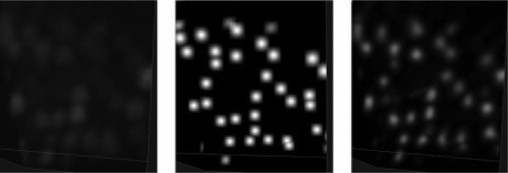
Illustration of semantic deconvolution: a portion of the original image (left), the associated ideal image (middle), image filtered by the trained neural network (right). Best viewed by zooming in a computer screen
We reserved 10 labeled substacks to build a training set. Note that our approach does not require us to perform a precise segmentation of cell somata: markers at the locations of the true centers (see Section 3.1.1 for details of the ground-truth preparation procedure) are sufficient. As a consequence, the human effort required to carefully annotate in this way the 10 training substacks (0.11% of a whole cerebellum image, 1770 cells in total) was modest (∼3 h of work).
The use of neural networks as non-linear convolutional filters for 3D images has been proposed before in (Jain et al., 2007) where the goal was to recover human drawn cell boundaries in electron microscopy images at much higher (20 nm) resolution. In our case, the 10 training substacks would total 194 MVoxel, ∼400 times the training set used in (Jain et al., 2007). Additionally, the resulting training set would be highly unbalanced because, in our images, the vast majority of voxels fall in dark regions. Therefore, rather than performing a full convolution, we sampled ∼2 million training patches ensuring that half of them (‘positive’ patches) overlapped with locations of cell centers and the remaining half (‘negative’ patches) were at least 30 voxels away from the centers and had an average gray level above 10. The neural network was trained on small cubic patches of size . In our experiments we used s = 6, yielding patches of 2197 voxels. The goal is to predict, for each voxel, the conditional probability that it falls in a white area of the original image. A naive approach would be to use a neural network with inputs and one single output (corresponding to the central voxel). However, this approach would have at least two disadvantages. First, nearby output voxels are correlated, and predicting them independently is not the best choice from a statistical point of view. Second, filtering a whole volume of size n (assumed to be cubic for simplicity) would require time . Instead, we used a neural network with outputs. In this way, several adjacent voxels are predicted simultaneously, sharing the same feature maps as in a multi-task learning problem (Caruana, 1997). The semantically deconvolved image R is then obtained as
| (1) |
where (x, y, z) is the generic output voxel, Z is a normalization factor and denotes the 3D patch produced in output by the neural network when the input is the 3D patch of the original image centered at coordinates (a, b, c). In this formulation, each output voxel is actually obtained by averaging several predictions, which helps to reduce the variance component of the generalization error. Using 3D output patches is also advantageous from a computational point of view. First, note that the running time of a network with output is still (in facts it just takes twice the time of a network with a single output). Second, rather than moving the patch by one voxel, we may move the patch by skipping d voxels along each dimension. In this way, the overall running time is reduced to . In our experiments, we used d =4 with a speedup of ∼32 with respect to the naive approach. This is significant because filtering 120GVoxels takes over a day on a Xeon E5-2665 computer with 16 physical cores, and using the naive approach would require more than a month. Note that when using a stride of length d, the normalization factor Z in Equation 1 actually depends on the test point (x, y, z) because not all output voxels are obtained by averaging the same number of predictions.
We used a network with two fully connected hidden layers: 2197 inputs, 500 and 200, units in the hidden layers, and 2197 outputs (∼1.6 million parameters in total). Preliminary experiments with a third layer did not yield appreciable improvements. We used sigmoidal output units, which allow us to interpret each output as the conditional probability that a certain voxel belongs to a cell soma given the original image patch as input. Similarly to (Hinton et al., 2006), we pretrained the first two layers in an unsupervised fashion (as Gaussian–binary and binary–binary restricted Boltzmann machines, respectively). Some of the filters learned by the first layer of the network are shown in Supplementary Figure S4. Fine-tuning of the overall network was finally performed by backpropagation, training for ∼100 epochs of stochastic gradient descent with momentum and with a minibatch size of 10. Altogether, training took slightly <2 days on 16 cores. Semantic deconvolution was performed on substacks of size to ensure that the cell identification subroutines (see Section 2.2) receive data with no border effects.
2.4 Manifold modeling
The procedure described in this section takes advantage of specific anatomical background knowledge. In several brain regions, such as in the cerebellum, cells are not scattered randomly in the 3D space but are laid out in manifolds. For example, the cerebellum cortex folds into folia or leaves that can be naturally modeled as manifolds. As it turns out, isolated or off-manifold centers predicted by the algorithms described above are almost invariably false-positive detections. Hence, an effective false-positive filter may be designed by estimating the distance of each predicted center from the manifold formed by other predicted centers. Our approach exploits manifold learning [specifically, the Isomap algorithm (Tenenbaum et al., 2000)] and locally weighted regression (Cleveland, 1979) to obtain such an estimate.
Because Isomap needs to compute the eigendecomposition of the estimated geodesic distance matrix from the nearest-neighbors graph, it cannot be applied to large set of points. Thus, we begin by partitioning predicted centers into smaller subsets. The approach is inspired by a computer graphics technique known as chartification (Zhou et al., 2004). Chartification algorithms, however, are typically designed to work on meshes rather than point clouds and they are not robust enough to handle the noisy detections that occur in our application. We used instead the following procedure. First, we obtained a set of seeds by computing the centroid of detections within each substack in which the overall image was divided (see Section 2.2.1). Second, starting from each seed, we formed a chart by running a uniform cost search on the nearest neighbors graph with edges weighted by Euclidean distances, proceeding until a predefined geodesic distance from the seed was reached. Charts obtained in this way may overlap but this is fine because our goal is ultimately to detect FPs. Manifold distances on each chart are estimated using the following algorithm:
// is a set of predicted centers
1
2 for
3 Let
4
5 return
In the above code, the procedure takes as input the predicted centers and returns their 2D embeddings obtained by first computing the nearest neighbors graph to obtain estimated geodesic distances and then performing multidimensional scaling [see (Tenenbaum et al., 2000) for details]. The procedure learns a locally weighted regression model from the 2D coordinates (u, v) back to the 3D coordinates (x, y, z). is a lazy learner, which simply stores the training data and at prediction time performs weighted linear regression. For the sake of completeness we briefly summarize the method here. Given the left-out test point , we first form the matrix , whose j-th row is and where the real-valued weights are given by the Gaussian kernel
| (2) |
We then form the matrix whose j-th row is . computes its prediction as
| (3) |
To reduce the influence of outliers, we finally used the iterative reweighting approach described in (Cleveland, 1979). Intuitively, reconstructs the 3D coordinates of the i-th center given the other centers in the chart. If the i-th center is far from the manifold, then we expect the Euclidean distance (see Line 4 in the above algorithm) between the true and reconstructed coordinates to be high, yielding a sensible criterion for filtering out false-positive detections. As noted above, our charts may overlap, meaning that multiple distance values are estimated whenever a center appears in multiple charts. In these cases, we eventually retained the minimum estimated manifold distance. The quality of Isomap embeddings is sensitive to outliers; we thus found it beneficial to run the manifold filter iteratively, first with a high distance threshold of 40 voxels, to get rid of gross false-positive detections, and a second time with a smaller threshold to perform a finer grained filtering.
3 RESULTS AND DISCUSSION
3.1 Performance evaluation
3.1.1 Ground truth
To estimate the accuracy of the cell detection algorithm we annotated soma centers in 56 substacks of a cerebellum image, each of size , for 4,138 markers and 1.09 GVoxel (10 additional disjoint substacks were marked for training the semantic deconvolution network described in Section 2.3). Each ground truth substack included exactly eight adjacent processing substacks. The set of ground truth substacks was chosen to cover different cerebellum regions and to ensure that the contrast variability in the whole image was well represented. Some nearly empty regions were also included to better estimate the false-positive rate. Cell centers were located with the help of a modified version of the Vaa3D software package (Peng et al., 2010). In our version, the one-right-click pinpointing procedure takes advantage of the 3D mean shift algorithm described in Section 2.2 but applies it to a cylinder whose main axis is defined by the line connecting the observer point and the clicked point. Using a fairly small cylinder radius (∼6–8 voxels) and rotating the 3D view of the image to avoid overlaps, the cylinder will almost always contain just one soma and a reliable marker can be assigned in just a few seconds. The 3D mean shift algorithm also ensures that the marker identifies the soma center with good accuracy. Still, the high variability in image quality makes hand labeling non-trivial. We found that two independent human labelings on nine substacks disagree on 40 markers of 957.
3.1.2 Measuring performance
For each substack, we compare the set of cluster centers C returned by the clustering procedure, and the set of ground truth centers G. To properly compare predictions against the ground truth we need to ensure that each predicted soma center is uniquely associated with at most one ground truth center. For this purpose, we first construct an undirected bipartite graph with vertex set . For each pair and we add an edge with weight if , being D the expected diameter of a Purkinje soma (we set D = 16 in our experiments) and є a small constant preventing numerical overflows. We then compute the maximum weight bipartite matching. A predicted center is considered to be a true positive (TP) if it is matched to a ground truth center such that . Unmatched predictions are counted as FPs and unmatched ground truth centers are counted as FNs. We finally compute precision, recall and F1 measure as and . To avoid the bias due to border effects, we take advantage of the overlapping between substacks (Fig. 1) and exclude from the TP, FP or FN counts all points (either predictions or ground truth) falling in the outer region of thickness .
3.2 Mean shift clustering on the raw image
We ran the algorithm of Section 2.2 on the raw image, with different values of the parameters r (radius of the seed ball) and R (radius of the kernel). As expected, the algorithm achieves its best performance when both parameters are set to a value that roughly corresponds to the radius of the smallest somata in the image (Fig. 4). Too low values for r generate too many seeds, increasing the chances of false-positive detections. Precision is also sensitive to the kernel radius because small values of R tend to generate multiple detections within the same true soma. The slight increase of FNs when increasing R can be explained as follows: when two somata are close to each other and almost touch, a large kernel drives the algorithm to converge near the border between the two somas. When setting r = 6 and R = 5.5, the cell detector on raw images attains a precision of 0.76 and a recall of 0.71, corresponding to 920 FPs and 1213 FNs.
Fig. 4.

Comparing performance of the mean shift algorithm before and after semantic deconvolution and varying the parameters r (seed radius ball) and R (kernel size). Left: performance when varying r and fixing R = 6. Right: performance when varying R and fixing r = 6
3.3 Using semantic deconvolution
The performance of the mean shift algorithm increases dramatically when applied to the image cleaned by the semantic deconvolution technique described in Section 2.3. Setting r = 6 and R = 5.5 yields 493 FPs and just 120 FNs, corresponding to a precision of 0.89, a recall of 0.97 and an F1-measure of 0.93. As shown in Figure 4, the algorithm is also much less sensitive to the choice of R. If r is too small with respect to the expected soma radius, many FPs arise. This is because the neural network may hallucinate small non-soma light regions as soma (one example occurs in the leftmost region of the central substack shown in Fig. 3). Increasing r beyond six continues to improve precision at the expense of recall, but keeping the F1-measure almost constant.
3.4 Using the manifold filter
We finally evaluated the effect of the manifold modeling technique described in Section 2.4. We first computed the estimated manifold distances and filtered all predictions with . This step removed some FPs without losing any significant recall. We then applied reestimated manifold distances on the remaining predictions and computed a recall–precision curve when varying the manifold distance threshold. Starting from the set of cells detected with r = 6 and R = 5.5, we obtained the curve shown in Figure 5. The area under this curve is 0.97. As expected, precision decreases with the distance threshold, while recall increases. Still, it is possible to reduce significantly the number of FPs without sacrificing recall. Any threshold between 11 and 27 voxels keeps the F1-measure >0.96. The sensitivity of the overall method with respect to r and R is further reduced after the manifold filter: any value of r and R between 5 and 7 yields an F1-measure >0.95 if using a distance threshold of 20. With the application of the manifold filter (with threshold 20), the algorithm detected 224 222 Purkinje cells in the whole cerebellum image (Fig. 6). This number is consistent with previous estimates based on stereology (Biamonte et al., 2009; Woodruff-Pak, 2006).
Fig. 5.

Effects of the manifold distance filter. Left: recall–precision curve. Right: performance measures as a function of the distance threshold
Fig. 6.
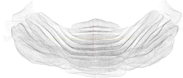
The final set of predicted Purkinje cell centers as a point cloud
3.5 Discussion
Quantitative histological measurements are typically restricted to small portions of tissue. In fact, on the one hand, conventional microscopy techniques are unable to generate large-scale volumetric datasets (Osten and Margrie, 2013). On the other hand, currently available algorithms for cell segmentation or localization usually require carefully tuned parameters and therefore cannot cope with the image variability that may be present in large-scale datasets. The only well-established quantitative method to investigate cytoarchitecture on a brain-wide scale is stereology (Schmitz and Hof, 2005), which, however, provides only estimates of the number of cells, without a precise map of their spatial distribution. Furthermore, stereological estimates rely on a priori assumptions about the imaged tissue, which make the final result dependent on the starting hypothesis (Schmitz and Hof, 2005).
Here, we presented an algorithm for fully automatic detection of neuronal soma in CLSM fluorescence images, in which human supervision is needed only for the initial training of a neural network. After training on a small sample of substacks, the neural network is able to generalize well on different brain regions. This suggests that the network trained on one cell type and one brain will be able to perform semantic deconvolution equally well for the same cell type of other brains within a uniform population of animals. The robustness of the method when applied to heterogeneous samples should be further investigated. In particular, it might be necessary to collect larger and more representative datasets if one wants to detect cells with different sizes/shapes or in comparative studies involving animals with anatomical variations or disease models. In our experience, the overall work devoted to labeling was modest compared with the work devoted to sample preparation and image acquisition.
The capabilities of this algorithm have been demonstrated by localizing all the Purkinje neurons in a whole mouse cerebellum. The algorithm is robust against the contrast variability in different image regions. The sensitivity of performance with respect to the mean shift kernel radius and the manifold filter distance is modest (Figs 4 and 5) and the seed selection parameter r can be chosen according to the expected size of visible soma. One possible future extension to improve our quantitative results is to associate a confidence score or a probability to each detection.
Our method obtains the best results when the manifold filter is used. This can be a limitation, as the cellular subset under investigation might be scattered in all the three dimensions, without any apparent uniformity in the spatial distribution. Further, even if neurons lie on a manifold in physiological conditions, this regularity might disappear (at least partly) in presence of a pathology. Thus, if one wants to compare healthy and unhealthy subjects, a manifold-independent localization pipeline could provide more reliable results. Anyhow, the modeling of the manifold can be useful also in this case, allowing a quantitative description of the spatial scattering of neurons.
The combination of the method presented here with genetically targeted expression of fluorescent proteins, or with whole-brain immunohistochemistry (Chung et al., 2013), will allow precisely localizing and counting selected neuronal populations throughout the entire encephalon, eventually leading to a set of brain-wide cytoarchitectonic maps of the various cell types.
4 CONCLUSION
We presented an automated pipeline for the localization of neuronal soma in large-scale images obtained with CLSM. The method has been validated on images of the cerebellum of an L7-GFP mouse. We found that semantic deconvolution significantly boosted performance at a modest cost in terms of hand labeling. We obtained an F1 value of 0.96. While some margin for improvement may remain, human labeling disagreement suggests that F1 values >0.98 are unlikely to be attainable. We further demonstrate the algorithm by producing the full map of Purkinje cells in the whole mouse cerebellum.
Supplementary Material
ACKNOWLEDGMENTS
We would like to thank Pietro Pala for useful discussions.
Funding: The work of L.S. and F.P. was supported by E.U. grants FP7 228334, FP7 284464 and FET flagship HBP (604102).
Conflict of Interest: none declared.
REFERENCES
- Becker K, et al. Chemical clearing and dehydration of GFP expressing mouse brains. PLoS One. 2012;7:e33916. doi: 10.1371/journal.pone.0033916. [DOI] [PMC free article] [PubMed] [Google Scholar]
- Bentley JL. Multidimensional binary search trees used for associative searching. Commun. ACM. 1975;18:509–517. [Google Scholar]
- Biamonte F, et al. Interactions between neuroactive steroids and reelin haploinsufficiency in Purkinje cell survival. Neurobiol. Dis. 2009;36:103–115. doi: 10.1016/j.nbd.2009.07.001. [DOI] [PubMed] [Google Scholar]
- Bohland JW, et al. A proposal for a coordinated effort for the determination of brainwide neuroanatomical connectivity in model organisms at a mesoscopic scale. PLoS Comput. Biol. 2009;5:e1000334. doi: 10.1371/journal.pcbi.1000334. [DOI] [PMC free article] [PubMed] [Google Scholar]
- Bria A, Iannello G. Terastitcher-a tool for fast automatic 3d-stitching of teravoxel-sized microscopy images. BMC Bioinformatics. 2012;13:316. doi: 10.1186/1471-2105-13-316. [DOI] [PMC free article] [PubMed] [Google Scholar]
- Briggman KL, Bock DD. Volume electron microscopy for neuronal circuit reconstruction. Curr. Opin. Neurobiol. 2011;22:154–161. doi: 10.1016/j.conb.2011.10.022. [DOI] [PubMed] [Google Scholar]
- Briggman KL, et al. Wiring specificity in the direction-selectivity circuit of the retina. Nature. 2011;471:183–188. doi: 10.1038/nature09818. [DOI] [PubMed] [Google Scholar]
- Buggenthin F, et al. An automatic method for robust and fast cell detection in bright field images from high-throughput microscopy. BMC Bioinformatics. 2013;14:297. doi: 10.1186/1471-2105-14-297. [DOI] [PMC free article] [PubMed] [Google Scholar]
- Caruana R. Multitask learning. Mach. Learn. 1997;28:41–75. [Google Scholar]
- Chung K, et al. Structural and molecular interrogation of intact biological systems. Nature. 2013;497:332–337. doi: 10.1038/nature12107. [DOI] [PMC free article] [PubMed] [Google Scholar]
- Cleveland WS. Robust locally weighted regression and smoothing scatterplots. J. Am. Stat. Assoc. 1979;74:829–836. [Google Scholar]
- Comaniciu D, Meer P. Mean shift: a robust approach toward feature space analysis. IEEET Pattern Anal. 2002;24:603–619. [Google Scholar]
- Dodt H-U, et al. Ultramicroscopy: three-dimensional visualization of neuronal networks in the whole mouse brain. Nat. Methods. 2007;4:331–336. doi: 10.1038/nmeth1036. [DOI] [PubMed] [Google Scholar]
- Forero MG, et al. Deadeasy Mito-Glia: Automatic counting of mitotic cells and glial cells in Drosophila. PLoS One. 2010;5:e10557. doi: 10.1371/journal.pone.0010557. [DOI] [PMC free article] [PubMed] [Google Scholar]
- Gong H, et al. Continuously tracing brain-wide long-distance axonal projections in mice at a one-micron voxel resolution. NeuroImage. 2013;74:87–98. doi: 10.1016/j.neuroimage.2013.02.005. [DOI] [PubMed] [Google Scholar]
- Goodfellow IJ, et al. 2013 doi: 10.1109/TPAMI.2012.273. Pylearn2: a machine learning research library arXiv preprint arXiv:1308.4214. [DOI] [PubMed] [Google Scholar]
- Helmstaedter M, et al. High-accuracy neurite reconstruction for high-throughput neuroanatomy. Nat. Neurosci. 2011;14:1081–1088. doi: 10.1038/nn.2868. [DOI] [PubMed] [Google Scholar]
- Hinton GE, et al. A fast learning algorithm for deep belief nets. Neural Comput. 2006;18:1527–1554. doi: 10.1162/neco.2006.18.7.1527. [DOI] [PubMed] [Google Scholar]
- Jain V, et al. Proceedings of the 11th International Conference on Computer Vision (ICCV) IEEE Piscataway; 2007. Supervised learning of image restoration with convolutional networks; pp. 1–8. [Google Scholar]
- Kapur J, et al. A new method for gray-level picture thresholding using the entropy of the histogram. Comput. Vis., Graph. Image Process. 1985;29:273–285. [Google Scholar]
- Kasthuri N, Lichtman JW. The rise of the ‘projectome’. Nat. Methods. 2007;4:307–308. doi: 10.1038/nmeth0407-307. [DOI] [PubMed] [Google Scholar]
- Keller PJ, Dodt H-U. Light sheet microscopy of living or cleared specimens. Curr. Opin. Neurobiol. 2012;22:138–143. doi: 10.1016/j.conb.2011.08.003. [DOI] [PubMed] [Google Scholar]
- Kleinfeld D, et al. Large-scale automated histology in the pursuit of connectomes. J. Neurosci. 2011;31:16125–16138. doi: 10.1523/JNEUROSCI.4077-11.2011. [DOI] [PMC free article] [PubMed] [Google Scholar]
- Knott G, et al. Serial section scanning electron microscopy of adult brain tissue using focused ion beam milling. J. Neurosci. 2008;28:2959–2964. doi: 10.1523/JNEUROSCI.3189-07.2008. [DOI] [PMC free article] [PubMed] [Google Scholar]
- LaTorre A, et al. 3D segmentations of neuronal nuclei from confocal microscope image stacks. Front. Neuroanat. 2013;7:49. doi: 10.3389/fnana.2013.00049. [DOI] [PMC free article] [PubMed] [Google Scholar]
- Li A, et al. Micro-optical sectioning tomography to obtain a high-resolution atlas of the mouse brain. Science. 2010;330:1404–1408. doi: 10.1126/science.1191776. [DOI] [PubMed] [Google Scholar]
- Lichtman JW, Denk W. The big and the small: challenges of imaging the brain’s circuits. Science. 2011;334:618–623. doi: 10.1126/science.1209168. [DOI] [PubMed] [Google Scholar]
- Mayerich D, et al. Knife-edge scanning microscopy for imaging and reconstruction of three-dimensional anatomical structures of the mouse brain. J. Microsc. 2008;231:134–143. doi: 10.1111/j.1365-2818.2008.02024.x. [DOI] [PubMed] [Google Scholar]
- Navlakha S, et al. Unsupervised segmentation of noisy electron microscopy images using salient watersheds and region merging. BMC Bioinformatics. 2013;14:294. doi: 10.1186/1471-2105-14-294. [DOI] [PMC free article] [PubMed] [Google Scholar]
- Oh SW, et al. A mesoscale connectome of the mouse brain. Nature. 2014;508:207–214. doi: 10.1038/nature13186. [DOI] [PMC free article] [PubMed] [Google Scholar]
- Osten P, Margrie TW. Mapping brain circuitry with a light microscope. Nat. Methods. 2013;10:515–523. doi: 10.1038/nmeth.2477. [DOI] [PMC free article] [PubMed] [Google Scholar]
- Pedregosa F, et al. Scikit-learn: machine learning in python. J. Mach. Learn. Res. 2011;12:2825–2830. [Google Scholar]
- Peng H, et al. V3D enables real-time 3D visualization and quantitative analysis of large-scale biological image data sets. Nat. Biotechnol. 2010;28:348–353. doi: 10.1038/nbt.1612. [DOI] [PMC free article] [PubMed] [Google Scholar]
- Peng H, et al. Extensible visualization and analysis for multidimensional images using Vaa3D. Nat. Protoc. 2014;9:193–208. doi: 10.1038/nprot.2014.011. [DOI] [PubMed] [Google Scholar]
- Quan T, et al. NeuroGPS: automated localization of neurons for brain circuits using L1 minimization model. Sci. Rep. 2013;3:1414. doi: 10.1038/srep01414. [DOI] [PMC free article] [PubMed] [Google Scholar]
- Ragan T, et al. Serial two-photon tomography for automated ex vivo mouse brain imaging. Nat. Methods. 2012;9:255–258. doi: 10.1038/nmeth.1854. [DOI] [PMC free article] [PubMed] [Google Scholar]
- Sahoo PK, et al. A survey of thresholding techniques. Comput. Vis., Graph Image Process. 1988;41:233–260. [Google Scholar]
- Schmitz C, Hof P. Design-based stereology in neuroscience. Neuroscience. 2005;130:813–831. doi: 10.1016/j.neuroscience.2004.08.050. [DOI] [PubMed] [Google Scholar]
- Silvestri L, et al. Confocal light sheet microscopy: micron-scale neuroanatomy of the entire mouse brain. Opt. Express. 2012;20:20582–20598. doi: 10.1364/OE.20.020582. [DOI] [PubMed] [Google Scholar]
- Sporns O, et al. The human connectome: a structural description of the human brain. PLoS Comput. Biol. 2005;1:e42. doi: 10.1371/journal.pcbi.0010042. [DOI] [PMC free article] [PubMed] [Google Scholar]
- Tenenbaum JB, et al. A global geometric framework for nonlinear dimensionality reduction. Science. 2000;290:2319–2323. doi: 10.1126/science.290.5500.2319. [DOI] [PubMed] [Google Scholar]
- Tomomura M, et al. Purification of Purkinje cells by fluorescence-activated cell sorting from transgenic mice that express green fluorescent protein. Eur. J. Neurosci. 2001;14:57–63. doi: 10.1046/j.0953-816x.2001.01624.x. [DOI] [PubMed] [Google Scholar]
- Woodruff-Pak D. Stereological estimation of Purkinje neuron number in C57BL/6 mice and its relation to associative learning. Neuroscience. 2006;141:233–243. doi: 10.1016/j.neuroscience.2006.03.070. [DOI] [PubMed] [Google Scholar]
- Zhou K, et al. Proceedings of the Eurographics/ACM SIGGRAPH symposium on Geometry processing. ACM, New York: 2004. Iso-charts: stretch-driven mesh parameterization using spectral analysis; pp. 45–54. [Google Scholar]
Associated Data
This section collects any data citations, data availability statements, or supplementary materials included in this article.