Abstract
In this paper, we demonstrate 3-D photoacoustic imaging (PAI) of light absorbing objects embedded as deep as 5 cm inside strong optically scattering phantoms using a miniaturized (4 mm × 4 mm × 500 µm), 2-D capacitive micromachined ultrasonic transducer (CMUT) array of 16 × 16 elements with a center frequency of 5.5 MHz. Two-dimensional tomographic images and 3-D volumetric images of the objects placed at different depths are presented. In addition, we studied the sensitivity of CMUT-based PAI to the concentration of indocyanine green dye at 5 cm depth inside the phantom. Under optimized experimental conditions, the objects at 5 cm depth can be imaged with SNR of about 35 dB and a spatial resolution of approximately 500 µm. Results demonstrate that CMUTs with integrated front-end amplifier circuits are an attractive choice for achieving relatively high depth sensitivity for PAI.
Index Terms: Capacitive micromachined ultrasound transducer (CMUT) array, deep tissue imaging, optoacoustic, photoacoustic
Introduction
Photoacoustic imaging (PAI) is a nonionizing hybrid medical imaging modality that has found wide applications in recent years [1]–[7]. The basic principle of PAI is described next. First, a nanosecond pulsed-laser light illuminates the target tissue. Then, the target tissue exhibits transient thermoelastic expansion and emits broadband ultrasound waves, when the light is absorbed by chromophores (such as oxy- and deoxyhemoglobin, melanin, and water) within the tissue. Lastly, like in conventional ultrasound imaging, the propagating ultrasound waves are detected by an acoustic transducer that is coupled to the tissue using an acoustic coupling medium such as water, ultrasound gel, or oil. Simple image reconstruction algorithms are then used to generate 3-D volumetric photoacoustic images. The main advantage of PAI is that it generates rich optical contrast images of deep tissue at ultrasound resolution, which is typically 1/100th of an imaging depth in diffusion regime. This infers that at 5 cm imaging depth, a spatial resolution of 500 µm can be obtained. At selected wavelengths, the differential optical absorption due to endogenous chromophores, oxy- and deoxyhemoglobin, can provide functional information of biological tissues [1]. To further improve sensitivity and specificity, functionalized molecular imaging agents such as absorbing dyes, fluorescent molecules [for example, indocyanine green (ICG)], gold nanoparticles, carbon nanotubes, and smart activatable agents can be administered intravenously to allow for imaging of molecular targets [8], [9]. Since ultrasound and PAI share the same detection platform, several studies have demonstrated performing PAI using a commercial ultrasound machine that has a linear array ultrasound probe integrated with an optical fiber bundle [3], [10]. Therefore, PAI can complement conventional ultrasound imaging in both preclinical small animal imaging studies and several clinical applications such as breast/prostate cancer diagnosis.
However, one of the main challenges of PAI is the limited depth penetration due to strong scattering of light as it propagates through biological tissues [11]. Therefore, the amount of light energy that can reach absorbers deep inside the tissue is relatively limited. This translates into a very weak ultrasound signal. It is very important to overcome this difficulty as applications such as breast cancer and prostate cancer diagnosis desire a penetration depth as great as 5 cm or in some cases even higher. While increasing the incident laser energy can boost the generated ultrasound signal, the maximum allowable laser energy is restricted due to potential injury to the tissue (e.g., burns) [12]. This necessitates a different approach. One potential approach is to use very high sensitive ultrasound detectors to detect weak acoustic signals coming from deeper regions of tissues. In addition, endoscopy applications such as transrectal and transvaginal applications demand a miniaturized ultrasound device that has high depth sensitivity in photoacoustic mode.
In this paper, we demonstrate that a miniaturized (4 mm × 4 mm × 500 µm) 2-D capacitive micromachined ultrasonic transducer (CMUT) array of 16 × 16 elements with a center frequency of 5.5 MHz is capable of imaging optical absorbers embedded as deep as 5 cm inside chicken breast tissue and optically scattering phantoms. This is possible because of the reduced noise floor and high sensitivity, by having the preamp circuit flip chip bonded to the CMUT directly. The miniature size of CMUT and IC allows one to optimally route light-delivering optical fibers around the flip chip bonded device, and thereby effectively integrates light and ultrasound components to meet strict dimensional requirements of several endoscopy devices. This opens tremendous opportunities (including in the field of interventional molecular imaging) for early diagnosis of different cancer types while taking advantage of the unique high resolution and depth of penetration of photoacoustic molecular imaging.
II. Methods
A. Two-Dimensional CMUT Array With Integrated Electronics
The very small size of transducer elements used in 2-D ultrasound arrays (with center frequencies in the megahertz range) necessitates the tight integration of electronic circuits, especially the preamplifiers, to improve the SNR. For the prototype used in this study, a 2-D CMUT array is flip chip bonded to a custom-designed application-specific IC (ASIC) comprising a dedicated pulser and preamplifier for each element of the array [13]. Compared to piezoelectric transducers, CMUTs can be more conveniently integrated with front-end electronic circuits (either monolithically or using a multichip approach) as both the electronics and the transducer are manufactured using standard silicon fabrication techniques. The 2-D CMUT array used in this study was fabricated using a sacrificial layer etch process [13]–[15]. Key parameters of this CMUT array are shown in Table I.
TABLE I.
CMUT Array Parameters
| Number of cells per element | 24 |
| Cell diameter | 36 µm |
| Element pitch | 250 µm |
| Membrane thickness | 0.6 µm |
| Cavity thickness | 0.1 µm |
| Insulating layer thickness | 0.15 µm |
| Silicon substrate thickness | 400 µm |
| Flip-chip bond pad diameter | 50 µm |
| Through-wafer interconnect diameter | 20 µm |
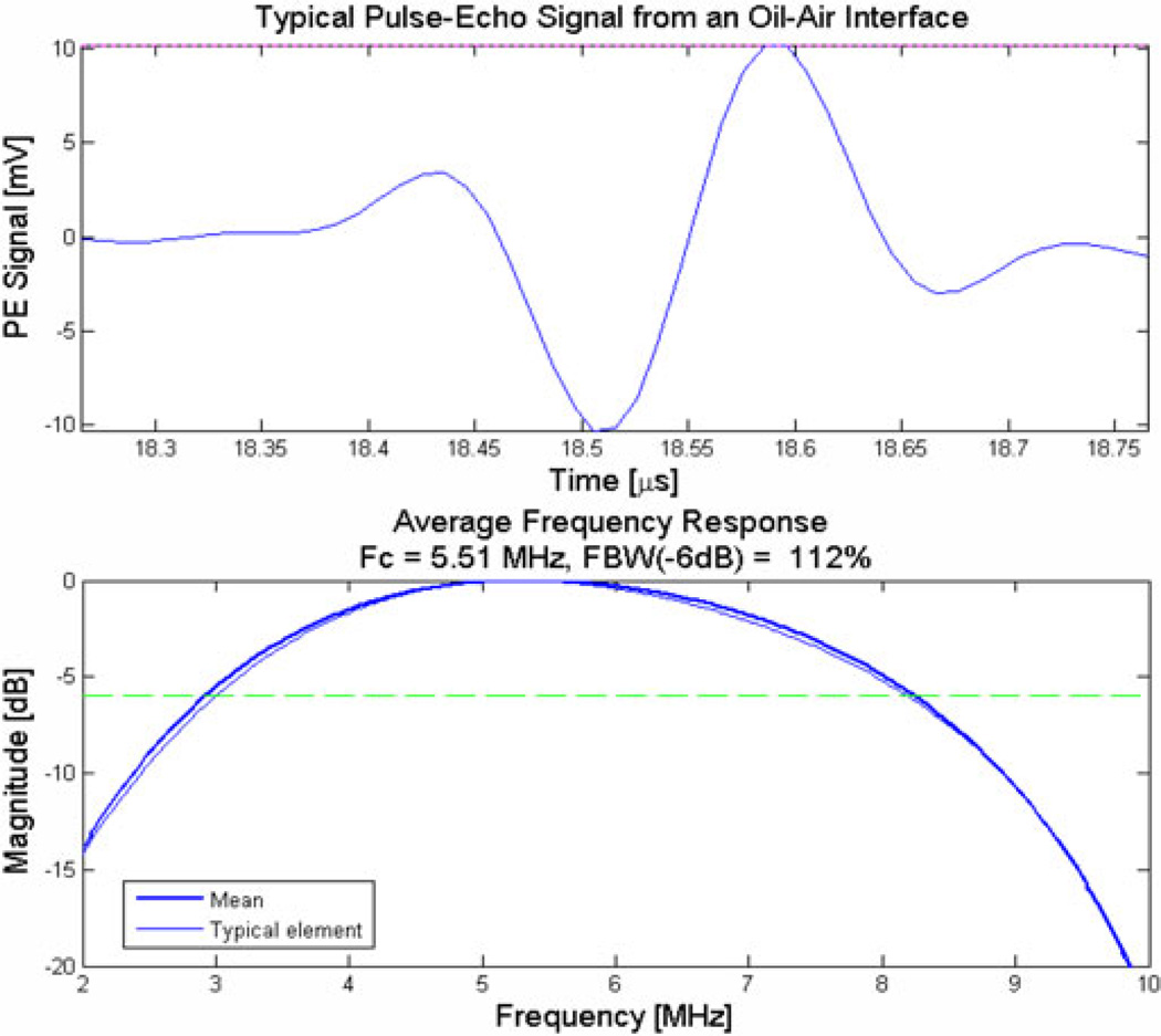
It has 256 elements (16 × 16) and all elements are functional. Pulse-echo characterization from an oil–air interface showed that this CMUT has a center frequency of 5.5 MHz and a fractional bandwidth of above 100% (see Fig. 1).
Fig. 1.
Typical impulse response from one of the elements of the 2-D CMUT array.
The ASIC underneath the CMUT has the circuitry for transmitting pulses and the preamps for amplifying receiving signals. The design and characterization details of the pulser and preamplifier present in the ASIC are reported in [13]. Having the IC flip chip bonded directly to the CMUT improves SNR by two primary means: 1) it alleviates the parasitic cable capacitance, and 2) it reduces the generated noise by using a shorter electrical transmission path. It is demonstrated that a 2-D CMUT array of 250 µm × 250 µm element (of area 6.25 × 10⁻² mm2) used in this study can achieve minimum detectable pressure of 1.1 mPa/ √ Hz, a value close to the theoretical detection limit (thermal noise floor) of 0.9 mPa/ √ Hz. In comparison, Beard et al. reported that for a polyvinylidene fluoride (PVDF) transducer of area 3.14 × 10⁻² mm2, it can achieve minimum detectable pressure of 424.3 mPa/ √ Hz, a value much larger than the theoretical detection limit (thermal noise floor) of 0.89 mPa/ √ Hz [16]. The ratio of the detected and theoretical values for the CMUT and PVDF transducers translates to noise figure of 1.75 and 53.6 dB, respectively. The ASIC used in this paper allows only one CMUT element to transmit or receive at a time. Therefore, it takes at least 256 laser pulses to acquire an image frame. The feasibility of photoacoustic and ultrasound imaging using different varieties of CMUT arrays has been demonstrated earlier [17]–[19]. ASICs with a greater number of parallel receiving channels have been developed that enable real-time imaging with proper back-end hardware [13].
B. Experimental Setup
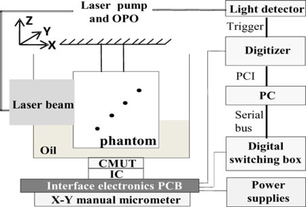
As shown in Fig. 2, the laser light from a tunable optical parametric oscillator pumped by a Q-switched Nd:YAG laser (Model SLIII-10, Continuum, Santa Clara, CA) is delivered along the X-axis to the imaging phantom with a free-space optical setup. The laser pulses have a pulse width of 6 ns and a repetition rate of 10 Hz. For this experiment, the laser wavelength was set at 800 nm and the laser power was measured to be 15.4 mJ/cm2. This power is ~25% below the American National Standards Institute (ANSI) safety limit for human skin exposure of 20 mJ/cm2 [12]. The laser beam size when it enters the imaging phantom holder has a diameter of approximately 2.54 cm.
Fig. 2.
Schematic photoacoustic experimental setup. Laser beam is delivered along the X-axis with a free-space optics setup. The CMUT along with interface electronics is fixed to X–Y micrometer for manual scanning. CMUT array is looking forward along the +Z-axis. The phantom holder was suspended stationary inside an oil tank and dots represent horse hair pieces placed diagonally (with respect to both light and ultrasound positions) at different depths inside the phantom.
It is important to note that optically absorbing objects (for example, black hair strands or ICG-dyed objects) were diagonally placed in the phantom made of either chicken tissue or intralipid–gelatin mixture. This is to simulate reflection geometry where for each object the light source and ultrasound detector are equally distant. For example, for the horse hair strand embedded at 5 cm depth, it means that the light has to propagate a minimum distance of about 5 cminside chicken breast tissue before it reaches the absorber. The generated photoacoustic signal at 5 cm depth has to propagate back through the chicken breast tissue before it is detected by an element in the CMUT array placed below the phantom (as shown in Fig. 2). In a reflection geometry setup, however, the light source and the ultrasound detector are on the same side with respect to the phantom or subject under investigation.
The CMUT along with the printed circuit board interface electronics is fixed to the X–Y scanning stage for raster scanning 16 × 16 element CMUT array along X and Y directions. The raster scanning allowed us to perform array tiling, whereby a 64 × 64 element array is simulated, to illustrate the advantages of larger arrays [19]. At each X and Y positions, photoacoustic A-scan signals are captured by all 256 elements of the CMUT array, but one element at a time. For each element, the photoacoustic signal is averaged 4 times. The signals are subsequently digitized by an 8-bit digitizer (Model PCI-5114, National Instruments, Austin, TX) and stored on a PC for offline processing.
C. Image Reconstruction
The images are reconstructed with a synthetic aperture focusing technique. The A-scans are first bandpass filtered (2–25 MHz) before appropriately delayed and summed. Then the image is processed with coherence factor weighing. The coherence factor estimates the signal coherence quality by a weighting between zero and one. Therefore, it corrects the focusing error due to sound velocity inhomogeneities by multiplying the noncoherent signal with a low weighting [20].
III. Results and Discussion
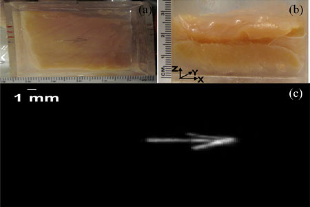
Using 2-D CMUT arrays, we previously demonstrated that ultrasound imaging and PAI provide complementary contrast of various phantom objects [19]. For many practical biomedical imaging applications (e.g., prostate imaging), it is desirable to image biological tissues of thicknesses beyond 10 mm in reflection geometry. While ultrasound imaging is known to provide deep tissue imaging beyond 10 cm, PAI is limited by strong scattering of light in biological tissue. Therefore, in this paper, we focused on deep tissue PAI using reflection mode geometry. As shown in Fig. 3, we performed initial studies on a 25-mmthick chicken breast tissue phantom. Fig. 3(a) shows optical picture (top view) of an open phantom where three horse black hair pieces (100 µm diameter each, creating an arrow shape) are placed about 2 cm deep (with respect to both light and ultrasound propagation directions) inside the chicken breast tissue. Fig. 3(b) shows the side view of the phantom. Fig. 3(c) shows the reconstructed volumetric photoacoustic image with SNR of about 45 dB.
Fig. 3.
Photoacoustic imaging of a 2.5-cm-thick chicken breast tissue phantom. (a) Open (top view) picture of an arrow-shaped object made of three horse black hair pieces (diameter of each hair piece is about 100 µm) placed about 2 cm deep inside the chicken breast tissue phantom. (b) Side view of the phantom. As shown in Fig. 2, light is delivered on the left side of the phantom, along the X-axis, with a free-space optics setup and the CMUT array is looking forward along the +Z-axis. (c) Reconstructed volumetric photoacoustic image of the phantom.
To further study the deep tissue PAI capabilities of the CMUT array and understand how spatial resolution and SNR depend on the depth, we built a 7 cm × 7 cm × 7 cm thick chicken breast tissue phantom. We chose chicken breast tissue because the effective attenuation coefficient in chicken breast muscle is similar to that in some human breast tissue. At 5 cm maximum imaging depth, the attenuation is about 6 times the 1/e optical penetration depth, corresponding to 26-dB attenuation [11].
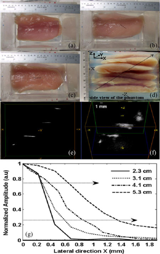
Fig. 4(a)–(c) shows open phantom (top view) pictures of three horse black hair pieces kept at 3.1, 4.1, and 5.3 cm inside the phantom, respectively. The fourth hair piece kept at 2.2 cm (not shown) is similar to the one in Fig. 4(b) but in a diagonally opposite direction. The side view of the 5.3 cm chicken breast tissue phantom made up of several tissue slices and gelatin gel is shown in Fig. 4(d). Gelatin gel is used as a matrix to fix the slices in the phantom holder. Fig. 4(e) and (f) shows different volumetric views of the reconstructed 3-D photoacoustic data. While Fig. 4(e) represents the side view, Fig. 4(f) represents the skewed top view of the reconstructed volume. The orientations of all four objects in these figures are in agreement with actual placement of objects inside the phantom. The dependence of spatial resolution and SNR on depth of all four objects (2.2, 3.1, 4.1, and 5.3 cm) is tabulated in Table II.
Fig. 4.
Deep tissue photoacoustic imaging of four horse hair objects placed 2.2, 3.1, 4.1, and 5.3 cm deep inside the chicken breast tissue phantom. (a)–(c) show objects with different orientations placed 3.1, 4.1, and 5.3 cm deep inside the chicken breast tissue phantom, respectively. (d) Side view of the phantom. The diagonal arrow indicates the direction of the objects being placed inside the phantom with respect light (−X) and CMUT array (−Z) positions. (e) and (f) are different volumetric views of the reconstructed photoacoustic image. (g) ESF of all objects.
TABLE II.
Spatial Resolution and SNR as a Function of Depth
| Object depth (cm) |
Lateral resolution (µm) |
Axial resolution (µm) |
SNR (dB) |
|
|---|---|---|---|---|
| FWHM | ESF | FWHM | ||
| 2.2 cm | 720 ± 2.5 | 240 | 350 ± 1.5 | 36 |
| 3.1 cm | 1080 ± 2.8 | 330 | 300 ± 3.2 | 40 |
| 4.1 cm | 1152 ± 3.9 | 490 | 330 ± 1.8 | 31 |
| 5.3 cm | 1573 ± 3.9 | 720 | 370 ± 5.6 | 23 |
Like in conventional ultrasound imaging, the lateral resolution of PAI in diffusion regime (more than a few millimeter depth) depends on transducer focusing capabilities (such as focal length, aperture diameter, and center wavelength of the transducer), while the axial resolution depends on the bandwidth and center frequency of the transducer. We calculated the lateral resolution based on full width at half maximum (FWHM) of the object and also based on the edge spread function (ESF) of the object. Point spread function, which is the response of an imaging system to a point impulse, often underestimates spatial resolution when the impulse is no longer a delta function in either spatial or time domain. This is very true in the case of optical imaging (and also PAI) where light pulses are strongly scattered by the thick biological tissue medium. Under these conditions, the ESF becomes useful [21]. Fig. 4(g) shows typical lateral ESFs of objects at four different depths, 2.2, 3.1, 4.1, and 5.3 cm. We calculated lateral resolution as the one-way distance between the 25% and 75% points, as marked by dashed arrows in the Fig. 4(g) of the respective ESFs.
However, we calculate axial resolution of the object based on the mean of FWHM of several A-lines passing through the object. As reported in the literature before, this calculation yields similar results as numerical shift and sum technique. In this experiment, we are limited to one position of light irradiance (unlike reflection geometry where light and detector both move from one data point/object to another), which is centered on the object placed at 4.1 cm depth inside the phantom. As mentioned previously, the light spot size is ~2.5 cm. Unlike the experiment in Fig. 3, since the light is not optimally irradiating the 2.2 cm object, the SNR at 2.2 cm depth is not better than the corresponding values of the objects at other depths. To overcome this problem and further optimize our experimental setup for deep tissue imaging, we intend to improve the geometry in future by incorporating the light ring around the CMUT array so that both light and CMUT are scanned together. Our calculations show that the object at 5.3 cm depth has SNR of 23 dB and the best lateral and axial resolutions of 720 and 370 µm, respectively. These values are in accordance with theoretical calculations based on the CMUT array parameters. The SNR can be further improved with better light geometry and averaging. It is possible to image beyond 5 cm depth inside a soft biological tissue (such as breast and prostate) by optimizing several imaging parameters such as choosing optical wavelength of greater than 900 nm, increasing the optical fluence to respective ANSI safety limit [11], and using engineered nanoparticles/small molecule dyes that have many-fold higher optical absorption than intrinsic optical absorption in tissue transparent window.
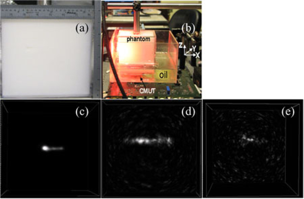
As a last step, we studied photoacoustic sensitivity of the CMUT array for different concentrations of ICG placed 5 cm deep inside an optically scattering phantom. The phantom is prepared by mixing 10 wt% porcine gelatin (Sigma G2500) and 1 wt% intralipid (Fresenius Kabi) in distilled water and molding a slab of dimensions 7 cm × 7 cm× 7 cm. The reduced scattering coefficient and absorption coefficient of the phantom are µ′s = 8 cm−1 and µa = 0.1 cm−1 for a laser wavelength of 775 nm. The side view and experimental setup of the phantom with respect to light and CMUT array are shown in Fig. 5(a) and (b), respectively. Fig. 5(c)–(e) shows volumetric images of 10 µM, 1 µM, and 100 nM concentrations of ICG tubes (polyethylene tubing with 0.38 mm inner diameter and 1.09 mm outer diameter, Intramedic, Becton Dickinson, NJ) with an SNR of 37, 21, and 13 dB, respectively. The axial and lateral resolutions of the 10 µMconcentration tube are calculated to be 360 and 520 µm, respectively.
Fig. 5.
ICG sensitivity study at 5 cm depth inside an optically scattering phantom made of intralipid–gelatin mixture. The optical reduced scattering and absorption coefficients of the background are µ′s = 8 cm−1 and µa = 0.1 cm−1, respectively. (a) Side view of the phantom. (b) Experimental setup of the phantom with respect to light and CMUT array. (c)–(e) show volumetric photoacoustic images of 0.38 mm inner diameter polyethylene tube, filled with ICG concentrations of 10 µM, 1 µM, and 100 nM, respectively, placed 5 cm deep inside the phantom with respect to both light and CMUT array positions.
IV. CONCLUSION
We have demonstrated that a 2-D CMUT array with a center frequency of 5.5 MHz is capable of imaging optically absorbing objects embedded as deep as 5 cm inside a chicken tissue phantom and an optically scattering phantom. The lateral resolution and axial resolution at 5 cm depth is approximately 360 and 500 µm, respectively. Better axial resolution is evident from the fact that CMUT array has a fractional bandwidth of above 100%. A minimum ICG concentration of 100 nM is detected at 5 cm depth inside an optically scattering phantom with 13 dB SNR. These experiments demonstrate that high depth sensitivity of CMUT array is possible by having the ASIC flip chip bonded to the CMUT directly. The close proximity of the front-end electronics to the CMUT mitigates the parasitic capacitance and improves the noise performance. Other advantages of the 2-D CMUT array include 3-D imaging capability and its miniature size. The miniature size is an important feature for endoscopic applications. In summary, the CMUT array has proved to be a promising candidate for deep PAI applications that requires further evaluation in patients.
Acknowledgment
Dr. Kothapalli would like to thank Hamalainen Pelican Postdoctoral Fellowship from The Sir Peter and Lady Michael Foundation. National Semiconductor provided the fabrication of the ICs. CMUT fabrication is done at the Stanford Nanofabrication Facility (Stanford, CA), which is a member of National Nanotechnology Infrastructure Network.
This work was supported in part by the Canary Foundation, and in part by the National Cancer Institute (NCI) In Vivo Cellular and Molecular Imaging Center under Grant P50 CA114747 (SSG), and NCI Center for Cancer Nanotechnology Excellence and Translation under Grant U54CA151459. The ICs and 2-D capacitive micromachined ultrasonic transducer (CMUT) arrays were made using NIH grants CA 99059 and CA 134720 (Khuri-Yakub). Canon, Inc., also partially supported photoacoustic imaging with CMUTS.
Footnotes
Color versions of one or more of the figures in this paper are available online at http://ieeexplore.ieee.org.
Contributor Information
Sri-Rajasekhar Kothapalli, Email: ksraj@stanford.edu, Molecular Imaging Program, Department of Radiology and Bio-X Program, Stanford University, Palo Alto, CA 94035 USA.
Te-Jen Ma, Email: tejenma@gmail.com, Department of Electrical Engineering, Stanford University, Palo Alto, CA 94305 USA.
Srikant Vaithilingam, Email: srikantv@stanford.edu, Department of Electrical Engineering, Stanford University, Palo Alto, CA 94305 USA.
Ömer Oralkan, Email: omer.oralkan@ncsu.edu, Edward L. Ginzton Laboratory, Stanford University, Stanford, CA 94305 USA.
Butrus T. Khuri-Yakub, Email: khuri-yakub@stanford.edu, Department of Electrical Engineering, Stanford University, Palo Alto, CA 94305 USA.
Sanjiv Sam Gambhir, Email: sgambhir@stanford.edu, Departments of Radiology, Bioengineering, and Materials Science and Engineering, and also with Molecular Imaging Program, Department of Radiology and Bio-X Program, Stanford University, Palo Alto, CA 94305 USA.
References
- 1.Wang LV. Multiscale photoacoustic microscopy and computed tomography. Nat. Photon. 2009;3:503–509. doi: 10.1038/nphoton.2009.157. [DOI] [PMC free article] [PubMed] [Google Scholar]
- 2.Razansky D, Distel M, Vinegoni C, Ma R, Perrimon NN, Köster RW, Ntziachristos V. Multispectral opto-acoustic tomography of deep-seated fluorescent proteins in vivo. Nat. Photon. 2009;3:412–417. [Google Scholar]
- 3.Mohammad AY, Sergey AE, Hans-Peter B, Richard S, André C, Matthew F, Brent BA, Massoud M, Oraevsky AA. Optoacoustic imaging of the prostate: Development toward image-guided biopsy. J. Biomed. Opt. 2010;15 doi: 10.1117/1.3333548. 021310-(1–8) [DOI] [PMC free article] [PubMed] [Google Scholar]
- 4.Karpiouk AB, Wang B, Emelianov SY. Development of a catheter for combined intravascular ultrasound and photoacoustic imaging. Rev. Sci. Instrum. 2010;81:014901:1–014901:7. doi: 10.1063/1.3274197. [DOI] [PMC free article] [PubMed] [Google Scholar]
- 5.Kruger RA, Lam RB, Reinecke DR, Rio SPD, Doyle RP. Photoacoustic angiography of breast. Med. Phys. 2010;37:6096–6100. doi: 10.1118/1.3497677. [DOI] [PMC free article] [PubMed] [Google Scholar]
- 6.Piras D, Wenfeng X, Steenbergen W, van Leeuwen TG, Manohar SG. Photoacoustic imaging of the breast using the twente photoacoustic mammoscope: Present status and future perspectives. IEEE J. Sel. Topics Quant. Elect. 2010 Jul-Aug;16(4):730–739. [Google Scholar]
- 7.Zhang EZ, Laufer JG, Pedley RB, Beard PC. In vivo high-resolution 3D photoacoustic imaging of superficial vascular anatomy. Phy. Med. Biol. 2009;54:1035–1046. doi: 10.1088/0031-9155/54/4/014. [DOI] [PubMed] [Google Scholar]
- 8.De La Zerda A, Zavaleta C, Keren S, Vaithilingam S, Bodapati S, Liu Z, Levi J, Smith BR, Ma TJ, Oralkan O, Cheng Z, Chen X, Dai H, Khuri-Yakub BT, Gambhir SS. Carbon nanotubes as photoacoustic molecular imaging agents in living mice. Nat. Nanotechnol. 2008;3:557–562. doi: 10.1038/nnano.2008.231. [DOI] [PMC free article] [PubMed] [Google Scholar]
- 9.Levi J, Kothapalli S-R, Ma TJ, Hartman K, Khuri-Yakub BT, Gambhir SS. Design, synthesis, and imaging of an activatable photoacoustic probe. J. Am. Chem. Soc. 2010;132:11264–11269. doi: 10.1021/ja104000a. [DOI] [PMC free article] [PubMed] [Google Scholar]
- 10.Kim C, Erpelding TN, Jankovic L, Pashley MD, Wang LV. Deeply penetrating in vivo photoacoustic imaging using a clinical ultrasound array system. Biomed. Opt. Exp. 2010;1:278–284. doi: 10.1364/BOE.1.000278. [DOI] [PMC free article] [PubMed] [Google Scholar]
- 11.Ku G, Wang LV. Deeply penetrating photoacoustic tomography in biological tissues enhanced with an optical contrast agent. Opt. Lett. 2005;30:507–509. doi: 10.1364/ol.30.000507. [DOI] [PubMed] [Google Scholar]
- 12.American National Standard for Safe Use of Lasers. Orlando, FL: Laser Institute of America; 2000. ANSI Z136 1-2000. [Google Scholar]
- 13.Wygant I, Zhuang X, Yeh D, Oralkan O, Ergun AS, Karaman M, Khuri-Yakub BT. Integration of 2D CMUT arrays with front-end electronics for volumetric ultrasound imaging. IEEE Trans. Ultrason., Ferroelectr. Freq. Cont. 2008 Feb;55(2):327–342. doi: 10.1109/TUFFC.2008.652. [DOI] [PubMed] [Google Scholar]
- 14.Jin X, Ladabaum I, Khuri-Yakub BT. The microfabrication of capacitive ultrasonic transducers. J. Microelectromech. Syst. 1998;7:295–302. [Google Scholar]
- 15.Ergun AS, Huang Y, Zhuang X, Oralkan O, Yaralioglu GG, Khuri-Yakub BT. Capacitive micromachined ultrasonic transducers: Fabrication technology. IEEE Trans. Ultrason. Ferroelectr. Freq. Control. 2005 Dec;52(12):2242–2258. doi: 10.1109/tuffc.2005.1563267. [DOI] [PubMed] [Google Scholar]
- 16.Beard PC, Hurrell AM, Mills TN. Characterization of a polymer film optical fiber hydrophone for use in the range 1 to 20 MHz: A comparison with PVDF needle and membrane hydrophones. IEEE Trans. Ultrason., Ferroelectr. Freq. Cont. 2000 Jan;47(1):256–264. doi: 10.1109/58.818769. [DOI] [PubMed] [Google Scholar]
- 17.Oralkan O, Ergun AS, Johnson JA, Karaman M, Demirci U, Kaviani K, Lee TH, Khuri-Yakub BT. Capacitive micromachined ultrasonic transducers: Next-generation arrays for acoustic imaging. IEEE Ultrason., Ferroelectr., Freq. Contr. Soc. 2002 Nov;49(11):1596–1610. doi: 10.1109/tuffc.2002.1049742. [DOI] [PubMed] [Google Scholar]
- 18.Nikoozadeh A, Wygant IO, Lin D, Oralkan O, Ergun AS, Stephens DN, Thomenius KE, Dentinger AM, Wildes D, Akopyan G, Shivkumar K, Mahajan A, Sahn DJ, Khuri-Yakub BT. Forward-looking intracardiac ultrasound imaging using a 1-D CMUT array integrated with custom front-end electronics. IEEE Trans. Ultrason., Ferroelectr. Freq. Cont. 2008 Dec;55(12):2651–2660. doi: 10.1109/TUFFC.2008.980. [DOI] [PMC free article] [PubMed] [Google Scholar]
- 19.Vaithilingam S, Ma T-J, Furukawa Y, Wygant IO, Zhuang X, de la Zerda A, Oralkan O, Kamaya A, Gambhir SS, Jeffrey JRB, Khuri-Yakub BT. Three-dimensional photoacoustic imaging using a two-dimensional CMUT array. IEEE Trans. Ultrason., Ferroelectr. Freq. Cont. 2009 Nov;56(11):2411–2419. doi: 10.1109/TUFFc.2009.1329. [DOI] [PubMed] [Google Scholar]
- 20.Liao C-K, Li M-L, Li P-C. Optoacoustic imaging with synthetic aperture focusing and coherence weighting. Opt. Lett. 2004;29:2506–2508. doi: 10.1364/ol.29.002506. [DOI] [PubMed] [Google Scholar]
- 21.Bushberg JT, Seiber JA, Leidholdt EM, Boone JM. The Essential Physics of Medical Imaging. 2nd ed. Philadelphia, PA: Lippincott Williams & Wilkins; 2002. pp. 267–269. [Google Scholar]


