

Abstract
Cryopreservation protocols are increasingly required in regenerative medicine applications but must deliver functional products at clinical scale and comply with Good Manufacturing Process (GMP). While GMP cryopreservation is achievable on a small scale using a Stirling cryocooler-based controlled rate freezer (CRF) (EF600), successful large-scale GMP cryopreservation is more challenging due to heat transfer issues and control of ice nucleation, both complex events that impact success. We have developed a large-scale cryocooler-based CRF (VIA Freeze) that can process larger volumes and have evaluated it using alginate-encapsulated liver cell (HepG2) spheroids (ELS). It is anticipated that ELS will comprise the cellular component of a bioartificial liver and will be required in volumes of ∼2 L for clinical use. Sample temperatures and Stirling cryocooler power consumption was recorded throughout cooling runs for both small (500 μL) and large (200 mL) volume samples. ELS recoveries were assessed using viability (FDA/PI staining with image analysis), cell number (nuclei count), and function (protein secretion), along with cryoscanning electron microscopy and freeze substitution techniques to identify possible injury mechanisms. Slow cooling profiles were successfully applied to samples in both the EF600 and the VIA Freeze, and a number of cooling and warming profiles were evaluated. An optimized cooling protocol with a nonlinear cooling profile from ice nucleation to −60°C was implemented in both the EF600 and VIA Freeze. In the VIA Freeze the nucleation of ice is detected by the control software, allowing both noninvasive detection of the nucleation event for quality control purposes and the potential to modify the cooling profile following ice nucleation in an active manner. When processing 200 mL of ELS in the VIA Freeze—viabilities at 93.4%±7.4%, viable cell numbers at 14.3±1.7 million nuclei/mL alginate, and protein secretion at 10.5±1.7 μg/mL/24 h were obtained which, compared well with control ELS (viability −98.1%±0.9%; viable cell numbers −18.3±1.0 million nuclei/mL alginate; and protein secretion −18.7±1.8 μg/mL/24 h). Large volume GMP cryopreservation of ELS is possible with good functional recovery using the VIA Freeze and may also be applied to other regenerative medicine applications.
Introduction
One bottleneck in manufacturing and clinical delivery of regenerative medicine is successful cryopreservation. The preservation of cells to current Good Manufacturing Process (cGMP) requires validated, reproducible, and safe methods.1 However, cryopreservation provides various challenges in this context. These include retention of good functionality, sterility, and scale up: for example, estimates for a bioartificial liver indicate that cryopreservation of 2 L of alginate-encapsulated cell spheroids (ELS) are required.2
Cryopreservation in bags of large volumes (>100 mL) of adult stem cells3 and of mammalian tissue culture cells4–6 using conventional liquid nitrogen-based controlled rate freezers (CRFs) is established. However, the use of liquid nitrogen is problematic in a GMP environment; following manufacture, liquid nitrogen contains very low levels of contaminants, but during transport and storage it can become contaminated by ice, inanimate debris, and viable microorganisms7–9 that can transfer to the local environment.7,10 It is possible to filter industrial quantities of liquid nitrogen to appropriate standards and the UV sterilization of liquid nitrogen has been proposed11; however, unless liquid nitrogen is filtered or sterilized by validated methods it cannot be used in a clean room without compromising air quality. An alternative strategy, avoiding the requirement for nitrogen during cooling is the use of CRF based on electrically powered Stirling cryocoolers, which operate efficiently down to cryogenic temperatures. Equipment based on Stirling cryocoolers has been successfully used for controlled rate freezing of a range of cell types including human embryonic stem cells and ELS12,13 but this equipment is limited to processing to small volumes (<50 mL total).
In this study, we address the issues of scaling up small volume cryopreservation methods and the development of cryocooler-based equipment for the large volume GMP compatible process. Initially, a set of feasibility experiments was carried out in cryovials applying a range of cooling profiles to investigate the effects of the physical conditions and thermal histories anticipated during cryopreservation in large volumes. We also investigated control of ice nucleation during scale up, which is essential for high cell viability in many cryopreservation protocols.13 We also investigated final cell:cryoprotectant volume ratios, since it is desirable to reduce the overall sample volume as this determines heat transfer both during controlled slow cooling and rapid warming in large volumes.3 Finally, the large-scale Stirling cryocooler-based CRF (VIA Freeze) was used with ELS as a model system for equipment development and optimization.
Materials and Methods
Cell culture
HepG2 cells were obtained from the ECACC (Wiltshire, United Kingdom) and maintained in modified MEM-alpha medium (Gibco, Paisley, United Kingdom) supplemented with 10% FBS (Hyclone, Loughborough, United Kingdom), 100 IU/mL penicillin, and 0.1 mg/mL streptomycin. HepG2 cells were not used beyond passage 50.
The techniques of alginate encapsulation and culture to achieve competent ELS have been described previously. Alginate beads have an approximate diameter of 500 μm. HepG2 cell spheroids are not uniformly spherical but are typically irregular shaped.2,14 For small volume experiments, ELS were maintained in static culture for 7 days in six-well plates in media supplemented with glucose to a final concentration of 22.5 mM, with 10% FFP in place of FCS.2 For large volume experiments, ELS were maintained in culture for 11 days in a fluidized bed bioreactor. Fifty percent, 70%, and 80% media changes were performed on days 6, 8, and 10 respectively.2 For all experiments, cell density within ELS was ∼20×106/mL alginate. The exact cell densities within each set of experiments are given in Tables 1, 2, and 3 under “unfrozen control.” These cell densities represent the standard densities achieved following conditioning culture.
Table 1.
Comparison of ELS Recovery at 24 Hours After Thawing Following Cryopreservation at Different ELS:CPA Ratios
| ELS:CPA ratio (cell density) | Viability (%) | Viable cell number (106 nuclei/mL alginate) | Total function (μg AFP/24 h) | Normalized function (μg AFP/106 nuclei/24 h) |
|---|---|---|---|---|
| Unfrozen control (−) | 98.0±0.5 | 24.9±2.1 | 17.9±0.8 | 23.2±1.7 |
| 1:1 (12.5×10⁶/mL) | 95.9±2.3 | 21.0±2.2 | 11.8±1.1*** | 18.2±2.1* |
| 1:2/3 (15×106/mL) | 95.4±1.4*** | 19.9±2.2* | 11.6±2.6*** | 18.5±3.9 |
| 1:1/3 (18.75×10⁶/mL) | 96.2±1.3 | 17.7±1.3**,# | 11.5±1.4*** | 20.8±2.0 |
| 1:0 (25×106/mL) | 95.3±1.6* | 16.7±1.8**,## | 10.5±1.7***,∼ | 20.2±3.7 |
ELS were cooled in cryovials using the EF600. The rate of cooling was 1°C/min and cholesterol was used as ice nucleant in all samples. Each cryovial contained 250 μL of ELS but the volume of CPA was varied. Four different ratios of ELS:CPA were tested: 1:1 (i.e., 250 μL ELS, 250 μL CPA); 1:2/3; 1:1/3; and 1:0 (e.g., 250 μL ELS, 0 μL CPA). ELS recovery (viability, viable cell numbers, and function) 24 h after thawing was compared to unfrozen control. These data demonstrated that reducing the volume of CPA within the cryovial did not reduce ELS recovery. n=5±SD. *p<0.05, **p<0.01, ***p<0.005 cf. unfrozen control. #p<0.05, ##p<0.01 cf. ELS cryopreserved at an ELS:CPA ratio of 1:1. ∼p<0.05 cf. ELS cryopreserved at an ELS:CPA ratio of 1:1/3.
ELS, encapsulated cell spheroids; CPA, cryoprotectant.
Table 2.
Comparison of ELS Recovery at 24 Hours After Thawing Using Different Warming Rates
| Thawing method | Time taken to thaw (min) | Viability (%) | Viable cell number (106 nuclei/mL alginate) | Function (μg AFP/24 h) |
|---|---|---|---|---|
| Unfrozen control | – | 99.5±0.6 | 17.7±0.9 | 15.3±2.8 |
| 37°C water | 1.75±0.5 | 97.8±0.5*** | 14.4±1.2** | 8.7±1.8* |
| 20°C water | 2.42±0.5 | 93.2±1.7***# | 14.1±0.9** | 7.5±0.3** |
| 20°C air | 12.92±0.2 | 92.7±3.1***,# | 9.3±1.0***,##,∼∼ | 6.5±0.9**,# |
| 4°C air | 24.5±4.7 | 90.9±4.9***,# | 8.3±1.4***,###,∼∼ | 5.8±0.5**,# |
ELS were cooled in cryovials using the EF600. The rate of cooling was 1°C/min and cholesterol was used as ice nucleant in all samples. Following cooling, the cryovials were warmed using four different methodologies: 37°C water; 20°C water; 20°C air; and 4°C water to obtain a range of warming rates. The times taken to thaw the cryovials using these four methodologies is given in column 2 (n=2, mean±range). ELS recovery (viability, viable cell numbers, and function) 24 h after thawing was compared to unfrozen control. These data demonstrate that ELS recovery is greatest when rapid warming rates are applied. n=5±SD. *p<0.05, **p<0.01, ***p<0.005 compared to unfrozen control. #p<0.05, ##p<0.01, ###p<0.005 compared to ELS thawed in 37°C water. ∼∼p<0.01 compared to ELS thawed in 20°C water.
Table 3.
Direct Comparison of ELS Recovery After Cryopreservation Using Three Different Cooling Profiles in Cryovials or Cryobags
| Viability (%) | Viable cell number (106 nuclei/mL alginate) | Function (μg AFP/mL/24 h) | ||
|---|---|---|---|---|
| Unfrozen control | 98.1±0.9 | 18.3±1.0 | 18.7±1.8 | |
| Profile A (Fig. 3) | Cryovial | 82.8±9.8 | 10.6±0.5 | 11.7±4.4 |
| Cryobag | 79.7±13.0 | 10.0±0.6∼∼ | 13.2±1.2^^^ | |
| Profile B (Fig. 3) | Cryovial | 93.4±7.4 | 14.3±1.7 | 10.5±1.7 |
| Cryobag | 85.9±5.5 | 15.2±1.7 | 12.0±0.9^ | |
| Profile C (Fig. 3) | Cryovial | 62.0±10.8 | 6.4±0.5 | 5.7±0.6 |
| Cryobag | 77.2±11.2 | 12.9±1.8***,∼ | 10.2±0.8*** |
ELS were cryopreserved in either cryovials (small volume) or cryobags (large volume) alongside each other. Three different cooling profiles (shown in Fig. 3) were tested. Cholesterol was included as ice nucleant in each and the ELS: CPA ratio was 1:0. ELS recovery (viability, viable cell numbers, and function) 24 h after thawing was compared to unfrozen control. These results indicate that ELS recovery from cryovials and cryobags did not differ when profiles A and B were applied during cooling, suggesting successful scale up of the cryopreservation protocol. n=5±SD. ***p<0.005 compared to ELS cryopreserved in cryovials using the same cooling profile. ∼p<0.05, ∼∼p<0.01 compared to ELS cryopreserved in cryobags using profile B. ^p<0.05, ^^^p<0.005 compared to ELS cryopreserved in cryobags using profile C.
Cryopreservation
Cryoprotectants
ELS were cryopreserved in cryoprotectant (CPA) of 12% DMSO with 10% FFP15 in University of Wisconsin solution with 500 IU/mL catalase and 1.7 mM Trolox as antioxidants15±1 mg/mL crystalline cholesterol to act as a nucleant.16 Unless stated otherwise, the ratio of volumes of ELS to CPA in cryovials was 1:1 representing a cell density of ∼10×106/mL. In some experiments, once alginate beads had been transferred into cryovials and allowed to settle under gravity, the ratios of ELS to CPA were modified by removing supernatant CPA, to achieve ratios of 1:2/3, 1:1/3, and 1:0 (i.e., removal of all supernatant CPA).
Controlled rate freezers
Feasibility experiments in cryovials: For feasibility experiments in small volumes, an EF600 (Grant Instruments, Cambridgeshire, United Kingdom) was used.17 Cryovials (375418; Nunc, Loughborough, United Kingdom) (capacity 1.8 mL) were loaded with 0.25 mL ELS equilibrated with 0.25 mL chilled (4°C) CPA prior to cooling.
Large volume experiments in cryobags: For large volume experiments, a VIA Freeze (Asymptote Ltd, Cambridge, United Kingdom) was used to cryopreserve ELS in cryobags (Fig. 1). In this device, cooling of a horizontal sample plate was achieved by two Stirling cryocoolers connected to a metal plate, directly onto which the cryobags were placed (cooling was achieved from one side of the bag only). The dimensions of the sample plate are 250×450 mm. The plate temperature and the voltage applied to the VIA Freeze were monitored and logged.
FIG. 1.
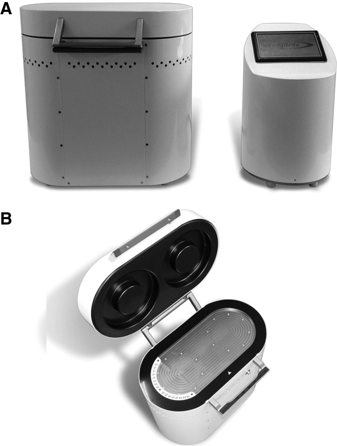
The VIA freeze. The VIA Freeze and controller on the bench top (A), and (B) with lid open showing sample plate and cryovial holder for quality assurance samples (on left-hand plate edge).
For all runs the VIA Freeze was cooled to +4°C and held at this temperature while samples were prepared. ELS were equilibrated with chilled (4°C) CPA and loaded into CryoMACS bags (200-074-404; Miltenyi Biotec Ltd, Glasgow, United Kingdom). Excess CPA was removed by rolling the cryobags so that only ∼10 mL excess CPA remained (with ∼190 mL ELS).
Once loaded onto the VIA Freeze, the plate was held for a further 15 min to allow ELS and plate temperature equilibration before cooling. The cryobags was compressed by a styrofoam lid to achieve a uniform thickness (∼4 mm).
Cooling rates
Outcome assessments of cooling in cryovials for characterization and feasibility experiments: Five cooling profiles were examined in cryovials with ELS containing ∼20×106 cells/mL alginate in the EF600. Three were programmed (Figs. 2A and 3) to characterize ELS recovery using different profiles down to −100°C:
1. A previously studied multi-step slow cooling profile16,18
2. A linear rate of cooling of 1°C/min with a 10-min hold period at −8°C (just below the estimated temperature of ice nucleation in samples with ice nucleants)
3. A linear rate of cooling of 1°C/min
FIG. 2.

Impact of cooling profiles used for feasibility experiments on small volume cryopreservation of encapsulated cell spheroids (ELS). Five different cooling profiles (A) were used to cool ELS in 1.8 mL cryovials to −100°C. These profiles are fully described in the Methods section of this article. The effect of differing ice nucleation temperatures on ELS viability using these profiles in post-thaw cultures was also investigated (B). Cells were cooled by a “multi-step cooling” method (●),16,18 linear 1°C/min (□), linear 1°C/min with an isothermal hold at −8°C (▲), a controlled concentration profile (◊), or a constant change in ice fraction with time (■).19 These data demonstrate that regardless of cooling profile utilized, ELS viability in post-thaw cultures is strongly correlated with ice nucleation temperature. When ice nucleation occurs at higher temperatures (i.e., when cholesterol is present and there is only minimal supercooling), ELS viability in post-thaw cultures is typically high; conversely, if ice nucleation spontaneously occurs at lower temperatures, supercooling will result in poor ELS viability in post-thaw cultures.
FIG. 3.

Cooling profiles used for direct comparison of ELS recovery in small and large volumes. Three different cooling profiles were used to cool ELS in 1.8 mL cryovials using the EF600 and in 200 mL cryobags using the VIA Freeze to −100°C in parallel. A simple linear rate (A) was compared with nonlinear profiles (B, C). In large volumes, heat transfer occurs more slowly as a result of the increased mass. These nonlinear profiles were utilized as these are a more accurate representation of cooling profiles that would be experienced by ELS cooled in large volumes, where heat transfer would be altered compared with ELS cooled in small volumes. They were derived using mathematical modeling.19
Two further profiles (described in detail elsewhere19) designed to model cooling in cryobags were also tested in cryovials using the EF600 (Fig. 2A) These cooling rates applied an average cooling rate of 1°C/min between −8°C and −100°C, with specific but different nonlinear segments in the high subzero temperature range18:
4. “Controlled concentration” profile
5. “Constant change in ice fraction with time” profile
To discern whether or not ice nucleators were necessary during cryopreservation, ELS were cooled in cryovials with either cholesterol (an efficient ice nucleator)16 or with no nucleator.
Cooling profiles used for large volume cryopreservation
Three cooling profiles (shown in Fig. 3) were used in the VIA Freeze and these were replicated in the same experiments in cryovials in the EF600 to directly compare ELS recovery in cryobags to with ELS recovery in cryovials. The first was a linear cooling rate of 1°C/min (identical to profile 3 in Fig. 2A). The second and third profiles used for large volume cryopreservation produced an average rate of cooling of −1°C/min between −8°C and −60°C but were both nonlinear.
Temperature measurements during cooling
T-type thermocouples connected to a Picolog TC-08 data logging device (PicoTechnology, St Neots, United Kingdom) were used to measure the temperatures of samples within bags and cryovials. When the ELS reached programmed end-temperatures, they were transferred to the vapor phase of liquid nitrogen for storage (>1 day).
Warming
Routinely, ELS in either cryovials or bags were removed from storage and transferred to a 37°C water bath until the last ice crystal had melted. Samples were then placed on ice, ELS allowed to settle under gravity, supernatant CPA removed, and washed using equal volumes of chilled culture medium. This was then removed and replaced with complete, prewarmed, culture medium.
To achieve different rates of rewarming in the feasibility studies, cryovials were warmed in +4°C air, +20°C air, or +20°C water. The times taken to thaw (when the last ice crystal melted) from nitrogen storage (−150°C) were recorded.
Ultrastructure of cryopreserved samples
Cryoscanning electron microscopy
Cryovials containing ELS were cooled using a linear cooling rate of −1°C/min in the EF600 and transferred to liquid nitrogen. Cryovials were fractured under liquid nitrogen and the frozen plug removed intact. The plug was fractured vertically down the mid plane under liquid nitrogen and then loaded onto the preparation stage of a FEI Philips XL30 FEGSEM (Quorum PPT 2000). The stage was warmed from −145°C to −95°C over 6 min and the sample etched at −95°C for 60 min before cooling to −145°C. The sample was then coated with 10–15 nm gold and loaded back onto the cryoscanning electron microscopy (CryoSEM) stage for image recording.
Freeze substitution
Some samples were refractured to make segments with a maximum dimension of 1 mm and then transferred under liquid nitrogen to automated freeze substitution chambers (Reichert; Leica, Vienna, Austria). The substitution medium contained 2% osmium tetroxide and 1% uranyl acetate in methyl alcohol as contrast agents. Samples were maintained at −90°C for 24 h, warmed to −70°C at 3°C/h, and then maintained at −70°C for 24 h. Afterward they were warmed to room temperature at +3°C/h, rinsed in methyl alcohol, and embedded in Spurr's epoxy resin. Sections were cut at 0.5 μm thickness with a Reichert Ultracut S and stained with methylene blue for preliminary inspection and orientation.
Cell viability and function following freezing and thawing
For small volume experiments in cryovials in the EF600, ELS were returned to static culture in six-well plates following cryopreservation. For large volume experiments in the Via Freeze, ELS were returned to culture in a rotating cell culture system,14 which mimics the cell culture conditions of the large-scale fluidized bed bioreactor used to culture ELS prior to cryopreservation.
The methods used to assess recovery at 24 h post-warming are described elsewhere.16 (This particular time point post-warming was chosen as this represents the time at which ELS viability would be lowest, before they begin to recover.16) Briefly, ELS were stained using fluorescein diacetate and propidium iodide and viabilities were quantified using image analysis.16 Cell numbers were measured by releasing spheroids from alginate using 16 mM EDTA/0.15 M NaCl (pH 7.4) and nuclei count using the Nucleocounter system. Function was assessed by measuring total α-1-fetoprotein release in the first 24 h post-warming using ELISA.
Statistical analysis
Statistical analyses were performed by one-way ANOVA using Excel software. Each experiment to assess ELS recovery (viability, viable cell numbers, and function) was performed with five replicates and data are presented in Tables 1, 2, and 3 as the mean of these replicates±standard deviation.
Results
Feasibility studies in cryovials
Effect of cooling profile and ice nucleation temperature on ELS recovery
For scale up of the small-volume (0.5 mL) cryopreservation protocols it was necessary to examine the effects of a number of physical variables. Five different cooling profiles were examined (shown in Fig. 2A). ELS were processed, with or without cholesterol as an ice nucleator.
The recovery of ELS viability in post-warming cultures was dependent on the temperature of ice nucleation during cooling (Fig. 2B). When ice nucleation occurred at temperatures below −12°C (in the absence of cholesterol) the recoveries were ∼40%. However, at ice nucleation induced at temperatures >−8°C (in the presence of cholesterol), viability was typically greater than 90% on thawing. Recovery of ELS was most variable following the multi-step cooling protocol. These data suggest that providing efficient ice nucleation occurs, a linear cooling rate of −1°C/min could be used in the large volume freezer and that deviations from linearity, within the range of the two nonlinear profiles examined, would be tolerated.
Ultrastructure in the frozen state
CryoSEM of ELS in samples in which ice had either been nucleated in a controlled manner (using cholesterol, Fig. 4A, C, E) or allowed to occur spontaneously (Fig. 4B, D, F) revealed major differences in the structure of both ice and ELS. Where spontaneous ice nucleation occurred, a uniform fine ice crystal structure (<25 μm diameter) was evident, as etched voids, across the sample (honeycomb structure, Fig. 4D). The outlines of spherical alginate beads are detectable (Fig. 4B, D), and were similar in size to the unfrozen alginate beads (∼500 μm diameter), but any cellular structure was generally masked by the pattern of ice formation. In those instances where cells were apparent (Fig. 4F), ice voids were apparent between cells, but intracellular ice was not evident. In samples with controlled nucleation, alginate beads were indistinguishable (Fig. 4A). ELS were freeze-concentrated into large aggregates (Fig. 4C, E); the individual ELS appeared highly shrunken. Ice crystal voids were adjacent to the cell clusters, and the alginate and extracellular matrix itself appeared to be dehydrated. At higher magnification (Fig. 4E) the outlines of shrunken cells were distinguishable within ELS. Any cellular material appeared granular, while freeze-concentrated alginate and CPA appeared smooth by comparison.
FIG. 4.

Cryoscanning electron microscopy of fractured cryovials after cooling at a linear rate of 1°C/min. Ultrastructure resulting from controlled ice nucleation (A, C, E) is compared to spontaneous ice nucleation (B, D, F). In all samples the spaces originally occupied by ice crystals are revealed as voids following sublimation of ice. In figures (B, D) sectioned alginate beads that are ∼500 μm in diameter are outlined. In (C, E, F), cell clusters (c), ice voids (i), and smooth freeze concentrated alginate and cryoprotectant (CPA) (*) have been labeled. Scale bars on (A, B) 1 mm, on (C, D) 200 μm, and on (E, F) 20 μm.
Freeze substitution of ELS within the induced ice-nucleated sample revealed shrunken cells with densely packed cytoplasm in which it was difficult to differentiate intracellular structures (Fig. 5A). At higher magnification, some cell membrane-like material could be seen but it was difficult to distinguish further. Many clear “shrinkage spaces” were evident. Following spontaneous ice nucleation cells did not appear so shrunken (Fig. 5B) and at higher magnification (Fig. 5D) intracellular organelles, such as mitochondria, were identifiable and there were few “shrinkage spaces.” Intracellular ice was not apparent in any samples, but following spontaneous nucleation intercellular ice had formed within cell clumps.
FIG. 5.

Freeze substitution of fractured cryovials after cooling at a linear rate of 1°C/min. Ultrastructure resulting from controlled ice nucleation (A, C) is compared with spontaneous ice nucleation (B, D). In spontaneously nucleated samples, the spaces originally occupied by ice crystals are revealed as voids following sublimation of ice, and can be seen throughout the ELS structure. These ice voids are absent within cholesterol-nucleated ELS, although there is evidence of shrinkage spaces. At higher magnification, it is difficult to distinguish cell organelles in cholesterol-nucleated ELS due to the extreme cell dehydration during cooling. Conversely, organelles can be seen in spontaneously nucleated ELS. Cellular material (c), ice voids (i), cell membrane (cm), extracellular matrix (ecm), mitochondria (m) shrinkage spaces (s), and alginate (*) have been labeled. Scale bars on (A, B) 2 μm and on (C, D) 500 nm.
Effect of reduced CPA volume on ELS recovery
ELS viability following a linear rate of cooling with cholesterol as ice nucleant was high with no trend toward reduced viability by decreasing the ratio of ELS to CPA, even at the highest cell density (∼30×106/mL). In contrast, lower viable cell numbers and total AFP secretion suggested that decreasing the volume of CPA was detrimental. However, normalized AFP secretion was unaffected by reducing the ELS:CPA ratio (Table 1). These data suggest that CPA volume, after a sufficient equilibration period, may be reduced during large-volume experiments with limited effects on ELS recovery; this simplifies application of large-volume cooling.
Effect of warming conditions on ELS recovery
Following linear cooling at −1°C/min the recovery of ELS in cryovials was adversely affected by the time taken for warming (Table 2). Maximum recoveries were observed following rapid warming although the effect on viability was minor, with viabilities >90% for all thawed ELS at 24 h post-warming.
However, both viable cell numbers and function were more affected by slower warming. Viable cell numbers decreased to 47%, 53%, 79%, and 82% cf. those of unfrozen controls when thawed using 4°C air (p<0.005), 20°C air (p<0.005), 20°C water (p<0.01), and 37°C water (p<0.01) respectively. Similarly, AFP secretion decreased to 37%, 43%, 49% and 57% cf. those of unfrozen controls when thawed using 4°C air (p<0.01), 20°C air (p<0.01), 20°C water (p<0.01) and 37°C water (p<0.05) respectively. These data suggest that rapid warming is crucial to ELS recovery.
Direct comparison of ELS cryopreservation in small volumes in cryovials with large volumes in cryobags
Measurement of cooling profiles using the VIA freeze
Temperature profiles from three different locations in CryoMACS bags containing cell-free alginate beads equilibrated with CPA are presented in Figure 6A and B along with process parameters of the VIA Freeze. Data are shown for a programmed linear cooling rate from +4°C to −100°C.
FIG. 6.

Process parameters and measured temperatures within a CryoMACS bag during linear cooling on the VIA Freeze. (A) The entire cooling run over 1 h 45 min. Set point temperature (solid black line). Measured temperatures within the cryobag containing 200 mL ELS, at the bottom of the bag (dark gray line), in the middle (mid gray line) near to the top (light gray line). Power input (% of maximum electrical power) supplied to the VIA Freeze (dashed black line on right hand Y axis). (B) Detail around ice nucleation in the bags; note expanded X and Y axes: set point temperature (solid black line); measured sample plate temperature (dotted line); power input (% of maximum electrical power) supplied to the VIA Freeze (dashed line on right hand Y axis). Note the plate temperature shows a small inflection in response to the latent heat of ice formation.
The measured temperature of the sample plate closely followed the set point (programme) temperature and was mirrored in a uniform way within the bag until ice nucleation occurred. Following ice nucleation in the presence of cholesterol, at a plate temperature of −7.9°C and a temperature in the fluid at the bottom of the bag of −5.4°C, there was a minor warming of the sample plate. To maintain the programmed cooling profile, a feedback loop increased the electrical power to the VIA Freeze, which then stabilized at a temperature within the range of ice nucleation. When cooling had progressed to ≤−30°C and below throughout the sample, the required power input for the VIA Freeze reduced again to that recorded preice nucleation. Temperature measurements within the bag (Fig. 6) show under-cooling of the region in contact with the cold plate (Fig. 6A, dark gray line) while at the same time the rest of the sample was above the melting point of −4.5°C (Fig. 6A, mid- and light-gray lines). Ice nucleation occurred at the cold wall and heat was extracted as the ice front developed, shown by increased power consumption by the Stirling motors. In this configuration only a small region within the sample in contact with the cold wall was under cooled, and ice propagated through the bulk of sample with no localized under-cooling.
Comparison of ELS recovery following cooling in cryobags using three different cooling profiles
There were no statistically significant differences in viabilities of ELS cryopreserved in cryobags using the three different cooling profiles (Table 3) (p>0.05). However, there were significant differences in viable cell numbers. ELS cryopreserved using Profile B showed significantly improved viable cell numbers in post-thaw culture when compared with ELS cryopreserved using either profile A (p<0.01) and profile C (p<0.05). Furthermore, function of ELS cryopreserved in cryobags using Profile A was significantly improved (p<0.005) cf. ELS cryopreserved using Profile C. Profile B also resulted in significantly improved function cf. Profile C (p<0.05).
Comparison of ELS recovery following cooling in either cryovials or cryobags
Samples were cooled using the profiles described in Figure 3, either in bags on the VIA Freeze or in cryovials on the EF600. The measured time for warming a bag containing 200 mL of alginate beads (cell free) from storage to 0°C in a 37°C water bath was ∼2 min (c.f. 1.75 min in cryovials, Table 2).
ELS recoveries were assessed 24 h post-warming and compared to an unfrozen control at equivalent time point. Using Profiles A or B (Fig. 3), there were no statistically significant differences in recovery (viability, viable cell number, or function) when ELS were cryopreserved in either cryovials or CryoMACS bags (Table 3). However, following Profile C (Fig. 3), ELS recovered from CryoMACS bags displayed greater viable cell numbers (p<0.005) and function (p<0.005) than ELS cryopreserved in cryovials (Table 3).
Discussion
We have previously described that ELS possess many useful synthetic and detoxification functions that could be utilized in the treatment of acute liver failure.2,14–17 Further, we have previously described that it is possible to cryopreserve ELS using both conventional liquid nitrogen and nitrogen-free CRFs.16,17 This work goes beyond this and a cryopreservation protocol developed for small volumes (0.5 mL) was successfully scaled up to large volumes (∼200 mL) in a liquid nitrogen-free CRF, and a number of modifications to the small-scale processes were investigated. The Via Freeze CRF allowed accurate control of the rate of cooling to −100°C, and has potential in processing large volumes of cells within clean room facilities, avoiding the issues associated with the use of liquid nitrogen-based systems. End temperatures of around −90°C are sufficiently close to the glass transition range for this type of CPA mixture (typically around −110°C20) to allow safe transfer below −150°C for storage, supported by the fact that the EF600 technology performed equally well compared with a conventional liquid nitrogen CRF in our previous study.17 Although in this study, samples were stored in the vapor phase of liquid nitrogen, Stirling cryocoolers capable of maintaining temperatures below −150°C exist and could be used to avoid liquid nitrogen entirely during the cryopreservation process.
More importantly, in the context of standard cryopreservation protocols, the data generated during feedback power monitoring of the VIA Freeze may be used to confirm that ice nucleation has been successful as detectable power output is upregulated to compensate for latent heat release following ice nucleation. For example, for cells in bags, the absence of any voltage spikes at temperatures below a plate temperature of −12°C would indicate that ice nucleation had been successful and that the sample viability should be high on warming. However, if a power-input spike was observed at lower plate temperatures, then controlled ice nucleation did not take place and significant undercooling had occurred, predictive of low survival and poor post-warming function. This may be both a valuable tool for future monitoring of cryopreservation protocols for quality control purposes in general, and active control of specific freezing processes allowing automatic cooling profile modification following ice nucleation to achieve beneficial nonlinear profiles.12,19
The multi-step protocol previously used with small volumes16 was not essential; provided that efficient controlled ice nucleation occurred, simplified linear cooling rates were as effective (Table 3). The response of ELS to different ice nucleation temperatures demonstrates that as the extent of undercooling increases, viability post-cryopreservation decreases. CryoSEM and freeze substitution showed that controlled ice nucleation ensures significant cell shrinkage during cooling (Figs. 4 and 5). The intracellular “shrinkage spaces” have been reported elsewhere18 and are probably artefacts associated within efficient chemical fixation of the dehydrated sample (Fig. 5). In ELS that experienced extreme undercooling before ice nucleation occurred, there was little cell shrinkage (Fig. 4B), intracellular ice was not apparent, and the cells exhibited what might be classed as more “normal” morphology. Cellular dehydration occurs in response to the increased extracellular solute concentration that arises during ice formation as solutes are excluded from the ice lattice. During spontaneous ice nucleation, cells are unable to dehydrate, as ice formation is too rapid to allow dehydration within the short time frame. Conversely, during controlled nucleation, ice formation is slower, which enables cells to dehydrate. Following spontaneous ice nucleation, intercellular ice formed (Figs. 4F and 5B). This was not observed in samples in which controlled ice nucleation occurred and may be a stress that results in cell injury. While visually counterintuitive, our data showed that functional recoveries were lower when the ELS were more identifiable as structural entities (Fig. 4B vs. A), which agrees with other studies.21,22 This may reflect the importance of extreme dehydration for successful recovery from the cryopreservation process.
Stochastic ice nucleation during cooling modifies a number of physical processes within the freeze-concentrated matrix and any cells present will experience differing microenvironments. In particular, in samples with controlled ice nucleation the calculated diffusion distance within the freeze concentrated matrix is significantly larger than that following spontaneous ice nucleation.13 Effects on cell dehydration of controlled and spontaneous ice nucleation have previously been confirmed using Fourier transform infrared spectroscopy of mammalian cell lines23,24 and horse spermatozoa25 and it has been shown that cell dehydration is required to avoid lethal intracellular ice formation.
A second aim of this study was to reduce the amount of “excess” CPA volume processed. This is not trivial because, especially at scale up, this largely aqueous mass significantly contributes to the energy required to be removed during controlled cooling, and impacts on the ability to control the temperature profile throughout the entire sample. Similarly during recovery, excess CPA will limit the rate of warming, which is known to influence cell recovery. When ELS were equilibrated with CPA they could be frozen with little excess CPA and retain high viability and function. With ELS, the cell densities, (even with no “excess” CPA) were not high (∼3×10⁷/mL). In past studies, single cell suspensions, cryopreserved at high cell densities (equivalent to low CPA/biomass volume ratios), underwent significant damage, the so-called “cell packing” effect,26,27 but the cell densities were much higher than used here.
As ELS are encapsulated within alginate, it may be expected that the alginate itself offers some protection to the spheroids during cryopreservation. Polymers such as hydroxyl-ethyl starch can contribute toward cryoprotective effects in other systems28 and this has been attributed to increasing the viscosity, and modifying the water-icetransition.29 A similar argument has been proposed for alginate.30 However, in the large majority of cases (including our current work), cell-permeating CPAs are still required. It was clear from freeze-fracture studies (Fig. 4) that ice crystals grew throughout the alginate microspheres, although the control of ice nucleation appeared to result in larger ice crystals. Thus, any cryoprotection afforded by the alginate may result from complex interactions between polymer distribution and the biophysical events of a particular cryopreservation protocol.
Cell losses were observed when ELS of high densities were cryopreserved in small volumes; this could have resulted from handling issues (such as adherence of beads inside tubes or pipettes). However, this was not seen during large-scale cryopreservation in bags.
In this initial study the identified optimal nonlinear profile was similar to that previously employed with cell clusters of human embryonic stem cells.31 In this profile (Fig. 3, Profile B) there is an extended holding period in the temperature zone following ice nucleation, which allows more time for osmotic equilibrium to be established between the cells and the external environment at high subzero temperatures. Ultrastructural studies (Figs. 4 and 5) demonstrated that significant cellular dehydration was protective; thus, osmotic equilibration of the cells with the partially frozen matrix during the extended holding period is one important component of this. However, when using another nonlinear profile (Fig. 3, Profile C), which further extended the period at high subzero temperatures after ice nucleation, a reduced recovery on thawing was observed, suggesting possible cytotoxic effects still occurring at high subzero temperatures. These are likely to contain components of both progressive osmotic injury and CPA toxicity. Further studies are needed to optimize, nonlinear profiles.
The data presented here demonstrate that it is possible to develop cryopreservation protocols in small volume (0.5 mL) samples, which can be scaled up to much larger volumes (200 mL).
A further step in scaling up cryobanking for ELS may require moving from a flexible bag (200 mL ELS) format to a rigid cylindrical cassette (2000 mL ELS). At these large volumes, with a concomitant reduction in the surface area to volume ratio of the sample, modeling suggests that heat transfer properties can significantly vary between different locations within the bulk three-dimensional volume as external cooling is applied32 with potential negative impact on successful cryopreservation. Both cooling and warming profiles will be affected. However, in the cryobag (thin film) format, heat transfer (and therefore cooling and warming rates) will not be significantly compromised compared with those achieved in cryovials, explaining why good results were obtained in both conditions during our current studies.
In translating cell therapies forward to the clinic and implementing essential cryobanking steps, there are several important considerations to achieve compliance with cGMP standards. These will include the selection of an optimized cryopreservation media and CPA mixtures, type and dimensions of containers, use of a liquid nitrogen-free CRF with appropriate methods for controlled ice nucleation, and detection of the nucleation process. All of these have been discussed in relation to the current study.
Acknowledgments
This work was funded by the Technology Strategy Board (project number 130328). The Wellcome Trust enabled fluorescence microscopy studies. We also thank Dr Jeremy Skepper, Department of Anatomy, University of Cambridge for electron microscopy.
Disclosure Statement
I.M., C.S., H.H., B.F., and S.G. declare that no competing financial interests exist. G.J.M. is an employee and director of Asymptote Limited.
References
- 1.Fleck R., and Fuller B.Cell preservation. In: Stacey G.N., and Davis J., eds. Medicines from Animal Cell Culture. Chichester, Sussex, UK: John Wiley & Sons, Ltd, 2007, pp. 417–432 [Google Scholar]
- 2.Erro E., Bundy J., Massie I., Chalmers S.-A., Gautier A., Gerontas S., Hoare M., Sharratt P, Choudhury S., Lubowiecki M., Llewellyn I., Legallais C., Fuller B., Hodgson H., and Selden C.Bioengineering the liver; scale up and cool chain delivery of the liver cell biomass for clinical targeting in a bioartificial liver support system. Biores Open Access 2,1, 2013 [DOI] [PMC free article] [PubMed] [Google Scholar]
- 3.Sputtek A., Rowe A.W., Lioznov M., and Kröger N.Bioequivalence comparison of a new freezing bag (CryoMACS(®)) with the Cryocyte(®) freezing bag for cryogenic storage of human hematopoietic progenitor cells. Cytotherapy 13,481, 2011 [DOI] [PubMed] [Google Scholar]
- 4.Heidemann R., Mered M., Wang D.Q., Gardner B., Zhang C., Michaels J., Henzler H.J., Abbas N., and Konstantinov K.A new seed-train expansion method for recombinant mammalian cell lines. Cytotechnology 38,99, 2002 [DOI] [PMC free article] [PubMed] [Google Scholar]
- 5.Kleman M.I., Oellers K., and Lullau E.Optimal conditions for freezing CHO-S and HEK293-EBNA cell lines: influence of Me2SO, freeze density, and PEI-mediated transfection on revitalization and growth of cells, and expression of recombinant protein. Biotechnol Bioeng 100,911, 2008 [DOI] [PubMed] [Google Scholar]
- 6.Heidemann R., Lnse S., Tran D., and Zhang C.Characterization of cell-banking parameters for the cryopreservation of mammalian cell lines in 100-mL cryobags. Biotechnol Progress 26,1154, 2010 [DOI] [PubMed] [Google Scholar]
- 7.Fountain D., Ralston M., Higgins N., Gorlin J.B., Uhl L., Wheeler C., Antin J.H., Churchill W.H., and Benjamin R.J.Liquid nitrogen freezers: a potential source of microbial contamination of hematopoietic stem cell components. Transfusion 37,585, 1997 [DOI] [PubMed] [Google Scholar]
- 8.Morris G.J.The origin, ultrastructure, and microbiology of the sediment accumulating in liquid nitrogen storage vessels. Cryobiology 50,231, 2005 [DOI] [PubMed] [Google Scholar]
- 9.Bielanski A., and Vajta G.Risk of contamination of germplasm during cryopreservation and cryobanking in IVF units. Hum Reprod 24,2457, 2009 [DOI] [PubMed] [Google Scholar]
- 10.Grout B.W., and Morris G.J.Contaminated liquid nitrogen vapour as a risk factor in pathogen transfer. Theriogenology 71,1079, 2009 [DOI] [PubMed] [Google Scholar]
- 11.Parmegiani L., Accorsi A., Cognigni G.E., Bernardi S., Troilo E., and Filicori M.Sterilization of liquid nitrogen with ultraviolet irradiation for safe vitrification of human oocytes or embryos. Fertil Steril 94,1525, 2010 [DOI] [PubMed] [Google Scholar]
- 12.Morris G.J., Acton E., Faszer K., Franklin A., Yin H., Bodine R., Pareja J., Zaninovic N., and Gosden R.Cryopreservation of murine embryos, human spermatozoa and embryonic stem cells using a liquid nitrogen-free, controlled rate freezer. Reprod Biomed Online 13,421, 2006 [DOI] [PubMed] [Google Scholar]
- 13.Morris G.J., and Acton E.Controlled Ice nucleation in cryopreservation—a review. Cryobiology 66,85, 2013 [DOI] [PubMed] [Google Scholar]
- 14.Coward S.M., Legallais C., David B., Thomas M., Foo Y., Mavri-Damelin D., Hodgson H.J., and Selden C.Alginate-encapsulated HepG2 cells in a fluidized bed bioreactor maintain function in human liver failure plasma. Artif Organs 33,1117, 2009 [DOI] [PubMed] [Google Scholar]
- 15.Massie I., Ross J., Gherardi E., Mallorqui-Fernandez N., Hodgson H., Selden C., and Fuller B.Reducing apoptosis following cryopreservation in encapsulated liver cell spheroids. Abstract presented at the Society for Cryobiology Meeting, Bristol, United Kingdom, 2010. Abstract no. 93. [Google Scholar]
- 16.Massie I., Selden C., Hodgson H., and Fuller B.Cryopreservation of encapsulated liver spheroids for a bioartificial liver: reducing latent cryoinjury using an ice nucleating agent. Tissue Eng Part C Methods 17,765, 2011 [DOI] [PubMed] [Google Scholar]
- 17.Massie I., Selden C., Morris J., Hodgson H., and Fuller B.Cryopreservation of encapsulated liver spheroids using a cryogen-free cooler: high functional recovery using a multi-step cooling profile. Cryoletters 32,158, 2011 [PubMed] [Google Scholar]
- 18.Diener B., Utesch D., Beer N., Drk H., and Oesch F.A method for the cryopreservation of liver parenchymal cells for studies of xenobiotics. Cryobiology 30,116, 1993 [DOI] [PubMed] [Google Scholar]
- 19.Morris G.J., Acton E., and Avery S.A novel approach to sperm cryopreservation. Hum Reprod 14,1013, 1999 [DOI] [PubMed] [Google Scholar]
- 20.Rios J.L.J., and Rabin Y.Thermal expansion of blood vessels in low cryogenic temperatures, Part II: vitrification with VS55, DP6 and 7.05M DMSO. Cryobiology 52,284, 2006 [DOI] [PMC free article] [PubMed] [Google Scholar]
- 21.Walter C.A., Knight S.C., and Farrant J.Ultrastructural appearance of freeze-substituted lymphocytes frozen by interrupting rapid cooling with a period at −26°C. Cryobiology 12,103, 1975 [DOI] [PubMed] [Google Scholar]
- 22.Gosden R.G., Yin H., Bodine R.J., and Morris G.J.Character, distribution and biological implications of ice crystallization in cryopreserved rabbit ovarian tissue revealed by cryo-scanning electron microscopy. Hum Reprod 25,470, 2010 [DOI] [PubMed] [Google Scholar]
- 23.Balasubramanian S.K., Wolkers W.F., and Bischof J.C.Membrane hydration correlates to cellular biophysics during freezing in mammalian cells. Biochim Biophys Acta 1788,945, 2009 [DOI] [PubMed] [Google Scholar]
- 24.Wolkers W.F., Balasubramanian S.K., Ongstad E.L., Zec H.C., and Bischof J.C.Effects of freezing on membranes and proteins in LNCaP prostate tumor cells. Biochim Biophys Acta 1768,728, 2007 [DOI] [PMC free article] [PubMed] [Google Scholar]
- 25.Oldenhof H., Friedel K., Sieme H., Glasmacher B., and Wolkers W.F.Membrane permeability parameters for freezing of stallion sperm as determined by Fourier transform infrared spectroscopy. Cryobiology 61,115, 2010 [DOI] [PubMed] [Google Scholar]
- 26.Pegg D.E., Diaper M.P., Skaer H.L., and Hunt C.J.The effect of cooling rate and warming rate on the packing effect in human erythrocytes frozen and thawed in the presence of 2 M glycerol. Cryobiology 21,491, 1984 [DOI] [PubMed] [Google Scholar]
- 27.De Loecker W., Koptelov V.A., Grischenko V.I., and De Loecker P.Effects of cell concentration on viability and metabolic activity during cryopreservation. Cryobiology 37,103, 1998 [DOI] [PubMed] [Google Scholar]
- 28.Sputtek A.Cryopreservation of red blood cells and platelets. Methods Mol Biol 368,283, 2007 [DOI] [PubMed] [Google Scholar]
- 29.Takahashi T., Hirsh A., Erbe E., and Williams R.J.Mechanism of cryoprotection by extracellular polymeric solutes. Biophys J 54,509, 1988 [DOI] [PMC free article] [PubMed] [Google Scholar]
- 30.Zhang W., Yang G., Zhang A., Xu L., and He X.Preferential vitrification of water in small alginate microcapsules significantly augments cell cryopreservation by vitrification. Biomed Microdevices 12,89, 2010 [DOI] [PubMed] [Google Scholar]
- 31.Morris G.J., Acton E., Collins D., Bos-Mikich A., and de Sousa P.Optimisation of current Good Manufacturing Practice (cGMP) compliant controlled rate freezing for human embryonic stem cells. Cryobiology 61,406, 2010 [Google Scholar]
- 32.Rubinsky B., and Cravalho E.G.An analytical method to evaluate cooling rates during cryopreservation protocols for organs. Cryobiology 21,303, 1984 [DOI] [PubMed] [Google Scholar]