Abstract
To measure and compare the head scatter factor for flattened (FB) and unflattened (FFF) of 6MV and 10MV photon beam using indigenously designed mini phantom. A columnar mini phantom was designed as recommended by AAPM Task Group 74 with low and high atomic number materials at 10 cm (mini phantom) and at approximately twice the depth of maximum dose water equivalent thickness (brass build-up cap). Scatter in the accelerator (Sc) values of 6MV-FFF photon beams are lesser than that of the 6MV-FB photon beams (0.66-2.8%; Clinac iX, 2300CD) and (0.47-1.74%; True beam) for field sizes ranging from 10 × 10 cm2 to 40 × 40 cm2. Sc values of 10MV-FFF photon beams are lesser (0.61-2.19%; True beam) than that of the 10MV-FB photons beams for field sizes ranging from 10 × 10 cm2 to 40 × 40 cm2. The SSD had no influence on head scatter for both flattened and unflattened beams and irrespective of head design of the different linear accelerators. The presence of field shaping device influences the Sc values. The collimator exchange effect reveals that the opening of the upper jaw increases Sc irrespective of FB or FFF photon beams and different linear accelerators, and it is less significant in FFF beams. Sc values of 6MV-FB square field were in good agreement with that of AAPM, TG-74 published data for Varian (Clinac iX, 2300CD) accelerator. Our results confirm that the removal of flattening filter decreases in the head scatter factor compared to flattened beam. This could reduce the out-of-field dose in advanced treatment delivery techniques.
Keywords: Flattening filter, mini phantom, collimator scatter factor
Introduction
All dosimetric systems used in linear accelerator (LINAC) calculations require that dose from photons to a point in a phantom is separated into two components:[1,2,3,4,5] A primary component arising from photon fluence from emission and scatter in the head of the accelerator (Sc), and a secondary component from scatter in the phantom (Sp). Sp changes with the volume of the phantom that is irradiated. In general, the phantom-irradiated volume is changed by using a collimator or a multileaf collimator (MLC) for shaping square or irregular fields. Sp is generally determined from output measurements of square fields. For irregularly shaped fields, the concept of equivalent-square fields[6] is used. This is based on the contribution to the dose by photons shaped by the collimators or external blocks and scattered by various volumes in the phantom.
There are multiple factors[7,8,9,10,11,12,13] that influence the Sc values: In particular, the scattering of photons by structures in the accelerator head (primary collimator, flattening filter, the secondary collimator tertiary collimators (MLCs), and wedges), photons, and electrons backscattered into the monitor chamber and at very small field sizes, a portion of the x-ray source is obscured by the collimators. The basic method for separating these components (Sc and Sp) of dose involves the measurement of the total scatter factor in a phantom (St) and either the head scatter factor (Sc) or the phantom scatter factor (Sp) individually.[1,7,14] A direct measurement of Sp involves complex methods compared to Sc measurements.
The determination of the Sc is usually done by in-air measurements with sufficient material surrounding the detector to prevent contaminating secondary particles from reaching the detector volume and to provide enough charged particles for signal strength. Historically, Sc is measured at depth of maximum dose (dmax) with a water equivalent build-up cap and wall thickness equivalent to depth of maximum dose in water phantom.[15,16,17,18] This method suffers from a number of problems like detector response difference for electrons and photons,[19,20,21] absence of unique value of dmax for different field sizes and source-to-surface distance (SSD),[22,23,24] and an increase in dmax values with respect to photon energy. To solve the above problem, AAPM therapy physics committee Task Group 74 (TG74)[25] recommends the build-up caps in cylindrical shapes along with long axis parallel with beam central axis and the ion chamber placed at 10 gm/cm2 water equivalent depth for Sc measurements. These build-up caps are generally called columnar mini phantoms. To prevent contaminating electrons from reaching the detector, 10 gm/cm2 columnar mini phantoms are sufficient.[26] In general, mini phantoms made of low-Z materials are recommended, and high-Z mini phantoms are used for small field Sc measurements. A number of studies have been reported in literature on the characteristics of Sc such as, the effect of contaminating electrons, collimator exchange effect, impact of beam-modifying devices, and the effect of source to detector distance, etc.[5] with mini phantom and build-up cap measurements. Also, several studies on the influence of irregular MLC fields on photon beam output have previously been presented for FB in the literature.[27,28,29] Though the position of MLC in the treatment head is secondary or tertiary, the MLC material and the size of the material affects the Sc values.
The increase in technological advancements regarding newer version of LINAC enables the clinical community to deliver high precision and accurate and rapid treatment for better clinical results. One of the cutting edge technologies introduced by LINAC manufacturers utilizes FFF high dose rate beams (without flattening filter-up to 2400 MU/min) available for clinical treatment. The main advantages of removing the flattening filter are an increased dose rate, reduced scatter, and reduced leakage and reduced out-of-field doses.[30,31,32,33,34,35,36] Monte Carlo studies have shown that the flattening filter is responsible for the majority of scatter produced in the treatment head and is dependent on machine type and energy.[37]
In this study, an attempt has been made to design a columnar mini phantom to meet the AAPM therapy physics committee Task Group 74 recommendations. The designed mini phantom was used to study the Sc of two LINACs, the effect of low and high-Z mini phantoms, for various field sizes. Sc values were measured at different SSDs for fields defined with jaw only and MLC only for 6MV flattened (6MV-FB), 10MV flattened (10MV-FB), 6MV unflattened (6MV-FFF) and 10MV unflattened (10MV-FFF) photon beams. Also, we intended to study and compare Sc values of 6MV-FB, which could be delivered by Clinac iX and True beam LINACs (Varian Medical Systems, USA).
Materials and Methods
In this study, 6MV-FB of Clinac iX (23100CD; Varian Medical Systems, USA), 6MV-FB, 6MV-FFF, 10MV-FB, and 10MV-FFF beams of True beam (Varian Medical Systems, USA) LINAC were studied. A Varian Clinac iX equipped with 120 Millennium MLC (MMLC) that can open up to 40 × 40 cm2, whereas True beam has HD MLC can open only up to 22 × 40 cm2. The Sc measurement with PMMA mini phantom and Brass build up cap were performed using a CC13 ionization chamber with DOSE 1 (IBA, Germany) electrometer. The CC13 cylindrical chamber had a cavity length of 5.8 mm, and the radius of the spherical part was 3.0 mm. The chamber had an air volume of 0.13 cm3.
The total scatter factor (Sc, p) for 6MV-FB, 10MV-FB, 6MV-FFF, and 10MV-FFF photon beams, for various field sizes were measured with the IBA Blue Phantom 2 (Rosalina Instruments, Mumbai, India.) at 10-cm depth in water medium for Varian True beam machine. The brass build-up caps were constructed with wall thickness sufficient to give maximum dose build-up. The dimension of brass mini phantoms used for 6MV-FB and 6MV-FFF Sc measurement was 1.4 cm (0.4 cm + 0.6 cm (Outer Diameter of Chamber) +0.4 cm) in diameter and 6.0 cm in height. The dimension of brass mini phantoms used for 10MV-FB and 10MV-FFF Sc measurement was 1.8 cm (0.6 cm + 0.6 cm (Outer Diameter of Chamber) +0.6cm) in diameter and 6.0 cm in height (Fig. 1). These wall thicknesses corresponded with an areal density approximately equal to thickness × mass density of 3.42 gm/cm2 for 6MV-FB and 6MV-FFF and 5.13 gm/cm2 for 10MV-FB and 10MV-FFF photon energy beams (at approximately twice the depth of maximum dose water equivalent thickness). Irradiation of the above build-up caps was done with the ion chamber axis perpendicular to the central axis of the radiation beam. The measurement charges were collected and studied for a 200 monitor unit (MU) for various square and rectangular field sizes that ranged from 4 × 4 cm2 to 40 × 40 cm2 for 6MV-FB, 6MV-FFF, 10MV-FB, and 10MV-FFF with a source to detector distance of 100 cm. The measured output ratios were normalized to the output of the 10 × 10 cm2 field size.
The density of the columnar mini phantom used is 1.17 gm/cm3. Physical depth of the chamber in the columnar mini phantom is 8.5 cm, which is equivalent to 10 gm/cm2 water equivalent depth. The chamber insert was 20.0 cm in total length and 3.5 cm in diameter [Figure 1]. The ion chamber was placed at 10 gm/cm2 water equivalent depth below the surface of the mini phantom. When the photon beam travelled through the long axis of the columnar mini phantom for 10 gm/cm2 water equivalent depth the contaminated would get attenuated without contributing to the measurement. To measure the head scatter factor, the designed mini phantom was positioned as shown in the Figure 2. Sc measurements were made for various square and rectangular field sizes from 4 × 4 cm2 to 40 × 40 cm2 at various sources to surface of the mini phantoms distances like 80 cm, 100 cm, and 120 cm (SSD). The chamber was placed at 8.5 cm physical depth from the surface of the mini phantom (for example: SCD = 108.5 cm at 100 cm SSD measurement) for Varian (Clinac iX; 2300CD and True beam) LINACs for 6MV-FB (Clinac iX (2300CD) and True beam), 6MV-FFF, 10MV-FB and 10MV-FFF (True beam) beams. The Sc measurements were also carried out for fields defined with MLC only and jaw only with a source to detector distance of 100 cm. All the readings were measured for 200 MU at the water equivalent depth of 10 cm columnar mini phantom and at approximately twice the depth of maximum dose water equivalent thickness of brass build-up cap unless otherwise stated. The measured values for different field sizes of photon beams were normalized to the output of the 10 × 10 cm2 field size.
Figure 1.
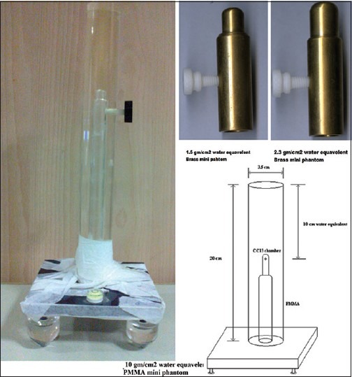
Photograph of PMMA columnar mini phantom and brass build-up cap
Figure 2.
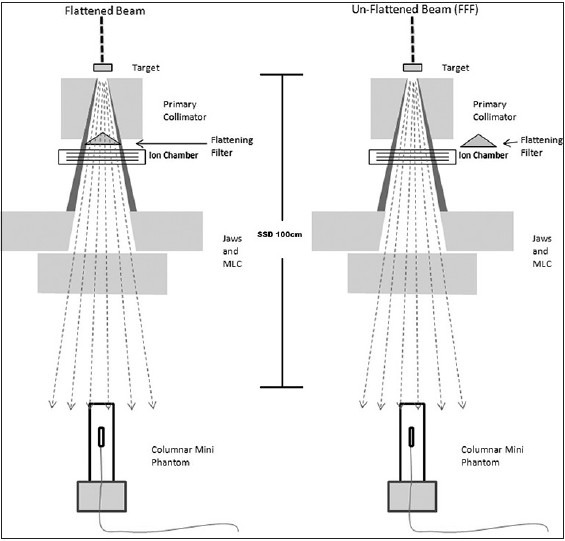
Schematic diagram of columnar mini phantom experimental setup in linear accelerator
Results
Effect of field size on Sc
The total scatter factor (Sc, p) for 6MV-FB, 10MV-FB, 6MV-FFF, and 10MV-FFF photon beams for various field sizes were measured and details are given in Figure 3. The Sc, P values ranged from 0.9283 to 1.1108 for 6MV-FB, 0.9404 to 1.0760 for 6MV-FFF, 0.9335 to 1.0915 for 10MV-FB, and 0.9612 to 1.0440 for 10MV-FFF for field sizes from 5 × 5 cm2 to 40 × 40 cm2 (SSD: 100 cm and SCD: 108.5 cm). Sc, P values of 6MV-FFF and 10MV-FFF were higher than 6MV-FB and 10MV-FB for field sizes up to 10 × 10 cm2. However, as the field size was increased above 10 × 10 cm2, an increase in the values of Sc, P was observed with 6MV-FB and 10MV-FB compared with 6MV-FFF and 10MV-FFF.
Figure 3.
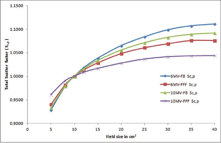
Variation of Sc,p with various field size for 6MV-FB, 6MV-FFF, 10MV-FB, and 10MV-FFF measured in Varian True beam
The head scatter factor for 6MV-FB, 6MV-FFF, 10MV-FB, and 10MV-FFF photon beams for various field sizes were measured with the designed columnar mini phantom in parallel orientation at 10.0 cm equivalent depth and brass build-up cap in perpendicular orientation at 3.42 cm (SSD: 100 cm and SCD: 100.7 cm) and 5.13 cm (SSD: 100 cm and SCD: 100.9 cm) water equivalent depth for Varian Clinac iX and Varian True beam machines. The details are given in Figure 4. A maximum deviation of head scatter values ±0.39%, ±0.08%, ±0.71%, and ±0.28% were observed in various field sizes ranging from 4 × 4 cm2 to 40 × 40 cm2 for Varian True Beam 6MV-FB, 6MV-FFF, 10MV-FB, and 10MV-FFF, respectively, of mini phantom measured values compared to brass build-up cap measured values. The Sc was higher with brass build-up cap measured values than with mini phantom measured values irrespective of the beam energy for larger field size. Sc was higher with mini phantom measured values than with brass build-up cap measured values irrespective of the beam energy for less than 10 × 10 cm2 field size.
Figure 4.
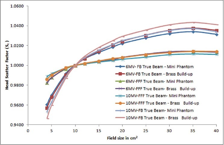
Variation of Sc with field size for with the mini phantom and Brass bulid-up cap at 10.0 cm and approximately the depth of maximum dose water equivalent thickness respectively in Varian True Beam for 6MV-FB, 6MV-FFF, 10MV-FB, and 10MV-FFF beams
The Sc values ranged from 0.9605 to 1.0313 for 6MV-FB, 0.9825 to 1.0133 for 6MV-FFF, 0.9534 to 1.0340 for 10MV-FB, and 0.9887 to 1.0113 for 10MV-FFF beams for field sizes from 4 × 4 cm2 to 40 × 40 cm2. Sc values of 6MV-FFF and 10MV-FFF were higher than 6MV-FB and 10MV-FB up to 10 × 10 cm2 field size. However, as the field size was increased above 10 × 10 cm2, an increased amount of Sc values were observed in 6MV-FB and 10MV-FB than with 6MV-FFF and 10MV-FFF. A significant variation in Sc values was observed in 6MV-FFF and 10MV-FFF compared to 6MV-FB and 10MV-FB and a variation of only 3.1% was observed over the entire range of 5 × 5 cm2 to 40 × 40 cm2 field sizes for 6MV-FFF compared to 7.4% for 6MV-FB and 2.3% and 8.5% for 10MV-FFF and 10MV-FB, respectively.
Effect of SSD on Sc
Figure 5 shows the variation in Sc for different field sizes with different SSDs (80, 100, and 120 cm) for the 6MV-FB, 6MV-FFF, 10MV-FB, and 10MV-FFF photon beams in two different Varian LINACs (Clinac iX and True beam). The Columnar mini phantom of 10-cm water equivalent depth was used for Sc measurements at different SSDs. A significant variation in Sc was noticed for larger field sizes with different SSDs for both the LINACs and for 6MV-FB, 6MV-FFF, 10MV-FB, and 10MV-FFF photon beams.
Figure 5.
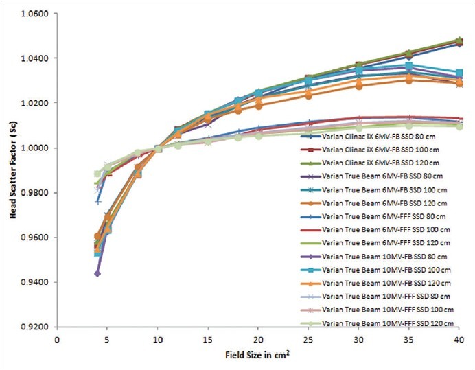
Variation of Sc with field size for different SSD for 6MV-FB, 6MV-FFF, 10MV-FB and 10MV-FFF measured in and Varian linear accelerators (Clinac iX and Truebeam)
Impact of beam shaping devices on Sc
In the clinical work, the beam shaping device (high-Z material) like MLC was used to alter the beam shape as per planning requirements. The mini phantom was used to study the effect of beam shaping devices on Sc. Comparative study was done for fields shaped by only by MLC and fields shaped only by jaws for 6MV-FB, 6MV-FFF, 10MV-FB, and 10MV-FFF in Varian True beam LINAC. The Sc values of ‘Jaw only’ and ‘MLC only’ fields were compared. It was observed that in mini phantom measurement of ‘MLC only’ field, the Sc values increased up to a maximum of 0.7%, 0.5%, 0.6%, and 0.3% for 6MV-FB, 6MV-FFF, 10MV-FB, and 10MV-FFF, respectively, for larger field sizes compared to ‘Jaw only’ field. There was no significant variation of Sc in smaller field sizes irrespective of beam energy [Figure 6].
Figure 6.
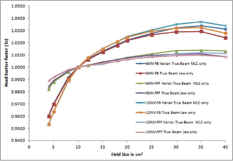
Variation of Sc with field size for field shaped jaw only and jaw and MLC for 6MV-FB, 6MV-FFF, 10MV- FB, and 10MV-FFF measured in Varian Truebeam
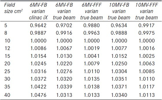
The Sc for the two LINACs (Varian Clinac iX and True beam) was measured for square fields from 4 × 4 cm2 to 40 × 40 cm2 with indigenously designed columnar mini phantom of 10-cm water equivalent depth. The Sc in Clinac iX was higher than the True beam for larger field sizes and lesser in smaller field sizes for 6MV-FB. This could be due to the variation in the design of tertiary collimators (MLC). The maximum deviation of Sc values for 6MV-FB of True beam was 1.1% for larger field sizes with respect to Clinac iX accelerator.
The Sc for 6MV-FB was lesser than the 6MV-FFF in 4 × 4cm2 field sizes, and a maximum deviation of Sc values was 2.3% in True beam LINAC. The Sc for 6MV-FB was higher than the 6MV-FFF in 40 × 40 cm2 field sizes, and a maximum deviation of Sc values was 1.7% in True beam LINAC. The Sc for 10MV-FB was lesser than the 10MV-FFF in 4 × 4cm2 field sizes, and a maximum deviation of Sc values was 3.7% in True beam LINAC. The Sc for 6MV-FB was higher than the 6MV-FFF in 40 × 40cm2 field sizes and a maximum deviation of Sc values was 2.2% in True beam LINAC. The Sc values of both LINACs of 6MV-FB (True beam and Clinac iX) and 6MV-FFF, 10MV-FB, and 10MV-FFF beams of True beam are shown in the Table 1.
Table 1.
The measured Sc values at 10-cm depth for Varian (Clinac iX and Truebeam) linear accelerators at 100 cm SSD
Collimator exchange effect on Sc
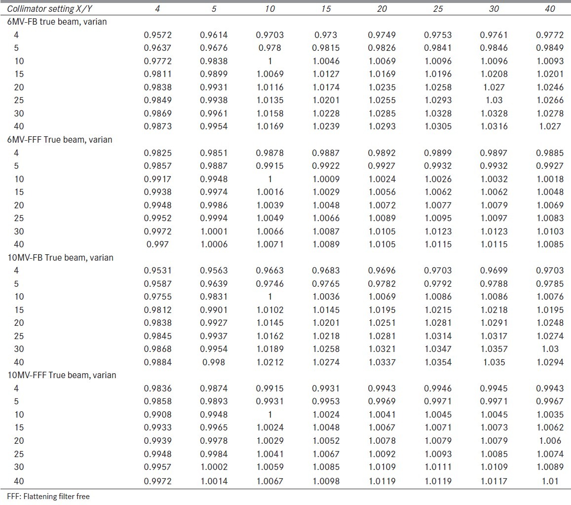
The Sc was measured for the rectangular field to check the collimator exchange effect. The readings for both LINACs are shown in Table 2. In this measurement, Y jaw was always the upper collimator and X was always the lower collimator. Sc value was higher for larger asymmetry fields (40 × 5 cm2) and lesser in smaller asymmetry fields (30 × 40 cm2). With the effect of collimator exchange, Sc values varied from 2.05% to 0.5%(6MV-FB Clinac iX, Varian), 1.03% to 0.37% (6MV-FB), 0.86% to 0.12% (6MV-FFF), 1.99% to 0.48% (10MV-FB), and 0.47% to 0.27% (10MV-FFF) for field sizes from 4 × 40cm2 to 40 × 30cm2 beams produced by True beam LINAC.
Table 2.
Measured Sc values for rectangular collimator settings for open fields of 6MV-FB, 6MV-FFF, 10MV-FB, nd 10MV-FFF of varian true beam linear accelerator
Discussion
The head scatter factor plays a major role in output measurements of mega voltage radiation beams as well as in beam modeling of treatment planning systems used for advanced treatment delivery techniques like IMRT, SRS, SRT, SBRT, etc., with summation of series of MLC shaped fields.[29,38,39,40] There are multiple factors influencing the Sc values, in particular, photons are scattered by structures in the accelerator head (primary collimator, flattening filter, the secondary collimator, tertiary collimators (MLCs), and wedges), photons and electrons backscattered into the monitor chamber, and at very small field sizes a portion of the x-ray source is obscured by the collimators. In recent times, LINAC manufacturers have made provisions to deliver radiation therapy treatments with the flattening filter removed from a traditional medical accelerator. The flattening filter scatters a large number of photons that contribute to the out-of-field dose,[41] and the removal of flattening filter may also reduce the out-of-field dose during IMRT treatment delivery due to reduced head scatter.[42] The type of phantom and depth of measurement of Sc values are topics of interest, as has been reported by several authors.[4,6,14,16,21,26,37] The AAPM therapy physics committee Task Group 74 (TG-74)[25] recommends the build-up caps in cylindrical shapes along with long axis parallel with beam central axis and the ion chamber placed at 10 gm/cm2 water equivalent depth for head scatter factor measurements. The present study reports the design of similar low-Z material mini phantom and its measurements in 6MV-FB, 6MV-FFF, 10MV-FB, and 10MV-FFF photon beams.
Measured Sc, P values of 6MV-FB,6MV-FFF,10MV-FB, and 10MV-FFF plotted against equivalent square in Figure 3 show significant difference between FB and FFF modes and reveal the important contribution of the flattening filter (FF) to the scattered radiation observed in our results. The difference in the two measured curves is due to the reduction of head scatter as the phantom scatter remains essentially the same. Similar results have been shown by Ponisch et al.[43]
Figure 4 shows that Sc is slightly higher (0.7%) with brass build-up cap measured values than with low-Z (PMMA) mini phantom measured values, irrespective of 6MV-FB, 6MV-FFF, 10MV-FB, and 10MV-FFF photon energy beams for larger field sizes. This agrees with the results obtained by Paul A. Jursinic,[21] L. Weber et al.,[44] and Hounsell et al.[29] The result of the present study confirms that build-up cap of high atomic number material causes much greater scatter of electrons[45] and above 10 × 10 cm2 to 40 × 40 cm2 field sizes maximum deviation which was less than 0.5% for 6MV-FB and 6MV-FFF and 0.7% for 10MV-FB and 10MV-FFF photon energies compared to low-Z mini phantoms measurements and reverse for less than 10 × 10 cm2 field size.
The measured Sc values plotted in Figure 4 shows significant differences between 6MV-FB and 6MV-FFF and 10MV-FB and 10MV-FFF modes, and it confirmed the contribution of flattening filter in head scatter radiation. A significant decrease is seen in the range of readings compared to the flattened beam with filter free beam and a variation of Sc values confirmed that only 3.1% (Sc values: 0.9825-1.0133) was observed over the entire range of 4 × 4 cm2 to 40 × 40 cm2 field sizes for 6MV-FFF compared to 7.3% (Sc values: 0.9605-1.0313) for 6MV-FB and corresponds to the findings of Zhu et al. and Jason Cashmore.[46,47] A variation of Sc values confirmed that only 2.2% was observed over the entire range of 4 × 4 cm2 to 40 × 40 cm2 field sizes for 10MV-FFF compared to 8.5% for 10MV-FB. Removal of flattening filter (6MV-FFF and 10MV-FFF) leads to decrease in head scatter and lower whole body dose (reducing the risk of secondary cancers).[48] Reduced head scatter also leads to reduction in penumbra and dose outside of the field edge. The flattening filter-free mode showed smaller field size dependence than did the flattening filter mode.
The role of SSD on the Sc was evaluated by measuring the Sc at different SSD (80, 100, and 120 cm) with low-Z mini phantom at 10-cm water equivalent depth for 6MV-FB, 6MV-FFF, 10MV-FB, and 10MV-FFF photon beams as shown in Figure 6. The results suggest that the SSD had no influence on head scatter for both FB and FFF for smaller fields and significant variation observed in field sizes above 20 × 20cm2. This is in agreement with the results of Rickard et al.[49]
The head scatter factor were measured for MLC only and jaw only shaped fields with and without the flattening filter and for 6MV and 10MV photon beams. Figure 6 shows that, in the flattening filter-free mode in both energy, there is an indication that the head scatter is less for the MLC-shaped fields than for the jaw-shaped fields for field sizes less than 10 × 10 cm2 and higher in field sizes above 10 × 10 cm2. The dependence of the head scatter factor on the field shaped by MLC or Jaw was larger for the 10-MV flattened or unflattened beam than for the 6-MV flattened and unflattened beam. Removing the flattening filter considerably decreased this dependence in higher energy beams compared to lower energy photon beams. These results are similar to those found by Arnfield et al. and Ponisch et al.[43,50]
The present study emphasizes the need for Sc measurements at 10-cm water equivalent depth with mini phantom for 6MV-FB photon beams. This is in agreement with that of Venselaar et al.[25] who recommended Sc measurement at 10-cm water equivalent depth with mini phantom. For flattened beams, square field head scatter factors were compared with that of AAPM, TG-74[25] published data of Varian (Clinac iX (2300CD) accelerator. The present data is in good agreement with published data in TG-74[25] reports.
The measured Sc values of two different LINACs tabulated in [Table. 1] shows significant differences between FF and FFF modes. This reveals the important contribution of the flattening filter to the scattered radiation observed by the detector. Sc values of 6MV-FFF photon beams are lesser than that of the 6MV-FB photons beams (-0.66 - -2.8%, Clinac iX (2300CD; -0.47 - -1.74%, True beam) and a minimum and maximum deviation were observed in 12 × 12 cm2 and 40 × 40 cm2 field sizes, respectively. Sc values of 6MV-FFF photon beams are increased compare to 6MV-FB photons beams (+2.4%, Clinac iX (2300CD; +1.8%, True beam) and maximum deviation was observed in 4 × 4 cm2 field sizes. This is in agreement with the findings of George X. Ding[51] relating to the scattered dose contributions from the flattening filter at the isocenter, which were about 0.9-3% for 6MV-FB photon beams. Sc values of 10MV-FFF photon beams are lesser (-0.61 - -2.19%, True beam) than that of the 10MV-FB photons beams and minimum and maximum deviation were observed in 12 × 12cm2 and 40 × 40cm2 field sizes. Sc values of 10MV-FFF photon beams are increased compare to 10MV-FB photons beams (2.9%, True beam) and maximum deviation were observed in 4 × 4cm2 field sizes.
The collimator exchange effect was studied for 6MV-FB, 6MV-FFF, 10MV-FB, and 10MV-FFF photon beams produced in Clinac iX (2300CD) and True beam LINACs and Sc values are tabulated in Table 2. The collimator was exchanged from 4 × 40 cm2 to 40 × 4 cm2 field sizes. The maximum deviation observed was 1.06% for 6MV-FB, 1.99% for 10MV-FB, 0.85% for 6MV-FFF, and 0.58% for 10MV-FFF in True beam LINAC suggesting that the collimator exchange effect was lower in FFF mode compared to FF mode. The collimator exchange effect might be due to the back scatter from the dose monitor chambers. Thus, the results are consistent with the measured data reported by George X. Ding[51] for both flattened and unflattened photon beams.
Conclusions
A low atomic number columnar mini phantom was designed with PMMA material as per the AAPM therapy physics committee Task Group 74 (TG-74). It was used for measuring the head scatter radiation for 6MV-FB (Clinac iX (2300CD) and True beam), 6MV-FFF, 10MV-FB, and 10MV-FFF photon beams of Varian LINACs, and values were compared with high atomic number brass build-up cap measured values. The measurement of Sc with brass build-up cap was found to be slightly higher than the 10-cm water equivalent depth mini phantom for above 10 × 10cm2 field size and opposite in smaller field size. Sc values of FFF photon beams were lesser than the FF photons beams for field sizes ranging above 10 × 10 cm2 to 40 × 40 cm2. Our results confirm the removal of flattening filter causes a decrease in the head scatter factor. This could reduce the out-of-field dose in advanced treatment delivery techniques. Further, the effect of Sc values with respect to SSD, beam shaping devices (MLC) and collimator exchange effect of both FFF and FF photon beams were studied with indigenously designed mini phantoms and the present work confirms that the results are comparable with previously published data.
Footnotes
Source of Support: Nil
Conflict of Interest: None declared.
References
- 1.Johns HE, Cummingham JR. The Physics of Radiology. 4th ed. Springfield: Charles C. Thomas Publisher; 1983. pp. 336–81. [Google Scholar]
- 2.Khan FM. The Physics of Radiation Therapy. 3rd ed. Philadelphia: Lippincott Williams and Wilkins; 2003. pp. 178–98. [Google Scholar]
- 3.Patterson MS, Shragge PC. Characteristics of an 18 MV photon beam from Therac-20 medical linear accelerator. Med Phys. 1981;8:312–8. doi: 10.1118/1.594833. [DOI] [PubMed] [Google Scholar]
- 4.Spicka J, Herron D, Orton C. Separating output factor in collimator and phantom scatter factor for megavoltage photon calculations. Med Dosim. 1998;13:23–4. doi: 10.1016/s0958-3947(98)90107-8. [DOI] [PubMed] [Google Scholar]
- 5.Luxton G, Astrahan MA. Output factor constituents of a high energy photon beam. Med Phys. 1988;15:88–91. doi: 10.1118/1.596300. [DOI] [PubMed] [Google Scholar]
- 6.Bjärngard BE, Siddon RL. A note on equivalent circles, squares and rectangles. Med Phys. 1982;9:258–60. doi: 10.1118/1.595161. [DOI] [PubMed] [Google Scholar]
- 7.Khan FM, Sewchand W, Lee J, Williamson JF. Revision of tissue-maximum ratio and scatter-maximum ratio concepts for cobalt 60 and high energy x-ray beams. Med Phys. 1980;7:230–7. doi: 10.1118/1.594648. [DOI] [PubMed] [Google Scholar]
- 8.Sharpe MB, Jaffray DA, Battista JJ, Munro P. Extrafocal radiation: A unified approach to the prediction of beam penumbra and output factors for megavoltage x-ray beams. Med Phys. 1995;22:2065–74. doi: 10.1118/1.597648. [DOI] [PubMed] [Google Scholar]
- 9.Jursinic PA. Clinical implementation of a two-component x-ray source model for calculation of head scatter factors. Med Phys. 2001;24:2001–7. doi: 10.1118/1.598113. [DOI] [PubMed] [Google Scholar]
- 10.Shih R, Li XA, Chu JC, Hsu WL. Calculation of head scatter factors at isocenter or at center of field for any arbitrary jaw setting. Med Phys. 1999;26:506–11. doi: 10.1118/1.598549. [DOI] [PubMed] [Google Scholar]
- 11.Palta JR, Yeung DK, Frouhar V. Dosimetric considerations for a multileaf collimator system. Med Phys. 1996;23:1219–24. doi: 10.1118/1.597678. [DOI] [PubMed] [Google Scholar]
- 12.Boyer AL, Ochran TG, Nyerick CE, Waldron TJ, Huntzinger CJ. Clinical dosimetry for implementation of a multileaf collimator. Med Phys. 1992;19:1255–61. doi: 10.1118/1.596757. [DOI] [PubMed] [Google Scholar]
- 13.Zhu TC, Bjärngard BE. The fraction of photons undergoing head scatter in X-ray beams. Phys Med Biol. 1995;40:1127–34. doi: 10.1088/0031-9155/40/6/011. [DOI] [PubMed] [Google Scholar]
- 14.Jursinic PA. Measurement of head scatter factors of linear accelerators with columnar miniphantoms. Med Phys. 2006;33:1720–8. doi: 10.1118/1.2201148. [DOI] [PubMed] [Google Scholar]
- 15.Biggs PJ, Ling CC. Electron as the cause of the observe dmax shift with field size in high energy beams. Med Phys. 1979;6:291–5. doi: 10.1118/1.594580. [DOI] [PubMed] [Google Scholar]
- 16.Biggs PJ, Russell MD. An investigation into the presence of secondary electrons in megavoltage photon beams. Phys Med Biol. 1983;28:1033–43. doi: 10.1088/0031-9155/28/9/003. [DOI] [PubMed] [Google Scholar]
- 17.Luxton G, Astrahan MA. Characteristics of high energy photon beam of a 25 MV accelerator. Med Phys. 1988;15:82–7. doi: 10.1118/1.596163. [DOI] [PubMed] [Google Scholar]
- 18.Mackie TR, Scrimger JW. Contamination of a 15-MV photon beam by electrons and scattered photons. Radiology. 1982;144:403–9. doi: 10.1148/radiology.144.2.6806853. [DOI] [PubMed] [Google Scholar]
- 19.International Commission on Radiation Units and Measurements (ICRU) Report Number 14. 1969 [Google Scholar]
- 20.Attix FH. Introduction to Radiological Physics and Radiation Dosimetry. New York: Wiley; 1986. pp. 231–63. [Google Scholar]
- 21.Jursinic PA, Thomadsen BR. Measurements of head-scatter factors with cylindrical build-up caps and columnar miniphantoms. Med Phys. 1999;26:512–7. doi: 10.1118/1.598550. [DOI] [PubMed] [Google Scholar]
- 22.Padikal TN, Deye JA. Electron contamination of a high-energy X-ray beam. Phys Med Biol. 1978;23:1086–92. doi: 10.1088/0031-9155/23/6/004. [DOI] [PubMed] [Google Scholar]
- 23.Thomadsen BR, Kubsad SS, Paliwal BR, Shahabi S, Mackie TR. On the cause of the variation in tissue-maximum ration values with source-to-detector distance. Med Phys. 1993;20:723–7. doi: 10.1118/1.597022. [DOI] [PubMed] [Google Scholar]
- 24.Marbach JR, Almond PR. Scattered photons as the cause for the observed dmax shift with field size in high energy photon beams. Med Phys. 1977;4:310–4. doi: 10.1118/1.594319. [DOI] [PubMed] [Google Scholar]
- 25.Zhu TC, Ahnesjö A, Lam KL, Li XA, Ma CM, Palta JR, et al. AAPM Therapy Physics Committee Task Group 74. Report of AAPM Therapy Physic Committee task Group 74: In-air output ratio, SC, for megavoltage photon beams. Med Phys. 2009;36:5261–91. doi: 10.1118/1.3227367. [DOI] [PubMed] [Google Scholar]
- 26.van Gasteren JJ1, Heukelom S, van Kleffens HJ, van der Laarse R, Venselaar JL, Westermann CF. The determination of phantom and collimator scatter components of the output of megavoltage photon beams: Measurement of the collimator scatter part with a beam-coaxial narrow cylindrical phantom. Radiother Oncol. 1991;20:250–7. doi: 10.1016/0167-8140(91)90124-y. [DOI] [PubMed] [Google Scholar]
- 27.Olofsson J, Georg D, Karlsson M. A widely tested model for head scatter influence on photon beam output. Radiother Oncol. 2003;67:225–38. doi: 10.1016/s0167-8140(02)00409-7. [DOI] [PubMed] [Google Scholar]
- 28.Ahnesjö A. Analytic modeling of photon scatter from flattening filters in photon therapy beams. Med Phys. 1994;21:1227–35. doi: 10.1118/1.597205. [DOI] [PubMed] [Google Scholar]
- 29.Hounsell AR, Wilkinson JM. Head scatter modeling for irregular field shaping and beam intensity modulation. Phys Med Biol. 1997;42:1737–49. doi: 10.1088/0031-9155/42/9/006. [DOI] [PubMed] [Google Scholar]
- 30.Fu W, Dai J, Hu Y, Han D, Song Y. Delivery time comparison for intensity-modulated radiation therapy with/without flattening filter: A planning study. Phys Med Biol. 2004;49:1535–47. doi: 10.1088/0031-9155/49/8/011. [DOI] [PubMed] [Google Scholar]
- 31.Kragl G, Baier F, Lutz S, Albrich D, Dalaryd M, Kroupa B, et al. Flattening filter free beams in SBRT and IMRT: Dosimetric assessment of peripheral doses. J Med Phys. 2011;21:91–101. doi: 10.1016/j.zemedi.2010.07.003. [DOI] [PubMed] [Google Scholar]
- 32.Kry SF, Titt U, Ponisch F, Vassiliev ON, Salehpour M, Gillin M, et al. Reduced neutron production through use of a flattening-filter-free accelerator. Int J Radiat Oncol Biol Phys. 2009;68:1260–4. doi: 10.1016/j.ijrobp.2007.04.002. [DOI] [PubMed] [Google Scholar]
- 33.Lee PC. Monte Carlo simulations of the differential beam hardening effect of a flattening filter on a therapeutic x-ray beam. Med Phys. 1997;24:1485–9. doi: 10.1118/1.598037. [DOI] [PubMed] [Google Scholar]
- 34.Mesbahi A. Dosimetric characteristics of unflattened 6 MV photon beams of a clinical linear accelerator: A Monte Carlo study. Appl Radiat Oncol. 2007;65:1029–36. doi: 10.1016/j.apradiso.2007.04.023. [DOI] [PubMed] [Google Scholar]
- 35.Titt U, Vassiliev ON, Ponisch F, Kry SF, Mohan R. Monte Carlo study of backscatter in a flattening filter free clinical accelerator. Med Phys. 2006;33:3270–3. doi: 10.1118/1.2229430. [DOI] [PubMed] [Google Scholar]
- 36.Vassiliev ON, Titt U, Kry SF, Mohan R, Gillin MT. Radiation safety survey on a flattening filter-free medical accelerator. Radiat Prot Dosimetry. 2007;124:187–90. doi: 10.1093/rpd/ncm179. [DOI] [PubMed] [Google Scholar]
- 37.Petti PL, Goodman MS, Gabriel TA, Mohan R. Investigation of buildup dose from electron contamination of clinical photon beams. Med Phys. 1983;10:18–24. doi: 10.1118/1.595287. [DOI] [PubMed] [Google Scholar]
- 38.Fippel M, Haryanto F, Dohm O, Nüsslin F, Kriesen S. A virtual photon energy fluence model for Monte Carlo dose calculation. Med Phys. 2003;30:301–11. doi: 10.1118/1.1543152. [DOI] [PubMed] [Google Scholar]
- 39.Sharpe MB, Miller BM, Yan D, Wong JW. Monitor unit settings for intensity modulated beams delivered using a step-and-shoot approach. Med Phys. 2000;27:2719–25. doi: 10.1118/1.1328383. [DOI] [PubMed] [Google Scholar]
- 40.Yang Y, Xing L, Li JG, Palta J, Chen Y, Luxton G, et al. Independent dosimetric calculation with inclusion of head scatter and MLC transmission for IMRT. Med Phys. 2003;30:2937–47. doi: 10.1118/1.1617391. [DOI] [PubMed] [Google Scholar]
- 41.Naqvi SA, Sarfaraz M, Holmes T, Yu CX, Li XA. Analysing collimator structure effects in head-scatter calculations for IMRT classfields using scatter raytracing. Phys Med Biol. 2001;46:2009–28. doi: 10.1088/0031-9155/46/7/320. [DOI] [PubMed] [Google Scholar]
- 42.Cozzi L, Buffa FM, Fogliata A. Dosimetric features of linac head and phantom scattered radiation outside the clinical photon beam: Experimental measurements and comparison with treatment planning system calculations. Radiother Oncol. 2001;58:193–200. doi: 10.1016/s0167-8140(00)00317-0. [DOI] [PubMed] [Google Scholar]
- 43.Ponisch F, Titt U, Vassiliev ON, Kry SF, Mohan R. Properties of unflattened photon beams shaped by a multileaf collimator. Med Phys. 2006;33:1738–46. doi: 10.1118/1.2201149. [DOI] [PubMed] [Google Scholar]
- 44.Weber L, Nilsson P, Ahnesjö A. Build-up cap materials for measurement of photon head-scatter factors. Phys Med Biol. 1997;42:1875–86. doi: 10.1088/0031-9155/42/10/002. [DOI] [PubMed] [Google Scholar]
- 45.Evans RD. The Atomic Nucleus. Malabar: Kriegler Publishing; 1985. Elastic scattering of electrons and positrons; pp. 592–9. [Google Scholar]
- 46.Zhu XR, Kang Y, Gillin MT. Measurement of in-air output ratios for a linear accelerator with and without the filleting filter. Med Phys. 2006;33:3723–33. doi: 10.1118/1.2349695. [DOI] [PubMed] [Google Scholar]
- 47.Cashmore J. The characterization of unflattened photon beams from a 6MV linear accelerator. Phys Med Biol. 2008;53:1933–46. doi: 10.1088/0031-9155/53/7/009. [DOI] [PubMed] [Google Scholar]
- 48.Hall EJ, Wuu CS. Radiation-induced second cancers: The impact of 3D-CRT and IMRT. Int J Radiat Oncol Biol Phys. 2003;56:83–8. doi: 10.1016/s0360-3016(03)00073-7. [DOI] [PubMed] [Google Scholar]
- 49.Sjögren R, Karlsson M. Electron contamination in clinical high energy photon beams. Med Phys. 1996;23:1873–81. doi: 10.1118/1.597750. [DOI] [PubMed] [Google Scholar]
- 50.Arnfield MR, Siebers JV, Kim JO, Wu Q, Keall PJ, Mohan R. A method for determining multileaf collimator transmission and scatter for dynamic intensity modulated radiotherapy. Med Phys. 2000;27:2231–41. doi: 10.1118/1.1312190. [DOI] [PubMed] [Google Scholar]
- 51.Ding GX. An investigation of accelerator head scatter and output factor in air. Med Phys. 2004;31:2527–33. doi: 10.1118/1.1784131. [DOI] [PubMed] [Google Scholar]


