Abstract
The edge chipping resistances of six CAD/CAM dental restoration materials are analyzed and correlated to other mechanical properties. A new quadratic relationship that is based on a phenomenological model is presented.
Objective
The purpose of this study was to further analyze the edge chipping resistance of the brittle materials evaluated in Part 1. One objective was to determine why some force-distance trends were linear and others were nonlinear. A second objective was to account for differences in chipping resistance with indenter type.
Methods
Edge chipping experiments were conducted with different indenters, including some custom-made sharp conical indenters. A new force – distance quadratic expression was correlated to the data and compared to the linear and power law trends.
Results
The new quadratic function was an excellent fit in every instance. It can account for why some materials can be fit by a linear trend, while others can be fit by the power law trend. The effects of indenter type are accounted for variations in crack initiation and by the wedging stresses once an indentation hole is created.
Significance
The new quadratic force – edge distance function can be used with edge chipping data for all brittle materials, not just those evaluated in this study. The data trends vary from linear to nonlinear depending upon the material’s hardness, fracture toughness, and elastic modulus.
Keywords: Edge chipping, Edge toughness, Dental restorative materials, 3Y-TZP zirconia, Alumina, Filled-resin composite, Glass ceramic, Porcelain, Hardness, Fracture toughness, CAD/CAM
1. Introduction
Part 1 showed how the edge chipping test may be used to evaluate CAD/CAM dental restoration materials [1]. The traditional linear analysis [1–11] that relates the force to create a chip (F) to the distance from the edge (d) is:
| (1) |
The constant Te is the “edge toughness” which is the slope of a line on a force versus distance plot. Edge toughness varies with indenter type and quantitative values could vary by as little as 10% or as much as a factor of two with indenter for a given material [11]. The edge chipping methodology and Eq. (1) were recently applied to brittle denture tooth materials [12]. Fig. 1 shows contrasts in the chips and indentations in a hard dental ceramic and a soft denture tooth material.
Fig. 1.
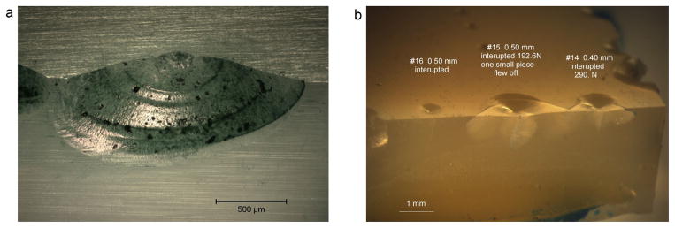
Edge chips in two materials showing contrasts in the indentation size relative to the chip size. (a) shows a chip with a small indentation in the 3Y-TZP. (b) shows chips with large indentations in a brittle denture tooth material. The tests were interrupted prior to the chip popping off.
Part 1 showed that a power law relationship often was a better fit to the data:
| (2) |
where A and n are constants. Thouless et al. [13] derived a model based on buckling of an edge flake that predicted n = 3, but their loading geometry was somewhat different than the usual edge chipping procedures with pointed indenters. (The forces in their model and experiments were applied in a distributed fashion parallel to the edge and at a location between the crack and the side surface.) They obtained:
| (3) |
where λ is a constant, E is the elastic modulus, cf is the critical crack length at instability. An indentation fracture mechanics model for edge chipping by Chai and Lawn [14] for edge chip resistance supports the power law Eq. (2), but only for the case of n = 1.5. Although some of our data in Part 1 [1] and earlier work [11] matched the power law with n = 1.5, much of the data did not. Our exponents ranged from as small as 1 to as large as 2.
As discussed in Part 1, the nonlinearity and the dependence of results on indenter type stem from the multistep chipping process: (a) formation of a small indentation; (b), formation of short stable radial cracks; (c), propagation of some of the radial cracks downward and parallel to the side surface; and (d), unstable crack propagation toward the side surface of one or a pair of cracks causing the chip to pop off. In some of the experiments described in Part 1 [1], the experiments were interrupted and the specimens examined prior to chip pop-off. There were significant differences in steps (a) and (b) depending upon indenter type. At small forces the relatively blunt Rockwell C indenter created shallow depressions with no cracking. Radial or cone cracks initiated only at larger forces. Vickers or 120° sharp conical indenters initiated cracks at small forces. Thus it is not surprising that the force-distance trends are different and that much greater force was needed to form chips with the Rockwell C indenter. Different amounts of deformation and fracture occur during a test sequence and nonlinear effects should be expected.
Although Part 1 showed that much of the data could be matched by the power law Eq. (2), problems remained with the interpretation of the exponent n and the constant A. Is n a fundamental material parameter indicative of a material’s chipping behavior? Can it be related to other material properties such as fracture toughness?
Similar questions have arisen in the past about interpretations of power law fits of hardness data for brittle materials. As will be shown below, a simple relationship that has found widespread utility for interpreting hardness data may have an analog for edge chipping. There are some parallels in hardness and edge chip testing. Both involve deformation and fracture. Fracture around an indentation can alter the hardness response of brittle materials and can dramatically change the “indentation size effect (ISE)” [15–26] whereby hardness varies with force or indentation size.
The hardness, H, of a material is determined by the ratio of an applied load to the contact (or projected) area of an indentation:
| (4) |
where F is the applied load, l is a measure of the indentation size (typically, the diagonal size) and the constant depends on indenter geometry. Hardness usually varies with indentation force. The hardness of ceramics is very high at small indentation forces. Hardness decreases with increasing force and gradually approaches a constant value at large force. Data are sometimes fitted to the Meyer law: [16,27–29]
| (5) |
where C is a constant and n is the Meyer or logarithmic index denoting the degree of curvature for the hardness-load relationship. (This n is not the same as the one in Eq. (1).) If n = 2, hardness is constant and independent of the force. For most ceramics, n < 2, and hardness decreases with increasing force. There is no theoretical basis for applying the Meyer law to brittle materials. Although some (e.g., Sargent and Page [30,31]) have designated group of ceramics with comparable values, the exponents ultimately did not provide much insight as to material behavior.
The inadequacy of the Meyer analysis for brittle materials and metals alike led to alternative curve fits to hardness-force or hardness-indentation size data. Bernhardt [32] proposed a function in 1941:
| (6) |
where F is the load, l is the indentation diagonal size, and a1 and a2 are constants. Mitsche [33] in 1948 and Bückle [34] in 1954 discussed a similar power series expansion:
| (7) |
The constant a0 may correspond to an elastic deformation or residual stresses from specimen preparation [23,35], but it is often set to zero. The simple quadratic function Eq. (6) may be modified by multiplying both sides by l:
| (8) |
There is a physical foundation for the polynomial fits, Eqs. (6) and (8). The term Fl is proportional to the external work done by the indenter which is a function of F and h, the indenter penetration depth. h is proportional to l for self-similar indentations.
Bernhardt [32] related the a1l term in Eq. (6) to “the surface created by the indentation” which includes not only the area of the indentation faces, but also surfaces of internal structural defects. A number of investigators have attempted to correlate surface energy or fracture processes to the a1 term [26,33–41]. The fracture could either be formation of large cracks emanating from Vickers or Knoop indentation corners, or dense microfracture damage zones in and around the indentation. Li et al. [38,39] related this term to frictional and elastic contributions in their “proportional specimen resistance” model.
Bernhardt [32] related the a2l2 term to plastic deformation. Others have described it as the “work of permanent deformation” [37] or the “volume energy of deformation,” [38,39] or the a2 term as the “true hardness,” [36] in the absence of fracture or other surface effects.
So the quadratic polynomial expression has found widespread acceptance for hardness data interpretation. The inclusion of separate terms for fracture and deformation processes seems to be very appropriate for brittle materials. It should be borne in mind that there may be interactions between the fracture and deformation terms. A strict apportionment of energy contributions may be a simplification. For example, Yoo et al. [42] showed that fracture around an indentation enhanced the plasticity of MgO.
Quinn and Quinn [40,41] analyzed the overlapping contributions of cracking and deformation to the ISE trends. They showed a dramatic change in the ISE trend occurred at a critical force or indentation size. The transition correlated with the material’s brittleness, B, a new index of the brittleness:
| (9) |
B is a ratio of the energy of deformation (e.g., H, hardness) to the energy of fracture, (e.g., fracture surface energy or GIc, the critical strain energy release rate) for a material.
The widespread and successful application of Eqs. (6) and (8) to hardness data for brittle materials, and the physical significance of the a1 and a2 terms, suggests that a similar quadratic relationship may be applicable to edge chipping:
| (10) |
where here F is the force on the indenter at the instant a chip pops off, d is the distance away from the edge, and a1 and a2 are constants, different from those in Eqs. (6)–(8). Multiplying each side by d, gives:
| (11) |
Although this equation has units of energy, and surface and volume components, one must be careful since the edge distance is perpendicular to the axis of force application. In this paper, this equation is applied to the data of Part 1 [1]. At the present, this model of edge chipping resistance is phenomenological in nature. Further analysis is deferred to the Discussion section where it is shown that the terms may have fundamental significance.
Three topics are explored in this paper. First, experiments that clarify the role of indenter type on chipping resistance are reported. Second, the new force – distance trend is applied to the data. Third, the edge chip resistance parameters are correlated to properties such as fracture toughness and hardness.
2. Materials and methods
The properties the six commercial CAD/CAM materials that were evaluated in Part I1 are shown in Table 1 of Part 1. Properties include: H, hardness; E, elastic modulus; KIc, fracture toughness; GIc, critical strain energy release rate; and B, brittleness. Data for a fully dense polycrystalline alumina from a different study is added here for comparison [43,44]. The alumina was fully dense, and had an average grain size of 3 μm, a HV(9.8 N) of 16.6 GPa (0.5),2 an elastic modulus of 400 GPa, a KIc as measured by chevron notched beam of 3.61 (0.13) MPa√m, a GIc of 32.6 J/m2, and a brittleness, B, of 510 × 10−6 m.
Table 1.
Edge chip results for the feldspathic porcelain.a
| Material | Indenterb | Distance range (mm) | N | Edge toughness Te, slope of linear Eq. (1) (N/mm) | Power law Eq. (2) |
|---|---|---|---|---|---|
| Feldspathic porcelain small bend bars | 90° SC | 0–0.50 | 25 | 89 (6) | F = 114 d1.25 |
| 100° SC | 0–0.50 | 25 | 116 (8) | F = 214 d1.67 | |
| 120° SC | 0–0.50 | 26 | 138 (5) | F = 168 d1.20 | |
| 140° SC | 0–0.50 | 25 | 223 (14) | F = 279 d1.23 | |
| Feldspathic porcelain Large blocks | 120° SC | 0–0.60 | 35 | 164 (10) | F = 238 d1.46 |
| Rockwell C | 0–0.60 | 27 | 327 (25) | F = 284 d0.80 | |
| Vickers | 0–0.60 | 31 | 224 (12) | F = 370 d1.55 |
Uncertainties are ± one standard deviation.
SC denotes sharp conical.
New experiments on the effect of indenter type were performed on the feldspathic porcelain (Mark II®, Vita Zahnfabrik, Bad Sackingen, Germany) using specimens ground and polished from small 3 mm × 4 mm cross section flexural strength bars. Sharp conical scribe indenters with angles of 90°, 100°, and 140° were used in addition to our customary 120° indenter. The same commercial edge chipping machine described in Part I was used to make the new chips. Force was gradually applied in displacement control at 1 mm/min until the chip abruptly fractured off the specimen.
3. Results
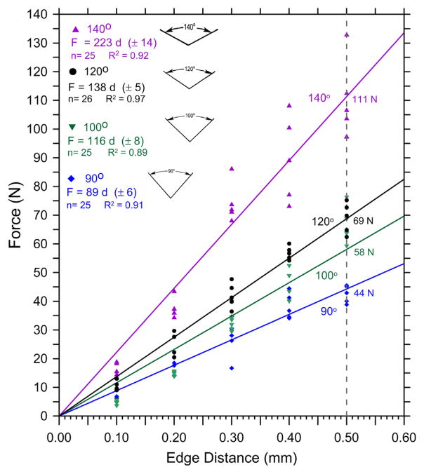
Fig. 2 and the first four entries in Table 1 show the results for different sharp conical indenters on the feldspathic porcelain. All data in Fig. 2 and the first four rows of Table 1 are for data collected on the small bar specimens. For these small test pieces the data were collected only over a range of 0–0.50 mm. A linear curve fit was adequate for the purposes of comparison for the data collected over this narrow range. (Part 1 showed that the data for this material over the greater range 0–0.60 mm was better fit by the power law function, with exponents from 1.2 to 1.5). The slopes of the lines in Fig. 2, the edge toughness, Te, varied with indenter shape. Blunt indenters required more force to cause fracture.
Fig. 2.
Results on one batch of feldspathic porcelain material, but with different sharp conical indenters. The dashed vertical line at d = 0.5 mm and the intercepts with the trend lines correspond to the “edge strengths” as discussed in Part 1.
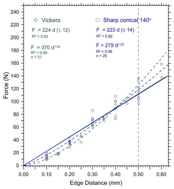
The second set of three rows in Table 1 list data reported in Part 1 (see Fig. 7 of Part 1) on larger blocks from a different batch of the feldspathic porcelain over a larger 0–0.60 mm range, whereby the nonlinearity became more apparent. Nevertheless, Fig. 3 shows that the new 140° sharp conical data matched the Vickers data from Part 1 very well: the linear fits overlapped and the edge toughness values, Te, were indistinguishable.
Fig. 7.
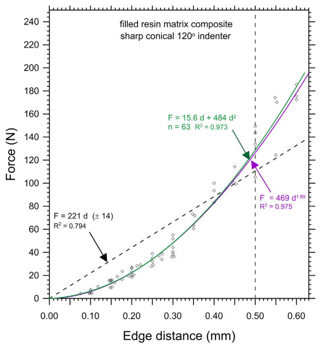
Edge chip results for the filled resin composite.
Fig. 3.
Comparison of results for the Vickers and sharp conical 140° indenters for the feldspathic porcelain.
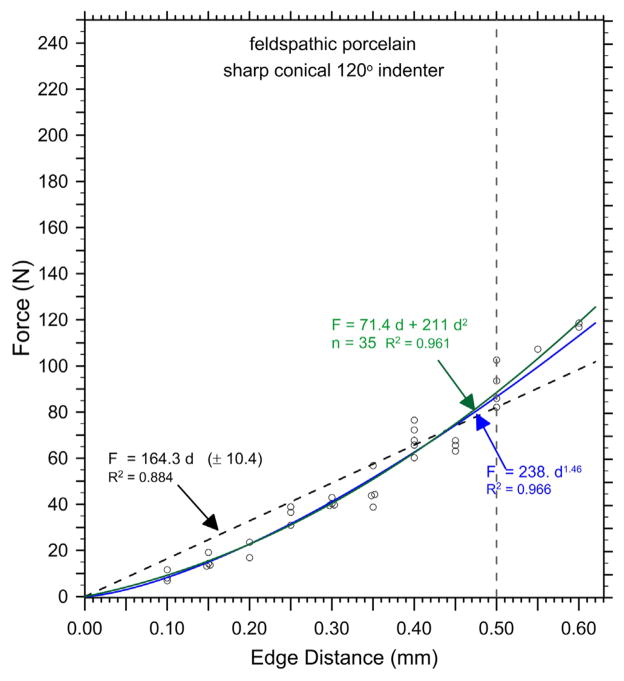
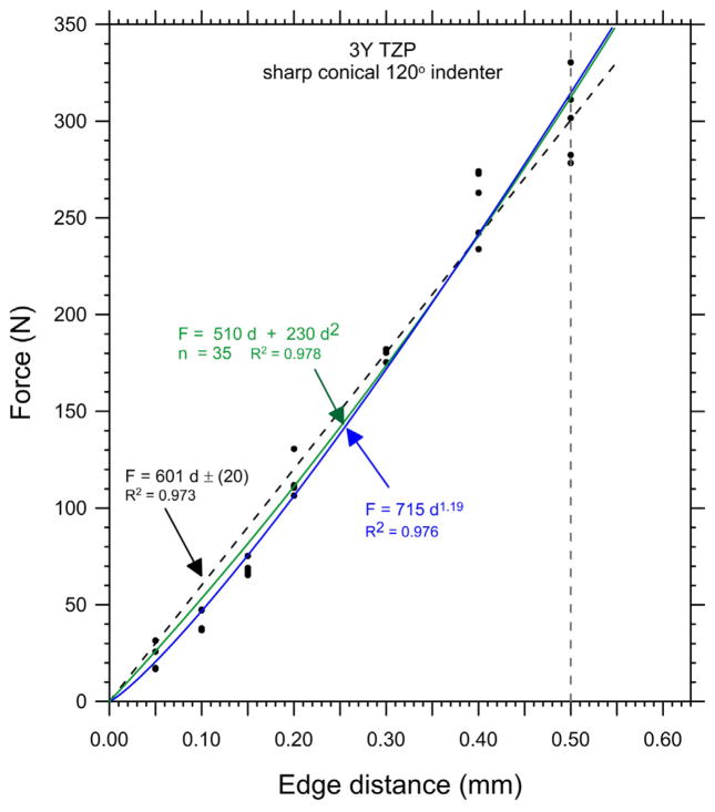
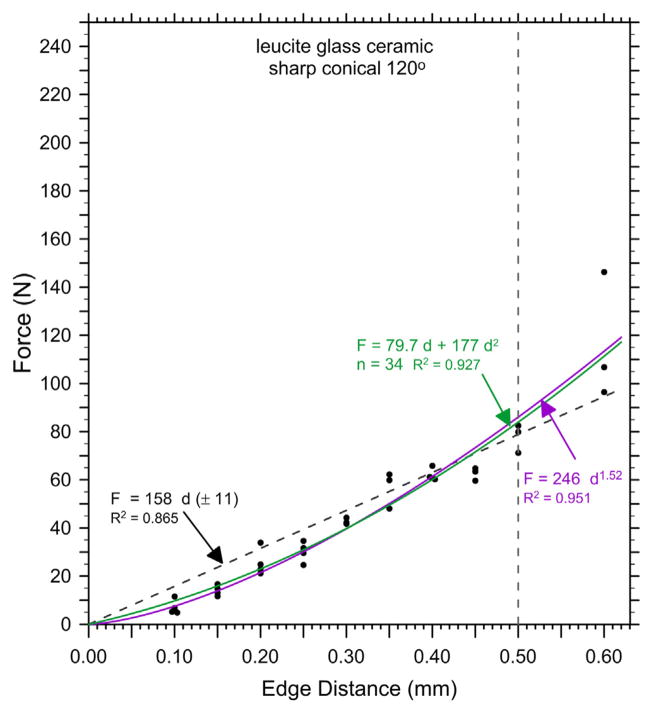
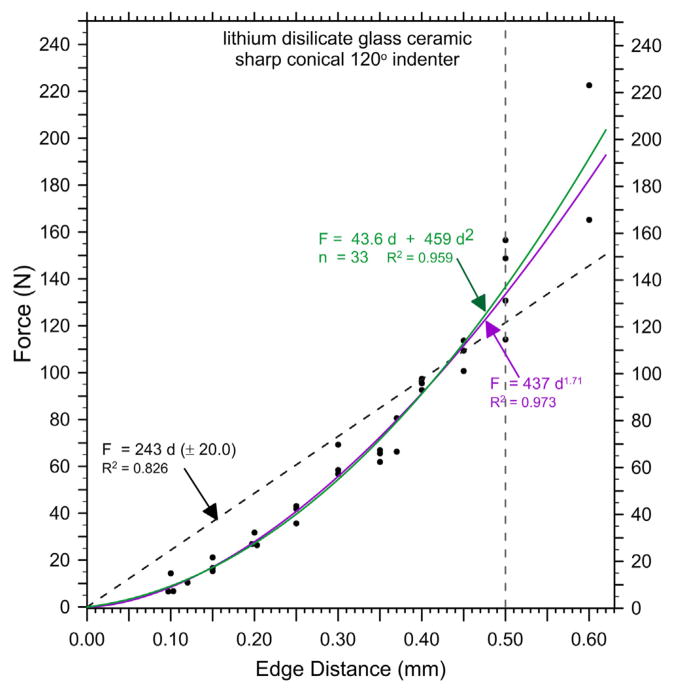
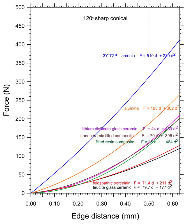
Figs. 4–8 and Table 2 show the edge chip data of Part 1 is fitted very well with the new quadratic relationship, Eq. (10). Two of the quadratic curves (Figs. 4 and 5 for the feldspathic porcelain and the leucite glass ceramic) overlapped the power law function with n ≈ 1.5, in accordance with the model of Chai and Lawn [14]. Figs. 6 and 7 (for the lithium disilicate glass ceramic and the filled resin matrix composite) show how the quadratic fit overlapped the power law fit with n greater than 1.5. Results for the nanoceramic filled composite are not shown but are similar to the lithium disilicate glass ceramic and filled resin composites. Fig. 8 shows how the linear, power, and quadratic fits were very similar for the 3Y-TZP. Fig. 9 combines all the results including those for the alumina and shows that the edge chip results for the dental materials form three groupings.
Fig. 4.
Edge chip results for the feldspathic porcelain with the 120° sharp conical indenter.
Fig. 8.
Edge chip results for the 3Y-TZP zirconia.
Table 2.
Edge chip parameters.
| Material | A (N/mn) constant power law Eq. (2) | n Exponent power law Eq. (2) | a1 (N/m) term a1d quadratic Eq. (9) | a2 (N/m2) term a2d2 quadratic Eq. (9) |
|---|---|---|---|---|
| Zirconia, 3Y-TZP | 715 | 1.18 (0.03) | 510 | 230 |
| Alumina | 522 | 1.47 (0.05) | 193 | 362 |
| Lithium disilicate glass ceramic | 437 | 1.71 (0.05) | 44 | 459 |
| Nanoceramic filled composite | 403 | 1.61 (0.04) | 70 | 396 |
| Filled resin composite | 419 | 1.83 (0.03) | 16 | 484 |
| Feldspathic porcelain | 238 | 1.46 (0.05) | 71 | 211 |
| Leucite glass ceramic | 246 | 1.52 (0.06) | 80 | 177 |
Fig. 5.
Edge chip results for the leucite glass ceramic.
Fig. 6.
Edge chip results for the lithium disilicate glass ceramic.
Fig. 9.
Comparative trends for six dental restoration materials and the alumina.
4. Discussion
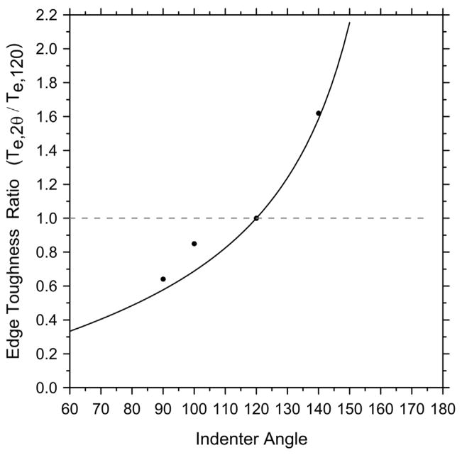
The role of indenter type may be accounted for by a simple model based on the wedging forces that act to open a crack. Appendix A has a simple model that relates the chipping force for a sharp indenter of included angle 2θ to that of a sharp conical 120° indenter:
| (12) |
The edge toughness Te values from a linear regression of F–d curves should also have the same ratio and the results are illustrated in Fig. 10 for the feldspathic porcelain. The correlation is outstanding, notwithstanding the assumptions and simplifications of the analysis. The sharper the indenter, the less the force necessary to make a chip. A Vickers indenter has face-to-face angles of 136° 30° and edge-to-edge angles of 148°. The weighted average of these angles is of the order of 140° and, as Fig. 3 shows, the linear edge chip resistances measured by the 140° sharp conical and the Vickers indenters are indistinguishable.
Fig. 10.
Normalized edge toughness as a function of included indenter angle, 2θ. The line is the predicted tend from Eq. (12) based on wedging forces.
Additional factors such as the nucleation and initial direction of the cracks also cause the edge chip resistances to vary between indenter type. A sharp conical indenter creates a random starburst array of small cracks around the indentation periphery. The ones that are parallel or slightly aimed toward the edge are likely to become dominant, but we have observed instances where initial cracks that aimed into the bulk became dominant. The usual convention with Vickers indenters is to align one of the axes parallel to the specimen side so that the starter cracks are parallel to the specimen edge. One might think that this consistency of the starter crack orientation would lead to less scatter in the Vickers edge chip data, but a review of the data in Part I showed that such is not necessarily the case. The Rockwell C indenter is more problematic since it has a blunt tip. At short distances and small forces, it does not nucleate any cracks. When cracks eventually do nucleate at greater forces, they are more apt to be cone cracks that then have to curve downwards and evolve to form larger cracks parallel to the side surface during the chipping process. It is therefore not surprising that the Rockwell C indenter needs greater force to make chips.
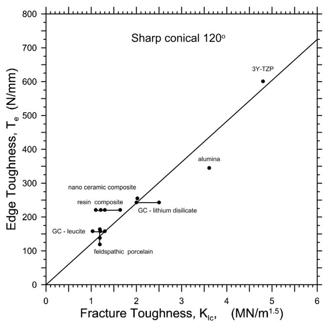
Fig. 11 shows edge toughness, Te, versus fracture toughness, KIc. Despite the fact the Te estimate is based on a simple linear regression of the F–d data, the correlation is satisfactory with a correlation coefficient, R2, of 0.97. The four data points connected by a vertical bar for the feldspathic porcelain, correspond to several estimates of Te that were obtained from different sample sets as reported in Part 1. Multiple points connected by horizontal lines for other materials correspond to different values of KIc in Table 1 of Part 1. For example, the filled resin composite had one KIc estimate of 1.1 MN/m1.5 from fractographic analysis of 50–100 μm critical flaws in strength test specimens [45]. An alternative value of 1.3 MN/m1.5 was from short-bar chevron-notch testing [46] and closely matches a compact tension plateau fracture toughness of 1.2 MN/m1.5 (on a rising R-curve) obtained for a very similar variant of this material in a study by Shah et al. [47]. The latter two KIc values are for cracks that grew a half millimeter or more, not unlike the size of the edge chips in this study. The single edge V-notched beam (SEVNB) estimate of 1.64 MN/m1.5 may be too high, due to notch root issues. A similar, but not quite as good, correlation of edge toughness, Te, to fracture toughness, KIc, was found with the Te data in Part 1 from Vickers edge chip testing. Poor correlations were obtained between Te (by either sharp conical 120° or Vickers indentation) and the critical strain energy release rate, GIc, and with brittleness, B.
Fig. 11.
Edge toughness versus fracture toughness. The bars connect multiple entries for a particular material based on multiple fracture toughness or edge toughness entries.
The quadratic Eq. (10) and power law Eq. (2) functions were usually better fits to the data than the simple linear relationship, Eq. (1). While it might be argued that with enough terms and fitting parameters, any function can match a data set, both Eqs. (10) and (2) have only two parameters. A review of the data in Tables 1 and 2 shows that for the materials that had a strong power law exponent, n > 1.6, the quadratic a2 term was large and the a1 term was small. On the other hand, for the 3Y-TZP where the force-distance data was nearly linear (n = 1.2), the quadratic a1 term dominated. In the intermediate cases with n ≈ 1.5, the a1 and a2 terms were comparable. A review of nearly all of the edge chipping data collected over more than a decade for nearly forty ceramic, composite, and resin materials shows that all of the data can be fit by force –distance trends that range from linear (n = 1) to the power law with a maximum n of 2.0 [11]. Hence, the quadratic function can cover a range of edge chipping behavior for almost all brittle materials. It is very interesting that the two oldest materials with the weakest edge chip resistances, the feldspathic porcelain and the early generation leucite glass ceramic, have low a2/a1 ratios and the power law exponents n ≈ 1.5. They are brittle and “chippy.”
So what do the a1 and a2 terms in the quadratic phenomenological model mean? A simple adaptation of the quadratic Eq. (10) converts it into a form (Eq. (11)) that has units of energy, but as noted in the Introduction, some caution must be exercised. The F and d (force and dimension) vectors are not parallel. Work is the force times the distance traveled in the same direction. Nevertheless, the analysis in the appendix shows that the vertically applied force can be transformed into a lateral wedging force that acts in the same direction as d.
Some concepts from instrumented indentation analysis may be applied to the edge chip process. The indenter applies energy to the system which is converted into elastic and plastic deformations associated with the formation of an indentation, and also the formation and propagation of cracks. The indenter force, F, is a function of the depth of penetration, h: [48]
| (13) |
where the exponent m = 2 for a sharp conical indenter. Ap is a constant appropriate for elastic–plastic contact and has units of N/m2:
| (14) |
where α is the half included indenter angle and is 60° for a 120° indenter. H is the hardness at large enough forces such that it is constant, and E* is the combined modulus incorporating the indenter and test material elastic moduli [48]. So Eq. (13) shows that force depends upon the square of the depth.
Indenter work is the integral of the area under the force–displacement curve
| (15) |
This expression shows that the indenter energy depends upon the cube of the depth of indenter penetration. Utot includes both the elastic and plastic contributions to deformation. Using H = F/πa2, where a is the indentation radius, and combining Eqs. (13)–(15), the total indenter work may be expressed several ways:
| (16) |
The right hand side shows that the indenter work can be expressed in terms of the indention radius a, a dimension in the same direction as the edge distance d. The first term on the right inside the brackets reflects the plastic component of the indentation, whereas the second term adds the elastic component whose significance depends upon the ratio of H to E. For a rigid system with high E, the second term is negligible and all the work is expended in plastic deformation. While it might seem surprising to see indention work expression expressed in terms of the indentation diagonal size, it should be remembered that the diagonal size is simply related to the indentation depth for a sharp conical indenter.
Some of the externally applied energy may be expended in crack formation and propagation. Prior to attempting to correlate the a1 term to fracture energies, the complexities in the state of stresses and strains near an edge are considered. In the edge chipping process, force is applied at either a constant displacement or constant loading rate to the point of fracture. Loading “hiccups” may occur with stable crack extension and change of compliance of the edge if a chip partially detaches prior to pop off. Chipping experiments are usually done without careful recording of force-displacement data and only the peak force at fracture is measured. We have recently started to monitor loading curves. The limited data collected to date are linear to fracture with no “hiccups” or pronounced unloadings. Some evidence (from post-mortem measurement of indentation shapes) suggests that as a chip begins to detach from a test piece, the indenter may rest more on the intact side. Changes of compliance and shifting of the force distribution around an indentation are difficult to model. Cotterell and Kaminga [49,50] show that compliance changes and bending of a partially detached flake are important factors in the formation of long slender flakes. A model of indentation contract stresses in the vicinity of an edge without crack formation by Schwarzer et al. [51] showed dramatic changes in the stress and strain fields near edges once the contact indentation periphery reached approached the edge. Indentation shapes could be distorted and the side wall pushed outwards. Metallographic techniques were used in an early study by Samuels and Mulhearn [52] to show distortions in the elastic–plastic boundary in indentations placed near edges. In some cases the boundary extended to the side surface. Their work led to recommendations for a minimum distance of an indentation away from a test piece edge for hardness testing. Obviously, such guidelines are not applicable to edge chipping experiments. Fig. 1 and other images in [12] show indentation distortions for brittle denture tooth materials with low hardness and elastic modulus. Our point here is that dramatic changes in the stress and strain fields can occur around an indention site and a crack during the edge chipping test sequence. A detailed mechanistic model may be problematic, and a global energy balance approach may be more fruitful.
By analogy with the hardness Eqs. (6) and (7), the a1 term in quadratic Eq. (11) for edge chipping may be associated with surface phenomena and fracture energies. The cracks sizes and the forces in the chipping problem are much larger than those in the hardness problem, however. Prior work on edge chipping indicates that chip shapes are remarkably consistent, irrespective of material type [2,3,14,53] for a particular edge shape and indenter approach angle. (Most of the experiments have used 90° edges with vertically applied forces. If the shape of the edge or the indentation angle are changed, the chip geometries are altered [6,54]. McCormick and Almond [3] stated: “In general, there exists linear relationships between the maximum width, depth and thickness (distance from edge) of flakes.” So although the chips form curved fracture surfaces, the dimensions, the shape, and hence the area, are linearly dependent upon the edge distance d. For the Rockwell C indenter that they used, the final chip height, C, to edge distance, d, ratio was 4.0. Analysis and experimental observations on transparent materials [13,14] show that once a crack initiates at the contact site, it grows downward into the bulk. It remains parallel to the side surface for a considerable distance. Eventually it becomes unstable and suddenly curves toward the side and pops off. Thouless et al. [13] measured the chip height C to be about six times the chip depth, d. (Their loading system was a little different than what is usually used for edge chipping experiments, however. They distributed a force over a short length parallel to the edge, at a location not quite directly over the stably running crack.) Chai and Lawn [14] with Vickers indentation loading found that the critical crack length, c, of stable extension was twice the edge distance, d. The final height of the popped-off chip was typically C = 5.1d and the width was D = 8.0 d. McCormick and Almond found that C/d = 3.8 with Rockwell indenters [2,3]. The area of the approximately semicircular chip at the instability point is proportional to c2. For a given geometry, the total area of the popped-off chip is proportional to C·D. The fracture surface energy, Ufract, expended in forming the edge flake areas, Afract is:
| (17) |
where γf is the fracture surface energy. The actual total fracture energy should also include the additional fracture energy associated with the array of short starburst cracks emanating from the initial indentation and the microfracturing immediately underneath the indentation, but these contributions may scale with the indentation and chip size. So since c, C, and D are proportional to the edge distance, d, the energy of fracture in the formation of chip is proportional to d2, which matches the a1 first term on the right of Eq. (11).
| (18) |
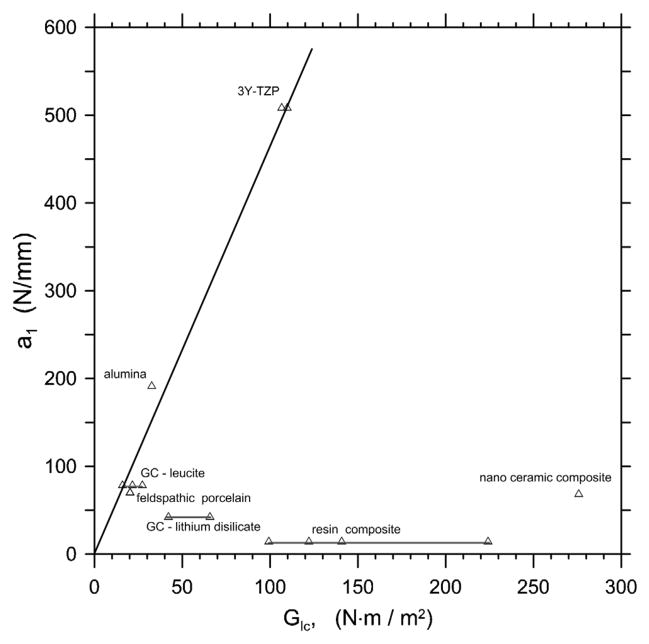
Fig. 12 shows a1 versus GIc. Note both parameters have comparable units: force/length or work/area. The ceramics seem to fit a trend marked by the line in the figure, but the two resin matrix composites are well off the trend. The latter had significant plastic deformation around the indentation sites and the a2 term dominated the best quadratic fit. The lithium disilicate glass ceramic also falls off the trend line, and suggests that the microstructure promoted microfracturing and localized deformation that contributed to its large value of a2 and small value of a1.
Fig. 12.
Quadratic term a1 versus the critical strain energy release rate, GIc. The bars connecting data points correspond to different estimates of GIc from the different KIc outcomes in Table 1.
By analogy with the hardness Eqs. (6) and (7), the a2 term in the edge chipping quadratic Eqs. (10) and (11) may be associated with deformation processes and not fracture. Hardness, which is force per unit projected area of an indentation, is equivalent to the work required to produce a unit volume of plastic deformation [48]. Thus, the plastic energy Up associated with making a conical indentation of radius a and depth, ht can be expressed:
| (19) |
where θ again is the half included angle of the sharp conical indenter. An initial inspection of Eq. (19) suggests that the harder the material, the more the energy expended in deformation. H and a are related, however. The greater the hardness, the smaller is the indentation size and volume. Fischer-Cripps [48] showed that:
| (20) |
Here it can be seen that the plastic energy is inversely related to hardness. Using Eq. (19) and H = F/πa2, and θ = 60°, then a simple result is obtained:
| (21) |
Eq. (21) shows that the energy is simply related to the peak force and the lateral size of the indentation. In other words, both Eqs. (20) and (21) indicate that the softer the material, the larger the indentation, and the greater the energy expended in plastic work for a given force.
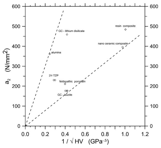
With Eq. (20) in mind, Fig. 13 shows a2 versus the inverse square root of H. a2 has units of N/mm2 or (Nm)/m3, whereas 1/√H has units of m/N0.5. Notwithstanding the mismatch in units, the variations in the techniques used to measure hardness, and the considerable scatter, there does seem to be a trend of increasing a2 with decreasing hardness. The data for the two filled resin composites, which are very soft, are in a different region in the plot.
Fig. 13.
Quadratic term a2 versus the inverse square root of hardness.
How do the indentation sizes compare to the chip distances? Fig. 1 shows some dramatic differences. Much greater plastic energy was expended during the edge chipping of the soft brittle polymer than for the hard 3Y-TZP.
If deformation processes dominate the edge chipping process, the a2 term in Eqs. (10) and (11) should dominate. This is confirmed by outcomes shown in Table 2, and Figs. 6, 7 and 9. The corresponding power law fit gives exponents between 1.6 and 1.8 for the lithium disilicate glass ceramic and the two filled-composite materials. In contrast, a material with high hardness and high fracture toughness, such as the 3Y-TZP, consumes much less energy in deformation, and most of the indenter work goes into fracture. The a1 term is more important, and the F–d trend is more linear as shown in Figs. 8 and 9.
So in summary, the quadratic force–distance function fits all of the data very well. Although it is a phenomenological model, the terms can be rationalized in terms of the indentation energy being partitioned between fracture and deformation processes. It is probably too much to expect a precise apportionment of indentation energy separately to fracture and deformation with exact correlations of GIc and H to the a1 and a2 terms. In real materials, the energies are probably mixed. For example, in materials which microcrack or promote crack deflection (such as the lithium disilicate glass ceramic), extensive microfracturing around the indentation may contribute more to the a2 volume deformation term than to the a1 fracture term. One advantage of the quadratic expression is that it is very versatile and can match both linear F–d and power law trends by simple shifts in the magnitudes of the a1 and a2 parameters. So it is not inconsistent with all the prior work [2–7,12] that has emphasized the linear trend, or the new indentation mechanics model with a power law of 1.5 [14].
Additional support for the simple phenomenological model proposed in this work may be found in the writings of one of the foremost authorities on hardness of materials, Prof. D. Tabor of the Cavendish Laboratory of the University of Cambridge, who wrote about cracking with spherical indenters: [55]
“…cracking is produced by a critical tensile stress. However, an energy balance must also be satisfied that is, the released elastic strain energy must be sufficient to provide for the surface energy involved in the production of the crack surfaces. This is the classic approach of fracture mechanics, and one of its consequences is a scaling effect: the released energy involves volume and is proportional to L3, where L is a linear dimension related to the size of the circle of contact, whereas the area of the crack is proportional to L2. Consequently, the smaller the indentation, the larger the stress (this determines the strain energy per unit volume) required to produce cracking. The formation and growth of the crack are also influenced by interfacial friction, differences in modulus between the indenter and specimen, and the presence of surface flaws.”
As the photos in this and Part 1 show, chip formation and detachment is a complex mixture of elastic, plastic, fracture and geometric processes. After nucleation and propagation, chips may either pop off abruptly or even be pried off the sides. The point here is that although edge chipping is a four-step process, the final chip event is a result of a roughly semicircular chip going unstable and popping off the side of the specimen. As such, and as Fig. 11 shows, fracture toughness, KIc, is the primary factor in controlling edge chipping resistance.
5. Conclusions
A new edge chipping equation that is based on a simple model is presented. All though phenomenological in approach, the model is based on the apportionment of indentation energy into fracture and deformation processes. Force–distance trends may vary from linear to nonlinear depending upon the material’s hardness, fracture toughness, and elastic modulus. Hard materials are more apt to have linear chipping behavior with most of the energy expended in fracture processes. Softer materials are more likely to have nonlinear chipping behavior with most of the energy consumed in deformation. Wedging stresses account for differences in edge chipping resistances measured with different indenters.
Supplementary Material
Acknowledgments
This work was made possible by a grant from NIH, R01-DE17983, and the people and facilities at the National Institute of Standards and Technology and the ADAF Paffenbarger Research Center. The authors wish to thank 3M-ESPE, St. Paul, MN, for donating materials for this study. This work is the logical extension of edge chipping started by Dr. Janet Quinn for her doctoral thesis at the University of Maryland in 1996–2000 and which she continued at the Paffenbarger Research Center. She was contemplating the significance and shortfalls of the power law function at the time of her untimely death in July 2008. We are sure that she eventually would have tried the quadratic function, since she had used it effectively with her hardness and brittleness work in the 1990s.
Appendix A. Supplementary data
Supplementary data associated with this article can be found, in the online version, at http://dx.doi.org/10.1016/j.dental.2014.02.014.
Footnotes
Commercial products and equipment are identified only to specify adequately the experimental procedures and does not imply endorsement by the authors, institutions or organizations supporting this work, nor does it imply that they are necessarily the best for the purpose.
Uncertainties in parenthesis are one standard deviation.
References
- 1.Quinn GD, Hoffman KH, Giuseppetti AA. Chipping fracture resistance of dental CAD/CAM restorative materials: Part 1. Procedures and results Dent Mater. 2014;30(5):99–111. doi: 10.1016/j.dental.2014.02.010. [DOI] [PMC free article] [PubMed] [Google Scholar]
- 2.McCormick NJ, Almond EA. Edge flaking of brittle materials. J Hard Mater. 1990;1(1):25–51. [Google Scholar]
- 3.McCormick NJ. Edge flaking as a measure of material performance. Met Mater. 1992;8:154–6. [Google Scholar]
- 4.Quinn JB, Su L, Flanders L, Lloyd IK. “Edge toughness” and material properties related to the machining of dental ceramics. Mach Sci Technol. 2000;4:291–304. [Google Scholar]
- 5.Morrell R, Gant AJ. Edge chipping of hard materials. Int J Refract Met Hard Mater. 2001;19:293–301. [Google Scholar]
- 6.Danzer R, Hangl M, Paar R. Edge chipping of brittle materials. In: Varner JR, Quinn GD, editors. Fractography of glasses and ceramics IV. Westerville, OH: American Ceramic Society; 2001. pp. 43–55. [Google Scholar]
- 7.Gogotsi G, Mudrik S, Galenko V. Evaluation of fracture resistance of ceramics: edge fracture tests. Ceram Int. 2007;33:315–20. [Google Scholar]
- 8.Watts DC, Issa M, Ibrahim A, Wakiga J, Al-Samadani K, Al-Azraqi M, et al. Edge strength of resin-composite margins. Dent Mater. 2008;24:129–33. doi: 10.1016/j.dental.2007.04.006. [DOI] [PubMed] [Google Scholar]
- 9.Baroudi K, Silikas N, Watts DC. Edge-strength of flowable resin-composites. J Dent. 2008;36:63–8. doi: 10.1016/j.jdent.2007.10.006. [DOI] [PubMed] [Google Scholar]
- 10.European prestandard, prTS 843-9. Advanced technical ceramics – mechanical properties of monolithic ceramics at room temperature, Part 9: Method of test for edge-chip resistance. Brussels: European Standard Committee TC; 2009. p. 184. [Google Scholar]
- 11.Quinn JB, Quinn GD, Hoffman KM. Edge chip fracture resistance of dental materials. Ceram Eng Sci Proc. 2012;33(2):71–84. [Google Scholar]
- 12.Quinn GD, Giuseppetti AA, Hoffman KH. Chipping fracture resistance of denture tooth materials. Dent Mater. 2014;30(5):545–53. doi: 10.1016/j.dental.2014.02.011. [DOI] [PMC free article] [PubMed] [Google Scholar]
- 13.Thouless MD, Evans AG, Ashby MF, Hutchinson JW. The edge chipping and spalling of brittle plates. Acta Metall. 1987;35(6):1331–41. [Google Scholar]
- 14.Chai H, Lawn BR. A universal relation for edge chipping from sharp contacts in brittle materials: a simple means of toughness evaluation. Acta Met. 2007;55:2555–61. [Google Scholar]
- 15.Clinton DJ, Morrell R. Hardness testing of ceramic materials. Mater Chem Phys. 1987;17:461–73. [Google Scholar]
- 16.McColm IJ. Ceramic hardness. New York: Plenum; 1990. [Google Scholar]
- 17.Bückle H. Progress in micro-indentation hardness testing. Metall Rev. 1959;4(13):49–100. [Google Scholar]
- 18.Quinn GD, Green P, Xu K. Cracking and the indentation size effect for knoop hardness of glasses. J Am Ceram Soc. 2003;86(3):441–8. [Google Scholar]
- 19.Swab JJ. Recommendations for determining the hardness of armor ceramics. Int J Appl Ceram Tech. 2004;1(3):219–25. [Google Scholar]
- 20.Swab JJ, Wereszczak AA, Pritchett J, Johanns K. Influence of microstructure on the indentation-induced damage in silicon carbide. Ceram Eng Sci Proc. 2006;27(3):251–9. [Google Scholar]
- 21.Li H, Bradt RC. The effect of indentation-induced cracking on the apparent microhardness. J Mater Sci. 1996;31:1065–70. [Google Scholar]
- 22.Yurkov AL, Breval E, Bradt RC. Cracking during indentation in Sialon-based ceramics: kinetic microhardness and acoustic emission. J Mater Sci Lett. 1996;15:987–90. [Google Scholar]
- 23.Gong J, Guan Z. Effect of microcracking on the energy-balance relationship for hardness testing of ceramics. Mater Lett. 2001;49:180–4. [Google Scholar]
- 24.Wilantewicz T, Cannon WR, Quinn GD. The indentation size effect (ISE) for Knoop hardness in five ceramic materials. Ceram Eng Sci Proc. 2006;27(3):237–49. [Google Scholar]
- 25.Rice RW, Wu CC, Borchelt F. Hardness-grain-size relations in ceramics. J Am Ceram Soc. 1994;7(10):2539–953. [Google Scholar]
- 26.Swain M, Wittling M. The indentation size effect for brittle materials: is there a simple fracture mechanics explanation? In: Bradt RC, Hasselman DPH, Munz D, Sakai M, Shevchenko VY, editors. Fracture Mechanics of Ceramics. Vol. 11. New York: Plenum Press; 1996. pp. 379–88. [Google Scholar]
- 27.Lysaght VE. Indentation hardness testing. New York: Reinhold Publishing Corp; 1949. [Google Scholar]
- 28.Hays C, Kendall EG. An Analysis of Knoop microhardness. Metallography. 1973;6:275–82. [Google Scholar]
- 29.Mott BW. Micro-indentation hardness testing. London: Butterworths; 1956. [Google Scholar]
- 30.Sargent PM. Use of the indentation size effect in microhardness for materials characterization. In: Blau P, Lawn B, editors. Microindentation techniques in materials science and engineering, ASTM STP 889. Philadelphia, PA: ASTM; 1986. pp. 160–74. [Google Scholar]
- 31.Sargent PM, Page TF. The influence of microstructure on the microhardness of ceramic materials. Proc Br Ceram Soc. 1987;26:209–24. [Google Scholar]
- 32.Bernhardt EO. On microhardness of solids at the limit of kick’s similarity law. Z Metallkd. 1941;33:135–44. [Google Scholar]
- 33.Mitsche R. Über die Eindringhärte Metallischer Fest und Lockerkörper. Osterr Chem Z. 1948;49:186. [Google Scholar]
- 34.Bückle H. Untersuchungen über die Lastabhängigkeit der Vickers-Mikrohärte. Z Metallkd. 1954;45:623–32. [Google Scholar]
- 35.Gong J, Li Y. An energy-balance analysis for the size effect in low-load hardness testing. J Mater Sci. 2000;35(1):209–13. [Google Scholar]
- 36.Hirao K, Tomozawa M. Microhardness of SiO2 glass in various environments. J Am Ceram Soc. 1987;70(7):497–502. [Google Scholar]
- 37.Fröhlich F, Grau P, Grellmann W. Performance and analysis of recording microhardness tests. Phys Status Sol A. 1977;42:79–89. [Google Scholar]
- 38.Li H, Bradt RC. The microhardness indentation load/size effect in rutile and cassiterite single crystals. J Mater Sci. 1993;28:917–26. [Google Scholar]
- 39.Li H, Ghosh A, Han YH, Bradt RC. The frictional component of the indentation size effect in low load hardness testing. J Mater Res. 1993;8(5):1028–32. [Google Scholar]
- 40.Quinn JB, Quinn GD. Indentation brittleness of ceramics: a fresh approach. J Mater Sci. 1997;32:4331–46. [Google Scholar]
- 41.Quinn JB, Quinn GQ. Hardness and brittleness of ceramics. Ceram Eng Sci Proc. 1996;17(3):59–68. [Google Scholar]
- 42.Yoo KC, Rosemeier RG, Elban WL. Armstrong, X-ray topography evidence for energy dissipation at indentation cracks in MgO crystals. J Mater Sci Lett. 1984;3:560–2. [Google Scholar]
- 43.Quinn GD, Melandri C, DePortu G. Edge chipping resistance of alumina/zirconia laminates. J Amer Ceram Soc. 2013;96(7):2283–91. [Google Scholar]
- 44.Toschi F, Melandri C, Pinasco P, Roncari E, Guicciardi S, DePortu G. Influence of residual stresses on the wear behavior of alumina/alumina-zirconia laminated composites. J Am Ceram Soc. 2003;86(9):1547–53. [Google Scholar]
- 45.Quinn JB, Quinn GD. Material properties and fractography of an indirect dental resin composite. Dent Mater. 2010;26(6):589–99. doi: 10.1016/j.dental.2010.02.008. [DOI] [PMC free article] [PubMed] [Google Scholar]
- 46.Technical Product Profile. 3M Paradigm™ MZ100 Block for CEREC®. St. Paul, MN: 3M Dental Products Brochure; 2000. [Google Scholar]
- 47.Shah MB, Ferracane JL, Kruzic JJ. R-curve behavior and toughening mechanism of resin-based dental composites: effects of hydration and post-cure heat treatment. Dent Mater. 2009;25:760–70. doi: 10.1016/j.dental.2008.12.004. [DOI] [PubMed] [Google Scholar]
- 48.Fischer-Cripps AF. Nanoindentation. 2. New York: Springer; 2004. [Google Scholar]
- 49.Cotterell B. Fracture and life. London: Imperial College Press; 2010. [Google Scholar]
- 50.Cotterell B, Kaminga J, Dickson FP. The essential mechanics of conchoidal flaking. Int J Fract. 1985;29:205–21. [Google Scholar]
- 51.Schwarzer N, Hermann I, Chdoba T, Richter F. Contact Modelling in the Vicinity of an Edge. Surf Coat Technol. 2001;146–147:371–7. [Google Scholar]
- 52.Samuels LE, Mulhearn TO. An experimental investigation of the deformed zone associated with indentation hardness impressions. J Mech Phys Sol. 1957;3:125–34. [Google Scholar]
- 53.Almond EA, McCormick NJ. Constant-geometry edge-flaking of brittle materials. Nature. 1986;321(6065):53–5. [Google Scholar]
- 54.Quinn JB, Ram Mohan VC. Geometry of edge chips formed at different angles. Ceram Eng Sci Proc. 2005;26(2):85–92. [Google Scholar]
- 55.Tabor D. Indentation hardness and its measurement: some cautionary comments. In: Blau P, Lawn BR, editors. Microindentation techniques in materials science and engineering. ASTM STP 889. West Conshohocken, PA: American Society for Testing and Materials; 1986. pp. 129–59. [Google Scholar]
Associated Data
This section collects any data citations, data availability statements, or supplementary materials included in this article.


