Abstract
The closure of a three-residue loop was studied using a developed kinematic method. It was shown that there are infinite number of three-residue loops (a locus of conformations), which can connect two segments of a polypeptide. This adds to the current understanding of a finite number of conformations for three-residue loop-closure. In the developed method, some of the equations can be solved analytically to reduce the computation cost. Benefiting from the reduced computation time, we determined all the relative positions of two polypeptide segments that can be connected by a three-residue loop.
Keywords: loop closure, loop conformation, kinematic method, dihedral angles
Introduction
Determining the conformation of amino acid residues in the loop connecting two segments of a protein secondary structure is essential in homology modeling as well as in modeling the dynamics of large scale conformational changes, such as those occurring during ion-channel gating. Prediction of loop structure is performed in two phases: determining all possible combinations of φ and ψ dihedral angles that keep the loop connected at both ends to the rest of the polypeptide (referred to as loop–closure problem),1–9 and selecting the most probable connected conformations.10–15 Determining the probable conformations is based on scoring the loop conformations according to their energy; it is not the topic of this study, which addresses the loop-closure problem.
Identification of connected loop conformations may be achieved by sampling the loop dihedral angles to determine the combinations of these angles that match the free end of the loop to its target location for loop closure.10,14,15 Fine sampling of the angles makes the computations extremely time consuming and expensive. Therefore, φ and ψ angles are usually sampled coarsely over the more probable regions of the Ramachandran plot16 to obtain approximate loop closure. In an approximate solution, the loose end of the loop is located close to its target location. Depending on the magnitude of error tolerance, there may be no exact solution in the vicinity of an approximate solution. Also, some exact solutions may be missed, because they are not in the vicinity of an approximate solution. Alternatively, analytical approaches, termed kinematic closure methods, have been used.1–4 In these approaches, trigonometric1 or polynomial2–4 equations for six dihedral angles (usually of three consecutive amino acid residues) are derived and solved numerically for any given combination of the remaining dihedral angles. This reduces the computation time significantly and enables a finer sampling of the remaining angles.
In this article, we first re-evaluate the closure of a three amino acid-residue loop and show that there is a continuous locus of conformations that closes the loop, rather than the commonly assumed finite number of up to 16 conformations. We then present a new kinematic closure technique that can predict this locus of conformations with less computation than existing kinematic closure methods.
Results
Loop-Closure Problem
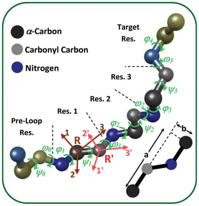
The loop-closure problem involves locating atoms of the loop residues, while preserving certain properties of the chemical bonds. Bonds lengths, bonds angles, and ω dihedral angle can vary over a small range and cannot account for large deformation of the loop; therefore, they are considered constant in this study. This means that the relative positions of atoms from one Cα to the next Cα are preserved. We term this preserved structure the backbone structure in this paper. In contrast, dihedral angles can vary over a large range, resulting in large deformations of the loop. The φ and ψ backbone dihedral angles are the significant degrees of freedom in the loop-closure problem.1 Figure 1 shows a three-residue loop that connects two segments of a polypeptide. Residues before and after the loop are termed preloop and target residues, respectively. In a three-residue loop-closure, given the φ and ψ angles of the preloop residue and the three residues in the loop, the location of N and Cα atoms of the target residue can be predicted. The loop closes properly if and only if these predicted locations coincide with the known locations of N and Cα atoms of the target residue. This results in six constraints (equations) for loop closure, as matching the location of each atom requires imposing three constraints (one for each coordinate). However, there is one degree of dependency between the locations of N and Cα of the target residue; the distance between these two atoms is constant. Therefore, there are five independent constraints (three coordinates of one atom and only two coordinates of the other atom).
Figure 1.
Backbone atoms of loop residues (Res. 1–3), preloop residue (Res. 0), and target residue (Res. 4) in a three-residue loop-closure problem. The φ and ψ dihedral angles of the residues are shown with green arrows. Two local coordinate systems are defined for each residue: the 1, 2, and 3 coordinates are located on α-carbon (R coordinate system), and the 1′, 2′, and 3′ coordinates on carbonyl carbon (R′ coordinate system).
Three-Residue Loop-Closure: A Continuous Locus of Solutions Rather than a Finite Number of Discrete Solutions
Different conformations of the three-residue loop backbone atoms are associated with different dihedral angles: ψ0, φ1, ψ1, φ2, ψ2, φ3, ψ3, and φ4. Note that the ω dihedral angles are 180° (or in rare cases 0°). Knowing the backbone locations of the preloop and target residues, there is one degree of dependency between these angles and only seven of them may be considered as independent degrees of freedom. For the loop closure, these dihedral angles should be subjected to five constraints. As the number of degrees of freedom is greater by 2 than the number of constraints, there are infinite number of conformations for a three-residue loop closure (if possible) and the associated dihedral angles form a continuous 2D locus in solution space. In considering ψ0 as a degree of freedom, it is implicitly assumed that the location of the oxygen atom of the preloop residue is adjustable as well. Arguing that this oxygen atom should maintain its location, ψ0 cannot be considered variable and there would be only 6 degrees of freedom, resulting in a 1D locus of solutions (There is 1 degree of freedom more than the number of constraints.).
In previously published studies,1–4 the number of constraints was considered 6 rather than 5, which led to determining a finite number of conformations for three-residue loops. In the method developed by Go and Scheraga,1 when defining the local coordinates and deriving the governing equations, it was implicitly assumed that the location of the Cα of the third loop residue is known. This location can vary along a circular path depending on the value of φ4. In the method developed later by Wedemeyer and Scheraga2 and Coutsias et al.,4 the problem was defined in terms of 3 degrees of freedom and three constraints. In this method, the possible conformations were also limited by assuming a fixed location for Cα of the third loop residue.
Governing Equations
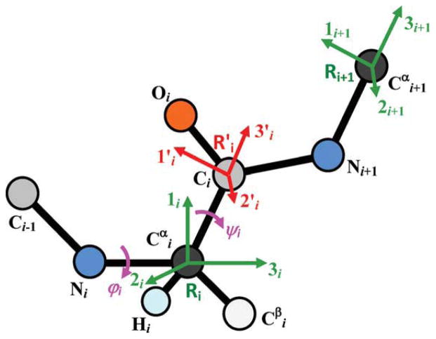
The three residues in the loop are labeled 1, 2, and 3, the residue before the loop (preloop residue) is labeled 0 and the residue after the loop (target residue) is labeled 4. Positions of residues 0 and 4 are fixed, and the goal is to determine the locations of the backbone atoms of residues 1, 2, and 3 so that these three residues connect residues 0 and 4. Knowing the position of residue 0, locations of all the backbone atoms of the loop residues can be determined in terms of ψ0, φ1, ψ1, φ2, ψ2, and φ3. Loop closure can be imposed by calculating locations of N and Cα of the forth residue in terms of theses dihedral angles and ψ3, and constraining them to the known locations of the fourth residue N and Cα. This approach imposes all the constraints on the peptide bond automatically during the calculation of the N and Cα locations. Instead of matching five coordinates of fourth residue N and Cα, we can match the location of one (three constraints) and the direction of the N—Cα bond (two constraints). In summary, the dihedral angles ψ0, φ1, ψ1, φ2, ψ2, φ3, and ψ3 should be selected such that the prediction for the location of Cα (termed location vector, Δ) and the direction of N—Cα bond (termed direction vector, r) of the fourth residue coincide with the known location and direction of the target residue (Fig. 2). To formulate the problem, we define a set of local coordinates for the loop residues. For each residue, two local coordinate systems are considered: R and R′ coordinate systems (Fig. 3). Center of the R coordinate system is located on Cα; its third axis is along the N—Cα bond and its first axis is on the surface that passes through N and Cα of the residue and the C of the previous residue. Center of the R′ coordinate system is located on C; its third axis is along the Cα—C bond and its first axis is in the surface that passes through N, Cα, and C.
Figure 2.
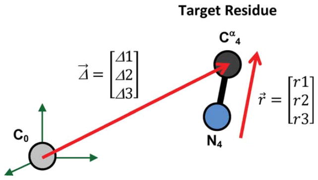
Position of N4 and Cα4 (N and Cα of the target residue) can be quantified in terms of the location of Cα4, presented by the Δ vector, and direction of the N4—Cα4 bond, presented by the r vector. Note that Δ has three independent components, but r has only two independent components as it is a direction vector and its magnitude is normalized to one. C0 is the carbonyl carbon of the preloop residue.
Figure 3.
Local coordinate systems R and R′ of the ith residue (Ri and ). 3i is along the bond, 1i is in the surface that passes through Ci−1, Ni, and . Similarly, 3′i is along bond and 1′i is in the surface that passes through Ni, , and Ci. Variation of φi changes the position of with respect to Ri. Variation of ψi changes the position of Ri+1 with respect to .
If we move along the loop residues from the preloop residue (residue 0) toward the target residue (residue 4), then variation of φi changes the location of Ci and the following residues but has no effect on Ri (the ith R coordinate system); it will change the relative position of (the ith R′ coordinate system) with respect to Ri. Also, variation of ψi has no effect on either Ri or ; it will change the relative position of Ri+1 with respect to . The relative position of any two of these local coordinate systems can be expressed by a rotational matrix and a displacement vector. The displacement vector is the relative location of the centers of the two coordinate systems. Because the backbone atoms of all the residues are similar, the relative rotation of local coordinates can be formulated in terms of two rotation matrices termed S and F. The F matrix transforms the coordinates of a vector in R′ to R; the S matrix transforms coordinates of a vector in R to the preceding R′. As explained above, the F matrix is a function of the φ angle, and the S matrix is a function of the ψ angle.
A spatial location can be transformed from to Ri through:
| (1) |
and from Ri + 1 to through:
| (2) |
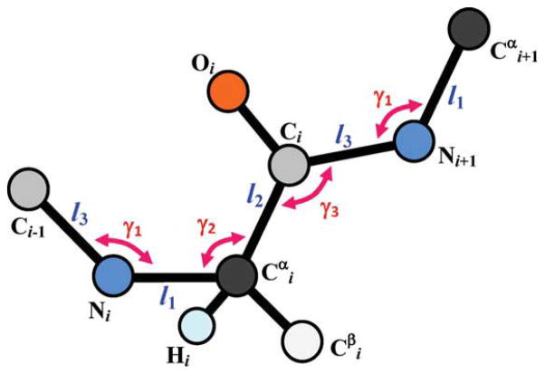
where d1 is the location of in and d2 is the location of Ci in Ri+1. d1 and d2 do not depend on the φ or ψ angles (Fig. 3). F, S, d1, and d2 can be determined in terms of bond lengths and bond angles that are shown in Figure 4. Assuming ω = 180°, we derived the rotation matrices as:
| (3) |
| (4) |
Figure 4.
Geometrical parameters of the polypeptide backbone that are required for determining the rotation matrices F and S, and the translation vectors d1 and d2.
Similar rotation matrices can be derived for the rare case of ω = 0°. For the ideal SP2 and SP3 orbital: γ1 = γ3 = 120°, γ2 = 109.5° and F(φ) and S(ψ) can be simplified as:
| (5) |
| (6) |
d1 and d2 are:
| (7) |
| (8) |
In this ideal case, the Cα—C bond is parallel to the N—Cα bond.9
To determine the required constraints (equations) for loop closure, we calculate the location of Cα4 and the direction of the N4—Cα4 bond in terms of the dihedral angles. We assumed that the location and direction of the target residue is given in the R′ coordinate system of the preloop residue (R′0) by Δ and r, respectively (Fig. 2). This coordinate system does not change with ψ0, φ1, ψ1, φ2, ψ2, φ3, and ψ3 and is the global coordinate in our problem. The location of Cα4 and the direction of N4—Cα4 in the R coordinate system of the target residue (R4) are: [0 0 0] and [0 0 1], respectively. We can transform this location and direction to the global coordinate system by consecutive transforms between the local coordinate systems:
| (9) |
| (10) |
As discussed in before, in a three-residue loop-closure problem there are seven variables (ψ0, φ1, ψ1, φ2, ψ2, φ3, and ψ3) and only five constraints. The two additional degrees of freedom lead to a 2D locus of solutions. We consider ψ0 and φ1 as free changing variables and calculate the values of ψ1, φ2, ψ2, φ3, and ψ3 that lead to a successful loop-closure for a given combination of ψ0 and φ1. Therefore, in eqs. (9) and (10), in addition to Δ and r, ψ0 and φ1 are known. Equations (9) and (10) may be rewritten as:
| (11) |
| (12) |
where
| (13) |
| (14) |
| (15) |
Note that the left sides of both eqs. (11) and (12) are known. For ideal orbital angles, eqs. (11) and (12) can be simplified to:
| (16) |
| (17) |
where
| (18) |
Both F and S are rotational matrices that when multiply a vector, do not change its magnitude. Therefore, the magnitude of the direction vector r should be normalized to one, as the magnitude of the right side of eq. (17) is one. Equation (17) imposes two constraints (it has only two independent equations) and eq. (16) imposes three constraints, providing together five equations for the five unknowns ψ1, φ2, ψ2, φ3, and ψ3. An interesting feature of eqs. (16) and (17) is that the system of five equations and five unknown is broken down to two systems: two equations and two unknowns in terms of α and β [eq. (17)], and three equations and three unknowns in terms of ψ1, ψ2, and ψ3 [eq. (16)]. This reduces the required computations significantly.
Defining r* as:
| (19) |
we may rewrite eq. (17) as:
| (20) |
| (21) |
| (22) |
Equation (22) can be solved analytically for β and substituting for β in eq. (20) or (21), α can be determined analytically as well.
Similarly defining Δ*as:
| (23) |
we may rewrite eq. (16) as:
| (24) |
| (25) |
| (26) |
If ψ1 is known, the two variables, ψ3 and ψ2, can be calculated analytically in terms of ψ1 via eqs. (24) and (25), respectively. Therefore, the numerical solution of these equations reduces to search for a ψ1 that satisfies eq. (26).
Analytical and Numerical Solutions of the Equations
Equations (20)–(22) can be solved analytically for α and β. β can be calculated from eq. (22) as:
| (27) |
Knowing that the term inside the parentheses in eq. (27) can only vary between −1 and +1, the acceptable range of for a successful loop-closure can be determined. Knowing β, we can calculate α using eq. (21) or (20). Note that these equations are not identical. Equations (20) and (21) can be rewritten as eqs. (28) and (29), respectively:
| (28) |
| (29) |
where
| (30) |
and
| (31) |
Given that the magnitude of r* is one, eqs. (28) and (29) are consistent. Although each of these equations has up to two solutions for α, only one solution satisfies both equations. Therefore, for each β calculated from eq. (27), α is calculated as:
| (32) |
There are up to two pairs of solutions for α and β. For each pair, eqs. (24)–(26) can be solved numerically to determine the three unknowns: ψ1, ψ2, and ψ3. These equations are linear in terms of six variables, the sin and cos of the three ψ angles. Values of the 3 sin terms can be determined in terms of the 3 cos terms, separately. For each cos term, there are two possible values for the sin term:
| (33) |
Therefore, eqs. (24)–(26) represents 23 = 8 different sets of three equations and three unknowns and have up to eight solutions for each pair of α and β. Consequently, loop closure has up to 16 solutions for the ideal SP2 orbital. Note that 16 is an upper bound for the number of solutions. Detailed analysis of the number of solutions in different regions of the variables domain (similar to what was performed by Milgram et al.9) is outside the scope of this article; it will be conducted as a separate study to further characterize our new approach.
We could not find analytical solutions for eqs. (24)–(26), however, similar to equations developed by Go and Scheraga,1 these equations can be simplified analytically into one equation in term of one angle. Here, we used (ψ1 − α) as the independent variable. A possible range of this angle was determined from eq. (24) and the cos(ψ1 − α) and sin(ψ1 − α) were computed for all the (ψ1 − α) angles within this range. cos ψ3 and, consequently, sin ψ3 were computed using eq. (24). Then, cos ψ2 and sin ψ2 were computed using eqs. (25) and (26), respectively. The function f(ψ1 − α) = cos2 ψ2 + sin2 ψ2 − 1 was then computed. The angles at which this function crosses zero are the solutions values of (ψ1 − α). We used very fine sampling of the ψ1 angle with 1 degree increments, which should capture solutions within ±0.5 degrees of the sampled values. This precision is sufficient for any practical application of loop closure, knowing that the stochastic fluctuations in dihedral angles are much larger than ±0.5 degrees.
Nonideal Bond Angles
Typically for protein structures, the angles γ1 and γ3 are slightly different than the ideal 120° considered in this formulations. Therefore, the term γ1 − γ3 may be nonzero and consequently eqs. (16) and (17) are not accurate. We calculated the joint probability distribution of these angles in the 3D structure of the Kv7.1 channel, which was derived previously17 based on homology to Kv1.2 with a known crystal structure in the open state.18 Considering only the five loop regions between consecutive transmembrane segments (in all four subunits), the average values of γ1 and γ3 are 120.7° and 117.2°, respectively, and their standard deviations are 2.8° and 1.3°, respectively. Figure 5 shows the joint probability distribution of γ1 and γ3 in the loop regions of Kv7.1 protein. The white line marks the backbone structures with parallel Cα—C and N—Cα bonds. Eight percent of the backbone structures have parallel bonds. In particular, the following residues had parallel bonds (within ±0.5°) in all four subunits: Thr153 (~118.3°) in S1–S2 loop, Phe193 (~117.5°) in S2–S3 loop, Ser217 (~116.9°) in S3–S4 loop, and Gly314 (~116.9°) in the loop between P-loop helix and S6. Also, the following residues had parallel bonds in at least two subunits: Val141, Thr144, and Asp 317. The backbone with γ1 = 120° ± 0.5° and γ3 = 117° ± 0.5° is the most probable structure, with a probability of about 8% as well. In the following, we present a method to determine the loop closure φ and ψ dihedral angles for a backbone structure with nonparallel bonds, using the dihedral angles computed for the backbone structure with parallel bonds as a starting point.
Figure 5.
Joint probability distribution of the of two consecutive γ1 and γ3 bond angles in the loop regions of the Kv7.1 ion-channel protein. The white line marks the backbone structures with γ1 = γ3. [Color figure can be viewed in the online issue, which is available at wileyonlinelibrary.com.]
Equations (11) and (12) may be written in the general form of:
| (34) |
Assume Ψi = [ψ1i φ2i ψ2i φ3i ψ3i]T is the (exact) solution of eqs. (16) and (17) (the ideal case where γ1 = γ3) for a given direction and location of a target residue given by . This would be an approximate solution of eqs. (11) and (12) where γ1 ≠ γ3 (nonideal case). Assume is the location and direction of the target residue for Ψi dihedral angles (ideal solution which serves as an approximate solution for the nonideal case) when the loop consists of three residues with nonideal backbone structures. Li is deflected from the desired location and direction by δL = L − Li.
We can linearize equation set (34) in the vicinity of the approximate solution using the Jacobean matrix, J:
| (35) |
where,
| (36) |
Given that γ1 − γ3 is small, the solution of eqs. (11) and (12) can be derived through eq. (35) as:
| (37) |
If the Jacobean matrix is close to singular and its inverse consists of relatively large elements, we may need to use an intermediate backbone structure. The solutions of the intermediate structure will be computed using solutions of the parallel structure as initial estimates. These intermediate solutions can then be used as initial estimates to compute the solutions of the desired structure.
Example of Application
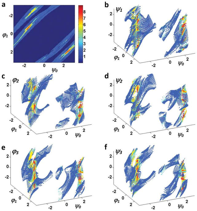
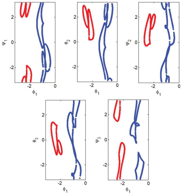
As an example, we determine all possible conformations of a three-residue loop for connecting two segments of a polypeptide when the location of the target Cα is Δ = [8, 2, 3]0′ angstrom and the direction of the N—Cα bond is r = [0.8, 0 – 0.6]0′ in R′0. Figure 6 shows the 2D locus of all possible loop dihedral angles determined using the new method. ψ0 and φ1 are the free changing variables and ψ1, φ2, ψ2, φ3, and ψ3 are calculated via eqs. (16) and (17) for any given ψ0 and φ1 (if possible). The number of possible loop conformations for each combination of the ψ0 and φ1 angles are shown in Figure 6A. The resultant loop conformations along the ψ0 = −1 path form a 1D locus (Fig. 7) and are visualized in two movies (Supporting Information Movies M1 and M2).
Figure 6.
2D locus of loop dihedral angles for the location vector [8,2,3] and direction vector [0.8,0.0,−0.6]. (a) The number of solutions at each combination of ψ0 and φ1 and (b–f) are ψ1, φ2, ψ2, φ3, and ψ3 angles, respectively, for different choices of ψ0 and φ1. [Color figure can be viewed in the online issue, which is available at wileyonlinelibrary.com.]
Figure 7.
1D locus of the dihedral angles ψ1, φ2, ψ2, φ3, and ψ3 in terms of the free changing variable φ1 when ψ0 = −1 in Figure 6. The locus consists of two closed curves colored blue and red. Note that as π and −π are the same angles the top and bottom of each panel is connected. Supporting Information Movies M1 and M2 are associated with the red and blue curves, respectively.
Table 1 provides the numerical values (in degrees) of the eight solutions computed for eqs. (16) and (17) (ideal backbone structure) when ψ0 = −π/4 and φ1 = −π/2. For a nonideal backbone structure with γ1 = 120.7° and γ3 = 117.2°, using the ideal case dihedral angles of Table 1 results in 3% and 2% average error in matching the direction and location of the target residue. The eight accurate solutions for this nonideal backbone structure were computed using eq. (37) and are presented in Table 2.
Table 1.
Example of Application in the Ideal (γ1 = γ3) Case.
| Set 1 | Set 2 | Set 3 | Set 4 | Set 5 | Set 6 | Set 7 | Set 8 | |
|---|---|---|---|---|---|---|---|---|
| ψ1 | 122.2 | −156.7 | 101.7 | −176.2 | 25.6 | −97.3 | 14.1 | −68.9 |
| φ2 | −54.3 | −135.4 | −33.8 | −115.9 | 42.3 | 165.2 | 53.8 | 136.8 |
| ψ2 | 142.0 | 173.4 | 51.4 | 52.1 | −128.2 | 126.0 | −37.0 | −71.0 |
| φ3 | 142.1 | 110.7 | −127.2 | −127.9 | 52.3 | 50.1 | −38.8 | −4.8 |
| ψ3 | −124.9 | −43.7 | 145.1 | 63.5 | −136.8 | −12.2 | 125.4 | 42.3 |
The eight sets of dihedral angles for the loop-closure when ψ0 = −π/4, φ1 = −π/2, and γ1 = γ3 = 120°. The target residue is located at Δ = [8,2,3]0′ along direction r = [0.8,0, −0.6]0′.
Table 2.
Example of Application in the Nonideal (γ1 ≠ γ3) Case.
| Set 1 | Set 2 | Set 3 | Set 4 | Set 5 | Set 6 | Set 7 | Set 8 | |
|---|---|---|---|---|---|---|---|---|
| ψ1 | 128.9 | −156.0 | 113.9 | −173.6 | 25.4 | −83.5 | 22.3 | −69.7 |
| φ2 | −61.4 | −140.3 | −45.1 | −122.6 | 47.6 | 150.7 | 50.7 | 137.9 |
| ψ2 | 122.9 | 154.0 | 60.4 | 72.9 | −103.7 | −116.3 | −54.4 | −90.5 |
| φ3 | 160.2 | 130.8 | −140.5 | −152.5 | 29.1 | 42.2 | −22.7 | 15.4 |
| ψ3 | −129.7 | −29.7 | 155.2 | 54.1 | −150.4 | 5.8 | 145.2 | 33.3 |
The eight sets of dihedral angles for the loop-closure when ψ0 = −π/4, φ1 = −π/2, γ1 = 120.7° and γ3 = 117.2°. The target residue is located at Δ = [8,2,3]0′ along direction r = [0.8,0, −0.6]0′.
Over What Distance Can a Three-Residue Loop Connect Two Polypeptide Segments?
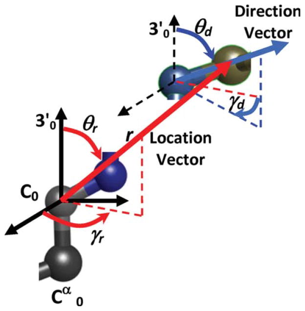
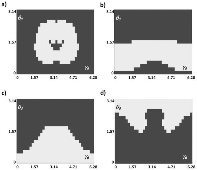
Using this new method, we were able to solve the loop-closure problem for different locations and directions of the target residue and determine over what maximum distance a three-residue loop can connect two segments of a polypeptide. For this purpose, we define the location of the target Cα in a spherical coordinate system in terms of r, θr, and γr (Fig. 8). Both γr and ψ0 are rotations about the same axis; any change in γr leads to an equal change in ψ0 values of the solutions. Therefore, without loss of generality, we can set γr to zero. The direction of N—Cα can be defined in terms of two angles θd and γd (Fig. 8). γd is the rotation of the direction vector about the 3′0 axis with respect to the location vector, and θd is the angle between the direction vector and the 3′0 axis. Figure 9 shows possible locations of the target Cα for three-residue loops. For any possible location of target Cα, only a fraction of target N—Cα directions lead to a successful loop closure. These fractions are shown by different colors in the figure; if Cα is located about 7–10Å from the carbonyl carbon of the preloop residue at an angle between 0 and π/2, loop closure is possible for about 50% of the target directions. The possible directions are different for different locations as shown in Figure 10. The location associated with each panel of Figure 10 is marked by the same letter in Figure 9.
Figure 8.
Direction vector and location vector of the target residue and their characteristic parameters.
Figure 9.
Possible locations of the target Cα. The percentage of possible directions at each location is shown by its color. a–d mark indicate four arbitrary locations of Cα.
Figure 10.
Possible directions (white area) of the target N—Cα at four arbitrary locations a–d (shown in respective panels) of the target Cα. Locations correspond to those marked in Figure 9.
Comparison of the Computation Time with the Polynomial Method
The computational efficiency of this method was compared with the widely accepted polynomial method developed by Coutsias et al.,4 based on the initial formulation of Wedemeyer and Scheraga.2 In the polynomial method,4 the relative positions of the two segments of a polypeptide are characterized by three angles: α1 (or alternatively α2), ξ3, and η3, and the loop conformation can be determined by solving the constraints for three variable angles: τ1, τ2, and τ3. These parameter sets are different than the kinematic approach developed in this paper. To have a fair comparison, we generated about 3500 different loop-closure problems for each method by choosing different combinations of the α1, ξ3, and η3 in the polynomial method, and different combinations of r, θr, θd, and γd in the kinematic method presented here. Using polynomial method, we solved the generalized eigenvalue formulation of the problem using the efficient built-in function of the MATLAB software (based on QZ factorization). The C.P.U. time was measured (10 times) for each method and divided by the number of loop-closure problems solved, to find the average computing time per loop-closure problem. Table 3 compares the mean and standard deviation of the computing time per loop-closure problem for the kinematic method of this article and the polynomial method. The kinematic method of this article, on average, is about 15 times faster than the polynomial method.
Table 3.
Comparison of Computation Time per Loop Between the Kinematic Method of This Article and the Polynomial Method.
| C.P.U. time per loop | Mean | Standard deviation |
|---|---|---|
| New kinematic (this article) | 4.7 × 10⁻⁵ s | 4.4 × 10⁻⁶ s |
| Polynomial (ref. 4) | 7.2 × 10⁻⁴ s | 6.7 × 10⁻⁶ s |
Multiplicity of solutions is taken into account in calculating the average computing time per loop closure problem, which considers all possible solutions (up to 16). In the supplementary MATLAB code used for these computations, all eight equation sets were solved for each loop-closure problem and the average computing time was determined for the entire loop-closure problem with multiple solutions.
Discussion
Determining all possible loops that can connect two segments of a protein secondary structure is important for analysis of protein folding and of large conformational changes of the folded protein. The energy levels among all possible connecting loops can vary by several kT (k is the Boltzmann constant and T is the absolute temperature), and consequently, the probability of the associated protein folded structure can vary by orders of magnitude. Therefore, selecting a limited number of loop conformations by trial and error or underestimating the number of possible loop conformations (up to 16 discrete conformations rather than a 2D continuous locus of conformations) may lead to significant inaccuracy in estimating the likelihood of the folded structure.
The kinematic closure technique derived here for three-residue loops is applicable to two residue loops as well. In two residue loops, the number of constraints and degrees of freedom is 5, and therefore, instead of a 2D locus, there is a finite number of conformations. For one residue loops, the number of degrees of freedom is less than the number of constraints (three degrees of freedom and five constraints); in this case, a solution exists if the five constraint equations can be reduced to three (or less) independent equations. If the number of residues in a loop is greater than three, they may be grouped into several three residue segments, and possibly an additional single residue or double residue segment, and the equations for each group may be solved independently.
The kinematic closure technique of this article (similar to many others) limits the degrees of freedom to the φ and ψ dihedral angles and assumes that the bond lengths and bond angles are constant and the ω dihedral angle is 180°. However, in actual protein structures the bond angles (e.g., γ1, γ2, and γ3) and ω dihedral angle may vary by about ±5°, and the bond lengths may vary by about ±0.01 Å. The position of the target residue may be altered slightly by changing the angles within ±5°, but would not change significantly by changing the lengths within ±0.01 Å. Including the four additional bond angles as degrees of freedom will increase computation greatly. For example, if we consider only five possibilities for each of these angles, we need to find the φ and ψ dihedral angles for 54 = 625 different backbone structures. Given the limited range of these angles, the resultant dihedral angles and consequently the loop conformations will be close to each other (for each solution of the loop closure). To determine the loop conformations that can connect two segments of a polypeptide (if any), we choose one of the probable backbone structures and determine the closed loop conformations for that backbone structure. Each resultant loop conformation is representative of a family of closely positioned conformations with slightly perturbed backbone structures. For the Kv7.1 ion-channel protein structure, we found that backbone structures with parallel bonds (γ1 = γ3) are a good choice, as it accounts for about 8% of all backbone structures and requires less computation than the nonparallel bond structures. Note that the probability of the most probable backbone structure is also about 8% (Fig. 5), so the parallel bonds structures (ideal) are not far from the physiological condition.
Supplementary Material
Acknowledgments
Contract/grant sponsor: National Institutes of Health-National Heart, Lung and Blood Institute; contract/grant number: R01-HL 049054-18; contract/grant number: R01-HL 033343-26
Contract/grant sponsor: Children’s Discovery Institute Fellowship; contract/grant number: CH-F-2008-121
Many thanks to colleagues in the Rudy Lab and to Dr. Niloufar Ghoreishi for help, advice, and discussions. Y.R. is the Fred Saigh Distinguished Professor at Washington University in St. Louis. Figures 1 and 8 and Supporting Information movies were produced using the UCSF Chimera package (Chimera package was supported by NIH grant P41 RR-01081).
Footnotes
Additional Supporting Information may be found in the online version of this article.
References
- 1.Go N, Scheraga HA. Macromolecules. 1970;3:178. [Google Scholar]
- 2.Wedemeyer WJ, Scheraga HA. J Comput Chem. 1999;20:819. doi: 10.1002/(SICI)1096-987X(199906)20:8<819::AID-JCC8>3.0.CO;2-Y. [DOI] [PubMed] [Google Scholar]
- 3.Mandell DJ, Coutsias EA, Kortemme T. Nat Methods. 2009;6:551. doi: 10.1038/nmeth0809-551. [DOI] [PMC free article] [PubMed] [Google Scholar]
- 4.Coutsias EA, Seok C, Jacobson MP, Dill KA. J Comput Chem. 2004;25:510. doi: 10.1002/jcc.10416. [DOI] [PubMed] [Google Scholar]
- 5.Dodd LR, Boone TD, Theodorou DN. Mol Phys. 1993;78:961. [Google Scholar]
- 6.Manocha D, Canny JF. IEEE Trans Rob Autom. 1994;10:648. [Google Scholar]
- 7.Wu MHG, Deem MW. J Chem Phys. 1999;111:6625. [Google Scholar]
- 8.Dinner AR. J Comput Chem. 2000;21:1132. [Google Scholar]
- 9.Milgram RJ, Liu GF, Latombe JC. J Comput Chem. 2008;29:50. doi: 10.1002/jcc.20755. [DOI] [PubMed] [Google Scholar]
- 10.Felts AK, Gallicchio E, Chekmarev D, Paris KA, Friesner RA, Levy RM. J Chem Theory Comput. 2008;4:855. doi: 10.1021/ct800051k. [DOI] [PMC free article] [PubMed] [Google Scholar]
- 11.Ginalski K. Curr Opin Struct Biol. 2006;16:172. doi: 10.1016/j.sbi.2006.02.003. [DOI] [PubMed] [Google Scholar]
- 12.Hornak V, Simmerling C. Proteins. 2003;51:577. doi: 10.1002/prot.10363. [DOI] [PubMed] [Google Scholar]
- 13.Hu XZ, Wang HC, Ke HM, Kuhlman B. Proc Natl Acad Sci USA. 2007;104:17668. doi: 10.1073/pnas.0707977104. [DOI] [PMC free article] [PubMed] [Google Scholar]
- 14.Jacobson MP, Pincus DL, Rapp CS, Day TJF, Honig B, Shaw DE, Friesner RA. Proteins. 2004;55:351. doi: 10.1002/prot.10613. [DOI] [PubMed] [Google Scholar]
- 15.Sellers BD, Zhu K, Zhao S, Friesner RA, Jacobson MP. Proteins. 2008;72:959. doi: 10.1002/prot.21990. [DOI] [PMC free article] [PubMed] [Google Scholar]
- 16.Ramachandran GN, Ramakrishnan C, Sasisekharan V. J Mol Biol. 1963;7:95. doi: 10.1016/s0022-2836(63)80023-6. [DOI] [PubMed] [Google Scholar]
- 17.Silva JR, Pan H, Wu D, Nekouzadeh A, Decker KF, Cui J, Baker NA, Sept D, Rudy Y. Proc Natl Acad Sci USA. 2009;106:11102. doi: 10.1073/pnas.0904505106. [DOI] [PMC free article] [PubMed] [Google Scholar]
- 18.Long SB, Campbell EB, Mackinnon R. Science. 2005;309:897. doi: 10.1126/science.1116269. [DOI] [PubMed] [Google Scholar]
Associated Data
This section collects any data citations, data availability statements, or supplementary materials included in this article.


