

Abstract
Fe(I) centers in iron-sulfide complexes have little precedent in synthetic chemistry despite a growing interest in the possible role of unusually low-valent iron in metalloenzymes that feature iron-sulfur clusters. A series of three diiron (L3Fe)2(μ-S) complexes that can be isolated and characterized in the low-valent oxidation states Fe(II)-S-Fe(II), Fe(II)-S-Fe(I), and Fe(I)-S-Fe(I) is described. This family of iron sulfides constitutes a unique redox series comprising three nearly isostructural but electronically distinct Fe2(μ-S) species. Combined structural, magnetic, and spectroscopic studies provide strong evidence that the pseudotetrahedral iron centers undergo a transition to low-spin S = 1/2 states upon reduction from Fe(II) to Fe(I). The possibility of accessing low-spin, pseudotetrahedral Fe(I) sites compatible with S2− as a ligand was previously unknown.
Keywords: iron(I), iron-sulfur clusters, FeS, hydrogenase, nitrogenase
Fe-S-Fe linkages are common to a host of metalloenzymes that mediate metabolic transformations central to life. Iron sulfur clusters composed of these linkages frequently perform roles associated with electron transfer and redox processes[1] and research into the synthesis and characterization of model complexes of these clusters featuring Fe(II) and Fe(III) has been an area of intense study.[2] Holm pioneered the synthesis of Fe-S clusters featuring exclusively Fe(II) centers.[3] However, while unusually low formal oxidation states of Fe (e.g., Fe(I) and Fe(0)) have been implicated in the function of hydrogenase and nitrogenase enzymes where bridging sulfur may be present,[4–5] low valent Fe species bound to two-coordinate sulfide are without ample precedent in synthetic coordination chemistry. It is therefore of interest to understand whether the sulfide structural unit is compatible with unusually low-valent Fe centers, and if so, what electronic structures and reactivity patterns might be expected.
In this context, Holland and coworkers recently reported the singular example of a synthetic complex featuring Fe(I) centers ligated to sulfide (S2−) by the reduction of {[HC(CMeN[2,6-diisopropylphenyl])2]Fe}2{μ-S} to a doubly reduced diiron(I) species.[6] Our laboratory has also had an interest in the study of unusually low-valent Fe-X-Fe linkages, for example where the bridging X unit is either imide (NH2−) or nitride (N3−).[7] Herein, we describe a series of diiron Fe2(μ-S) complexes in the formal oxidation states Fe(II)-S-Fe(II), Fe(II)-S-Fe(I), and Fe(I)-S-Fe(I) (Scheme 1). This family of Fe sulfide complexes constitutes a unique set of three isolable and nearly isostructural, but electronically distinct, low-valent Fe2(μ-S) species. Additionally, combined structural, magnetic, and spectroscopic studies provide strong evidence that the Fe centers undergo a transition to low-spin S = 1/2 states upon reduction. The possibility of accessing low-spin, pseudotetrahedral Fe(I) sites compatible with S2− as a ligand was previously unknown.
Scheme 1.
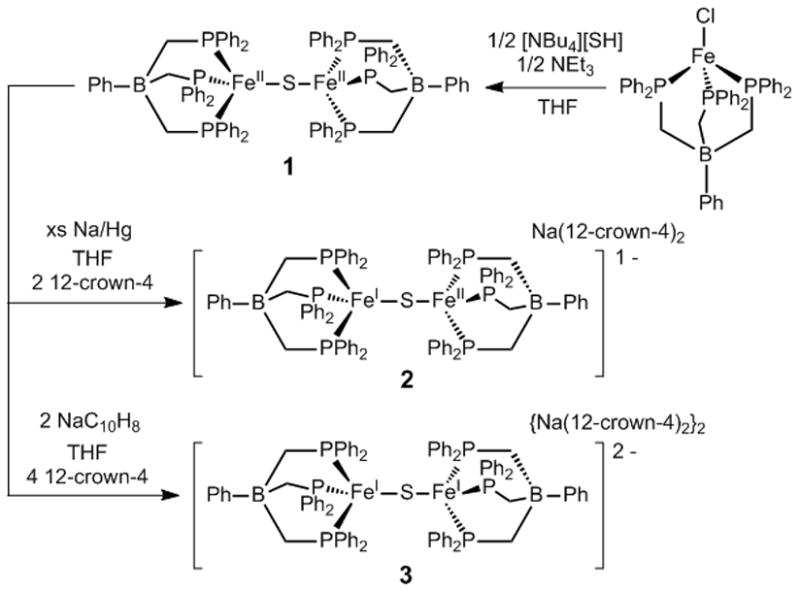
Synthesis of an [(L3Fe)2(μ-S)]n− redox series (n = 0, 1, 2).
Use of [NBu4][SH] as a sulfur source allows for the synthesis of ([PhBP3]Fe)2(μ-S) (1) as a dark brown powder in moderate yield (51% isolated, Scheme 1) from the chloride precursor [PhBP3]FeCl ([PhBP3] = [PhB(CH2PPh2)3]).[8] The cyclic voltammogram of 1 (See SI) displays two reversible reductions that are assigned as the Fe(II)Fe(II)/Fe(II)Fe(I) and Fe(II)Fe(I)/Fe(I)Fe(I) couples at −1.52 V and −2.30 V vs. Fc/Fc+, respectively. Chemical reduction of 1 with Na/Hg amalgam results in a color change from dark brown to a deep green. Addition of 12-crown-4 and crystallization provides {([PhBP3]Fe)2(μ-S)}{Na(12-crown-4)2} (2) as a nearly black solid in 76% isolated yield. When 1 is instead exposed to 2 equivalents of NaC10H8 an almost black solution results which can be treated with 12-crown-4 and crystallized in an analogous manner to yield {([PhBP3]Fe)2(μ-S)}{Na(12-crown-4)2}2 (3) as a black solid in 49% isolated yield.
Species 1, 2, and 3 afford an unusual isolable redox series and hence more thorough characterization including single crystal XRD studies was undertaken (Figure 1). The Fe-S bond lengths in 1–3 are short when compared with previously reported Fe-S bond lengths for bridging sulfides (avg. 2.22 Å).[9] In fact, the Fe-S bond length of 2.071(1) Å in 3 is within error the shortest bond between Fe and sulfide reported in the CSD, with a close value of 2.078(8) Å for [Fe2S2(C4H4N)4][NBu4]2 reported by Coucouvanis et al.[10] The short Fe-S distances in 1–3 suggest an appreciable amount of multiple bonding between Fe and S as has been observed in other linear sulfide bridged complexes of mid to late first row transition metals.[11] The Fe-S bond distances in 1, 2, and 3 differ only by 0.032 Å, suggesting little perturbation of the bonding in the Fe-S-Fe manifold upon reduction.
Figure 1.
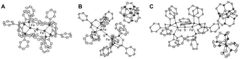
XRD structures of complexes 1–3 (A, B, and C respectively) shown with ellipsoids at 50% probability and hydrogens omitted for clarity.
All three complexes display nearly, or perfectly in the case of 1, linear Fe-S-Fe bond angles. Fe-S-Fe linkages are more typically bent as in the example by Coucouvanis.[10] The sterics of [PhBP3] allow for a significantly bent Fe-X-Fe angle as exemplified in a structurally related Fe2(μ-N) nitride complex previously characterized by our laboratory.[7] This fact suggests an electronic origin to the linearity of the Fe-S-Fe linkages in 1–3. While the bond distances in 1 are consistent with previously synthesized high spin phosphine ligated Fe(II) complexes from our laboratory,[8,12] a contraction of 0.22 Å in the average Fe-P bond lengths is apparent upon reduction from 1 to 3 resulting in an unusually short average Fe-P bond distance of 2.17 Å in 3 (The average Fe-PR3 distance from the CSD is 2.24 Å).[9] Increased back-bonding into the phosphines would explain some contraction in these lengths, but the magnitude of the change suggests that there may be additional factors involved such as a spin state change. To probe this possibility, variable temperature magnetic susceptibility data on 1–3 were acquired via SQUID magnetometry.
At room temperature, complex 1 displays a magnetic moment of 2.0 μB which is much smaller than the spin-only value of 6.9 μB that is predicted for two non-interacting high spin Fe(II) centers.[13] The variable temperature magnetic susceptibility data for 1 from 2–300 K are shown in Figure 2 and show a decrease in the magnetic moment upon cooling. This phenomenon is consistent with antiferromagnetic coupling between the two Fe centers and a simulation with a coupling constant of J = −154 cm−1 provides a reasonable fit to the data (Figure 2). Antiferromagnetic coupling via a linear 1-atom bridge is common and this behavior has been observed in other Fe-S-Fe complexes.[6b,14]
Figure 2.

(A) Variable temperature magnetic susceptibility data for 1–3 at a field of 0.5 T and fits shown as solid lines with the parameters shown in the SI. (B) 80 K Mössbauer data for 1–3 and fits shown as solid lines with parameters shown in the SI.
In contrast to 1, 2 displays a high magnetic moment of 5.8 μB at 300 K and this moment remains nearly constant upon cooling to ~50 K before dropping at lower temperatures, presumably due to intermolecular antiferromagnetic interactions. For a high-spin S1 = 2 and S2 = 3/2 case the spin only moment for two non-interacting Fe centers is 6.2 μB,[13] higher than observed for 2 above 50 K. Antiferromagnetic coupling seems unlikely, as the magnetic moment does not decrease upon cooling. An S = 1/2 ground state would also be expected from an antiferromagnetically coupled system but the X-band EPR spectrum of 2 at 4 K (SI) shows a strong feature located near g = 5, inconsistent with an S = 1/2 ground state. Correspondingly, fits of the magnetic susceptibility for an S1 = 2 and S2 = 3/2 state with even modest negative values of J provide very poor fits to the data (See SI). The 300 K moment of 5.8 μB is near the spin only value of one S = 5/2 center (5.9 μB) suggesting that either an S1 = 2 and S2 = 1/2 or an S1 = 1 and S2 = 3/2 spin state assignment with strong ferromagnetic coupling between the two metal centers could be an appropriate model. Simulations using either of these spin state descriptions can provide a good fit to the susceptibility data (Figure 2, SI). For the additional reasons given below, we prefer an S1 = 2 and S2 = 1/2 assignment for 2 with J = 100 cm−1.
An increase in magnetic moment is typically observed upon cooling in ferromagnetic systems.[13] This results from an increase in the population of higher spin-states as the temperature is lowered At sufficiently large ferromagnetic couplings, a high spin ground state becomes thermally well separated from lower-spin excited states and a plateau in the moment is observed. Such behavior has been observed in other strongly coupled systems.[15] The large coupling in 2 is thus in accord with the relatively temperature independent profile of its magnetic moment above 50 K. It should also be noted that while the fit of the susceptibility data of 2 requires the coupling constant to be large and positive, the magnitude of J is sensitive to minor perturbations in the fit and diamagnetic correction, implying substantial uncertainty in the value of J. The presence of coupling between the two Fe centers in 2 is further corroborated by an intervalence charge-transfer (IVCT) band at 6750 cm−1 in the near-IR spectrum of 2. Analysis of this band (SI) suggests that 2 is well described as a Class II mixed-valence species via the Robin-Day classification scheme.[16]
The variable temperature magnetic data for complex 3 also display a nearly flat moment upon cooling from 300 K to 50 K. A similar analysis to that performed for 2 suggests that the high-spin S1 = S2 = 3/2 case should show a spin only value of 5.5 μB for uncoupled Fe centers, much larger than that observed. If one assumes a low-spin configuration at both Fe centers and a ferromagnetic coupling constant of J = 110 cm−1 a satisfactory fit to the magnetic data is obtained. The assignment of 3 as a ferromagnetically coupled low-spin Fe(I)/Fe(I) complex suggests by extension that the assignment of 2 as an S1 = 2 and S2 = 1/2 species is plausible and is perhaps the best model of those we have considered. Such a low-spin assignment for 2 (and 3), while highly unusual for an iron-sulfide complex, seems to us plausible by comparison with previous examples of low-spin pseudotetrahedral L3CoIIX complexes of the same tris-phosphine ligand scaffold.[17]
We turned to Mössbauer spectroscopy to further probe the Fe sites in 1–3 (Figure 2B). Complex 1 shows a quadrupole doublet (80 K) with an isomer shift of δ = 0.49 mm/s and a quadrupole splitting of ΔEq = 1.91 mm/s. These values are similar to data for related tris-phosphine Fe(II) complexes reported by our laboratory.[18] Upon reduction to 2 the quadrupole doublet shifts slightly to δ = 0.47 mm/s and contracts to ΔEq = 1.14 mm/s. Additionally a new feature in a 1:1 ratio with the doublet appears in the spectrum at δ = 0.16 mm/s which can be fit with an almost negligible quadrupole splitting of ΔEq = 0.01 mm/s. The two Fe sites in 2 are hence well resolved on the Mössbauer timescale. The Mössbauer spectra of 3 shows a single broad feature centered at δ = 0.22 mm/s with quadrupole splitting that is too small to be resolved. Fe(I) complexes structurally related to 2 and 3 that have been previously characterized by Mössbauer spectroscopy, for example [PhBP3]Fe(PMe3), are high spin, and have parameters that do not agree well with those obtained for the reduced sites in 2 and 3, suggesting distinct electronic structures for the present case.[18] One most typically observes an increase in isomer shift δ upon reduction of an Fe system, in contrast to the trend observed for 1–3.[19] The negative shift that is instead observed presumably results from the high covalency present in these low-valent (L3Fe)2(μ-S) cores.
The collection of data presented suggest that upon reduction of the high spin Fe2(μ-S) complex 1 to 2, a reduced Fe(I) center results that populates a low spin S = 1/2 state instead of an S = 3/2 state akin to the Fe sites in Holland’s diiron(I) sulfide system.[6] Further reduction to 3 provides two low-spin d7 Fe(I) centers that ferromagnetically couple. In addition to the susceptibility data presented, these conclusions are supported by the substantially shortened Fe-P bond distances observed upon successive reductions. The Mössbauer data collected on 1–3 are also consistent with this model, showing values consistent with high-spin Fe(II) centers for complex 1 but new features that are distinct from previously reported high-spin Fe(I) complexes of similar geometries supported by the [PhBP3] ligand auxiliary.
The magnetic data associated with complexes 1–3 and the unusual observation of low spin, tetrahedral Fe(I) sites within an (L3Fe)2(μ-S) system deserves some additional comment. Analysis of a qualitative d-orbital splitting diagram with no explicit coupling depicted helps to suggest an array of coupling interactions imposed by the spin state change that may account for the observed magnetic behavior (Figure 3). In complex 1, antiferromagnetic exchange is expected to occur through both the σ and π manifolds via the half populated dz2 and dxz,yz orbitals. Upon reduction, and double population of one dz2 orbital arising from a transition to a low-spin d7 center, the coupling interaction mediated through the σ manifold, which should dominate, instead becomes ferromagnetic. Upon further reduction to 3, the σ manifold becomes completely filled as a result of two low-spin d7 centers. A ferromagnetic interaction is observed and results from the π manifold as required by Hund’s rule.[20] While speculative, this orbital picture provides a simple intuitive explanation for the observed magnetism in 1–3. Further work including theoretical calculations and variable field magnetic studies are warranted to more fully understand this electronically unusual iron-sulfide series.
Figure 3.

Qualitative d-orbital splitting diagrams illustrating the orbitals involved in coupling in complexes 1–3.
Supplementary Material
Table 1.
Selected bonding metrics for complexes 1–3.
| Complex | Fe-S (Å) | Fe-S-Fe (°) | Avg. Fe-P (Å) | Δ Fe-P (Å) |
|---|---|---|---|---|
| 1 | 2.079(8) | 180 | 2.393 | 0.04 |
| 2 | 2.1035(3) | 173.18(5) | 2.215 | 0.19 |
| 3 | 2.077 | 178.83(6) | 2.170 | 0.04 |
Footnotes
This manuscript is dedicated in honor of our Professor and undergraduate research mentor, Gregory L. Hillhouse.
This work was supported by the NIH (GM 070757). JSA gratefully acknowledges a GRFP award from the NSF. Po-Heng Lin, Jay Winkler, Bruce Brunschwig, Harry Gray, and Dave Harris are thanked for helpful discussions.
Supporting information for this article is available on the WWW under http://www.angewandte.org or from the author.
References
- 1.a) Beinert H, Holm RH, Münck E. Science. 1997;277:653–659. doi: 10.1126/science.277.5326.653. [DOI] [PubMed] [Google Scholar]; b) Johnson DC, Dean DR, Smith AD, Johnson MK. Annu Rev Biochem. 2005;74:247–281. doi: 10.1146/annurev.biochem.74.082803.133518. [DOI] [PubMed] [Google Scholar]
- 2.a) Holm RH, Kennepohl P, Solomon EI. Chem Rev. 1996;96:2239–2314. doi: 10.1021/cr9500390. [DOI] [PubMed] [Google Scholar]; b) Rao PV, Holm RH. Chem Rev. 2004;104:527–559. doi: 10.1021/cr020615+. [DOI] [PubMed] [Google Scholar]; c) Ohki Y, Imada M, Murata A, Sunada Y, Ohta S, Honda M, Sasamori T, Tokitoh N, Katada M, Tatsumi K. J Am Chem Soc. 2009;131:13168–13178. doi: 10.1021/ja9055036. [DOI] [PubMed] [Google Scholar]
- 3.a) Scott TA, Berlinguette CP, Holm RH, Zhou HC. Proc Natl Acad Sci U S A. 2005;102:9741–9744. doi: 10.1073/pnas.0504258102. [DOI] [PMC free article] [PubMed] [Google Scholar]; b) Deng L, Holm RH. J Am Chem Soc. 2008;130:9878–9886. doi: 10.1021/ja802111w. [DOI] [PMC free article] [PubMed] [Google Scholar]; c) Chakrabarti M, Deng L, Holm RH, Munck E, Bominaar EL. Inorg Chem. 2009;48:2735–2747. doi: 10.1021/ic802192w. [DOI] [PMC free article] [PubMed] [Google Scholar]
- 4.a) Evans DJ, Pickett CJ. Chem Soc Rev. 2003;32:268–275. doi: 10.1039/b201317g. [DOI] [PubMed] [Google Scholar]; b) Fontecilla-Camps JC, Volbeda A, Cavazza C, Nicolet Y. Chem Rev. 2007;107:4273–4303. doi: 10.1021/cr050195z. [DOI] [PubMed] [Google Scholar]
- 5.a) Einsle O, Tezcan FA, Andrade SLA, Schmid B, Yoshida M, Howard JB, Rees DC. Science. 2002;297:1696–1700. doi: 10.1126/science.1073877. [DOI] [PubMed] [Google Scholar]; b) Dos Santos PC, Igarashi RY, Lee HI, Hoffman BM, Seefeldt LC, Dean DR. Acc Chem Res. 2005;38:208–214. doi: 10.1021/ar040050z. [DOI] [PubMed] [Google Scholar]; c) Seefeldt LC, Hoffman BM, Dean DR. Annu Rev Biochem. 2009;78:701–722. doi: 10.1146/annurev.biochem.78.070907.103812. [DOI] [PMC free article] [PubMed] [Google Scholar]
- 6.a) Vela J, Stoian S, Flaschenriem CJ, Münck E, Holland PL. J Am Chem Soc. 2004;126:4522–4523. doi: 10.1021/ja049417l. [DOI] [PubMed] [Google Scholar]; b) Rodriguez MM, Stubbert BD, Scarborough CC, Brennessel WW, Bill E, Holland PL. Angew Chem. 2012;124:8372–8375. doi: 10.1002/anie.201202211. [DOI] [PMC free article] [PubMed] [Google Scholar]; Angew Chem Int Ed. 2012;51:8247–8250. doi: 10.1002/anie.201202211. [DOI] [PMC free article] [PubMed] [Google Scholar]
- 7.a) Brown SD, Peters JC. J Am Chem Soc. 2005;127:1913–1923. doi: 10.1021/ja0453073. [DOI] [PubMed] [Google Scholar]; b) Brown SD, Mehn MP, Peters JC. J Am Chem Soc. 2005;127:13146–13147. doi: 10.1021/ja0544509. [DOI] [PubMed] [Google Scholar]
- 8.Brown SD, Betley TA, Peters JC. J Am Chem Soc. 2002;125:322–323. doi: 10.1021/ja028448i. [DOI] [PubMed] [Google Scholar]
- 9.Cambridge Structural Database, 2011 update: F. H. Allen. Acta Crystallogr B. 2002;B58:380–388. doi: 10.1107/s0108768102003890. [DOI] [PubMed] [Google Scholar]
- 10.Salifoglou A, Simopoulos A, Kostikas A, Dunham RW, Kanatzidis MG, Coucouvanis D. Inorg Chem. 1988;27:3394–3406. [Google Scholar]
- 11.a) Mealli C, Midollini S, Sacconi L. Inorg Chem. 1978;17:632–637. [Google Scholar]; b) Greenhough TJ, Kolthammer BWS, Legzdins P, Trotter J. Inorg Chem. 1979;18:3543–3548. [Google Scholar]; Greenhough TJ, Kolthammer BWS, Legzdins P, Trotter J. Inorg Chem. 1979;18:3543–3548. [Google Scholar]; c) Mautz J, Huttner G. Eur J Inorg Chem. 2008:1423–1434. [Google Scholar]
- 12.a) Betley TA, Peters JC. J Am Chem Soc. 2003;125:10782–10783. doi: 10.1021/ja036687f. [DOI] [PubMed] [Google Scholar]; b) Brown SD, Peters JC. J Am Chem Soc. 2004;126:4538–4539. doi: 10.1021/ja0399122. [DOI] [PubMed] [Google Scholar]; c) Lu CC, Saouma CT, Day MW, Peters JC. J Am Chem Soc. 2006;129:4–5. doi: 10.1021/ja065524z. [DOI] [PMC free article] [PubMed] [Google Scholar]
- 13.Kahn O. Molecular Magnetism. Wiley; 1993. [Google Scholar]
- 14.Mukherjee RN, Stack TDP, Holm RH. J Am Chem Soc. 1988;110:1850–1861. [Google Scholar]
- 15.a) Kahn O, Sikorav S, Gouteron J, Jeannin S, Jeannin Y. Inorg Chem. 1983;22:2877–2883. [Google Scholar]; b) Birkelbach F, Winter M, Floerke U, Haupt HJ, Butzlaff C, Lengen M, Bill E, Trautwein AX, Wieghardt K, Chaudhuri P. Inorg Chem. 1994;33:3990–4001. [Google Scholar]; c) Escuer A, Goher MAS, Mautner FA, Vicente R. Inorg Chem. 2000;39:2107–2112. doi: 10.1021/ic991135c. [DOI] [PubMed] [Google Scholar]
- 16.Schatz P. In: Inorganic Electronic Structure and Spectroscopy. Lever ABP, Solomon EI, editors. II John Wiley & Sons; New York: 1999. [Google Scholar]
- 17.a) Jenkins DM, Di Bilio AJ, Allen MJ, Betley TA, Peters JC. J Am Chem Soc. 2002;124:15336–15350. doi: 10.1021/ja026433e. [DOI] [PubMed] [Google Scholar]; b) Jenkins DM, Peters JC. J Am Chem Soc. 2005;127:7148–7165. doi: 10.1021/ja045310m. [DOI] [PubMed] [Google Scholar]
- 18.Hendrich MP, Gunderson W, Behan RK, Green MT, Mehn MP, Betley TA, Lu CC, Peters JC. Proc Natl Acad Sci U S A. 2006;103:17107–17112. doi: 10.1073/pnas.0604402103. [DOI] [PMC free article] [PubMed] [Google Scholar]
- 19.Walker LR, Wertheim GK, Jaccarino V. Phys Rev Lett. 1961;6:98–101. [Google Scholar]
- 20.Dionne GF. Magnetic Oxides. Springer Science+Business Media, LLC; 2010. pp. 107–149. [Google Scholar]
Associated Data
This section collects any data citations, data availability statements, or supplementary materials included in this article.