

Abstract
Living cells and tissues experience mechanical forces in their physiological environments that are known to affect many cellular processes. Also of importance are the mechanical properties of cells, as well as the microforces generated by cellular processes themselves in their microenvironments. The difficulty associated with studying these phenomena in vivo has led to alternatives such as using in vitro models. The need for experimental techniques for investigating cellular biomechanics and mechanobiology in vitro has fueled an evolution in the technology used in these studies. Particularly noteworthy are some of the new biomicroelectromechanical systems (BioMEMs) devices and techniques that have been introduced to the field. We describe some of the cellular micromechanical techniques and methods that have been developed for in vitro studies, and provide summaries of the ranges of measured values of various biomechanical quantities. We also briefly address some of our experiences in using these methods and include modifications we have introduced in order to improve them.
Keywords: Atomic Force Microscopy (AFM), traction force microscopy, micropipette aspiration, magnetic tweezers, magnetic twisting cytometry, optical tweezers, force sensors, carbon fibers, polydimethylsiloxane (PDMS), microcantilever arrays, flexible sheets, quantum dots, cellular force measurement
Introduction
Over the past thirty-five years, a number of studies have been conducted to establish connections between the structure, mechanical responses, and function of biological tissues, such as the lung, heart, blood vessels, and cardiac muscle. More recently, this trend has led to the development of tools and techniques for probing and manipulating single cells and for monitoring forces arising from cellular processes. These tools and techniques are sensitive enough to detect forces in the nanonewton (nN) to piconewton (pN) range. Most of these techniques have been developed mainly for in vitro studies. However Stopak et al.,(1) for example, have been able to show a connection between in vitro traction forces generated by cells and formation of large-scale anatomical structures. These results, amongst others, underscore the importance of using these tools and techniques for in vitro studies.
Cells engage in a variety of mechanical activities, many of which are based on mechanical cues, both inside and outside the cell. Evidence suggests that these activities are linked to myriad cellular processes such as locomotion, differentiation, and proliferation. Cells also have attributes similar to common elastic materials, such as mechanical deformation in response to external forces.
This review does not address the mechanisms by which living systems sense forces, which are covered in detail in other reviews (2–4). We can however gain a perspective on the range of forces that must be measured experimentally by examining the range of physiologically relevant forces. The forces experienced by and within cells in their physiological environment vary over a wide range. For example, the greatest level of shear stress experienced by the vascular endoluminal surface and arterial circulatory system ranges between 1 and 7 Pa.(5,6) These values are relatively constant irrespective of the part of the arterial network considered.(6) A 1 cm length of a typical artery 10 mm in diameter would therefore experience shear forces on the order of 0.5 μN to 5 μN. On the other hand, cartilage typically experiences stresses of 20 MPa, causing the constituent cells (chrondrocytes) to alter expression of gycosaminoglycans.(7) Using an estimate of an average of 14.5 cm2 cross-sectional area for articular cartilage,(8) this translates to forces of about 30 kN. The forces or stresses experienced in vivo by individual cells are determined not only by these shear stresses, which represent macroscopic averages, but also by the details of cell size, geometry, and the local mechanical environment (including intracellular and extracellular heterogeneities). That said, the strength of physiologically significant forces or stresses can easily span a dozen orders of magnitude, from the piconewton and subpiconewton forces detected by single outer and vestibular hair cells in the cochlear (9,10) to tensile forces which exceed 10 kN in the archilles and patella tendons (11). This range is far larger than that available, for example, to bioelectric signaling.
The mechanical properties of cells, as well as their dysfunction, have been implicated in many aspects of human physiology and pathophysiology. For example, the stiffness of a blood vessel wall is controlled in part by vascular smooth muscle contraction and deformation, an attribute that is of vital importance in understanding blood distribution, hypertension, and other cardiovascular diseases. Heart failure can result from the inability of cardiac myocytes to contract reliably.(12) When the axons of neural cells are severely stretched due to brain injury, cell death can result.(13) Flow of air through the respiratory tract is likewise dependent on the mechanical properties of airway smooth muscle. Asthma is a disease characterized by excessive airway tightening caused by a spasm of airway smooth muscle cells and a subsequent inability to relax normally.(14)
Techniques that have been developed to study the mechanical properties of cells can be classified in many ways. One broad distinction between the techniques is whether they are “active” or “passive.” Methods that apply forces or mechanically load cells in order to deform the cell in a particular manner can be referred to as active methods. Other techniques only sense the mechanical forces (traction forces) generated by cells, but do not themselves apply any forces other than those associated with any deformation of the device associated with the force measurement. These are referred to as passive methods. Many of these techniques have different principles of operation and different ranges of forces that can be applied or detected. Table 1 provides a summary of these methods and techniques. Since these methods measure a variety of physical quantities, the units of measurement used to represent them can be different. Table 2 shows the relationships between the different quantities being measured and their units.
Table 1.
Summary of Methods and Techniques in Cellular Biomechanics
| Method | Principle | Range of forces that can be applied or detected | References |
|---|---|---|---|
| Atomic Force Microscopy (AFM) | Relative deformation of cantilever tip and substrate (cell) is used to estimate forces. | ~ 10 pN ≤ Fx ≤ ? | (15,16,18,19) |
| Micropipette aspiration | Gentle suction is applied to micropipette attached to cell. | 10 – 20 pN ≤ Fx ≤ ? | (26–31) |
| Stretching devices | Flexible membrane is attached to structures that enable membrane to be stretched. | Qualitative-At least 25% from unstretched state | (46,47) |
| Carbon Fiber (CF)-based systems | Carbon fibers are attached directly to a cell and controlled mechanically using feedback systems. | ? ≤ Fx ≤ 5 μN | (48–50) |
| Magnetic tweezers/Magnetic twisting cytometry | Magnetized ferromagnetic or superparamagnetic beads are moved by weaker directional magnetic fields/gradients. | 2 pN ≤ Fx ≤ 50 nN | (20–25) |
| Optical tweezers | Dielectric beads of high refractive index are moved using laser beams. | ~2 pN ≤ Fx ≤ 600 pN | (32,33) |
| MEMs in silicon | Movable parts are fabricated in silicon and various methods such as piezo actuation are used to move them. | 0.5 nN ≤ Fx ≤ 1.5 μN | (37,38) |
| Flow chambers | Enclosed chambers with inlet and outlets for fluid flow are used to subject cells to fluid shear stress. | 30 Pa ≤ Px ≤ ? | (39–41,43–45) |
| Elastic substratum method | Wrinkling patterns developed in artificial flexible sheets are used to infer cell traction forces. | Qualitative | (51,52) |
| Flexible sheets with embedded beads | Displacements of beads within flexible sheets are used to infer cell traction forces. | 140 nN ≤ Fx ≤ ? | (53,55–57) |
| Flexible sheets with micropatterned dots or grids | Deformation of grid or dot patterns from ideal is used to infer cell traction forces. | 70 nN ≤ Fx ≤ ? | (58) |
| Array of vertical microcantilevers | Horizontal deflection of individual vertical microcantilevers is used to infer traction forces. | 50 pN ≤ Fx ≤ 100 nN | (60–62,64) |
| Micromachined horizontal cantilever | Horizontal deflection of cantilever with attachment pad is used to infer traction force. | ~2 nN ≤ Fx ≤ 100 nN | (59) |
Table 2.
A summary of various biomechanical parameters and their dimensions, SI units, and ranges of values.
| Biomechanical Quantity | Basic Formula | SI or SI Derived Unit | Measured values in biological systems | References | |
|---|---|---|---|---|---|
| Spring Constant | Force/distance | Nm−1 | 2 ± 6 mN/m,40 pN/nm | (10,18) | |
| Shear Stress | Force/Area | Pa | 1 Pa – 20 MPa | (5–7) | |
| Traction Force | Force | N | 4 nN – 140 nN | (53,55,58–63) | |
| Dynamic Viscosity |
|
Pa s | 0.6 × 10⁻⁴ – 4 ×10⁻⁴ Pa s | (26) | |
| Young’s/Shear Modulus | Force/Area | Pa | 1.130 Pa – 100 kPa | (17,19,27,29,30,39) | |
| In-plane shear modulus (Thin incompressible membrane). Analogous to surface tension | Force/distance | Nm−1 | 1.7 μN/m – 13.3 μN/m | (32,33) |
Active Methods
Cell deformation, whether elastic or viscoelastic, can be studied using tools that generate compressive or tensile forces, shear forces, bending forces, twisting forces, or a combination of some of these methods.
Atomic Force Microscopy (AFM)
This method involves the use of a sharp tip attached to a flexible cantilever. The tip is used to probe the cell, and the relative deformation of the cell and tip can then be used to estimate the force applied and the stiffness of the cell. Figure 1 shows the setup used by Radmacher et al.(15,16) to investigate the viscoelastic properties of human platelets.
Figure 1.
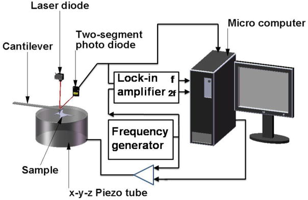
A schematic of an atomic force microscope (AFM) setup, which incorporates optical lever detection and includes electronics for investigating viscoelastic properties of samples. (Adapted from Radmacher et al.,(16) with permission of the authors and the Biophysical Society.)
Weisenhorn et al.(17) examine the local deformation of soft surfaces using AFM. Included in the samples examined are metastatic smooth muscle cells from human lungs. They generate force-versus-indentation curves for different cell orientations, with the assumption that the cell is homogenous within all areas tested. They report Young’s modulus for the cells between 0.013 and 0.15 MPa. They do report some problems with this technique, however. Deformation of the cell membrane by the tip without any applied force leads to an overestimation of the force-versus-indentation curve and subsequently an overestimation of the Young’s modulus of the cell. Scanning with too high a force on the tip also leads to cell damage. Hoh et al.(18) have employed AFM to investigate the surface morphology and mechanical properties of MDCK cells grown as monolayers. They find that the plasma membrane has an average spring constant of 2 ± 6 mN/m over a deflection range of ~35 nm (2.2 nN). From stiffness curves they report a stiffness of ~35 mN/m at 1 μm depth. Mathur et al.(19) use AFM to investigate the viscous and elastic properties of endothelial, cardiac, and skeletal muscle cells. For endothelial cells, they report a variation in elastic modulus across the cell, ranging from ~1.4 ± 0.1 kPa near the edge to ~ 6.8 ± 0.4 kPa over the nucleus. They report no variation in either skeletal or cardiac muscle with an elastic modulus of 100.3 ± 10.7 kPa across cardiac cells and 24.7 ± 3.5 kPa for skeletal muscle.
Though AFM has been used to successfully study the mechanical properties of cells, it still has a number of weaknesses. One that is inherent to the technique is the fact that many different tip shapes are used and the shape of the tip determines the nature of the force-deformation curve. This curve is used to deduce the mechanical properties, so any bias introduced by different shapes would be propagated throughout the data analysis steps and might complicate replication of experiments in different laboratories. Also, it is difficult to use commercially available AFMs with scanning electron microscopes (SEMs) to accurately visualize the structural deformation of the cell that occurs when the cell is stretched or indented by the AFM tip, since most SEMs require fixed, dessicated samples, while the AFM can be used on living cells.
Magnetic tweezers and magnetic twisting cytometry (MTC)
These techniques have been used for many studies on the physical properties of biological tissues. Some of the earliest work was by Crick and Hughes,(20) where they used magnetic particles that had been phagocytosed by chick embryo cells to examine the physical properties of the cell cytoplasm using three experimental modes of movement of the particles: twisting, dragging, and prodding. All of the methods require that beads are first exposed to magnetizing coils, which induce a transient magnetic dipole moment in the beads. A weaker, directional magnetic field or field gradient is then applied to either generate a torque to twist the beads through a specific angle (MTC), or to move the beads linearly as shown in Figure 2, (magnetic tweezers/magnetic pulling cytometry, Lele et al.(21)) In both cases, the torque or force generated is dependent on the strength of the applied magnetic field and/or its gradient as well as on bead properties.
Figure 2.

A schematic of magnetic tweezer setup used by Lele et al. to analyze single cell mechanics. (From Lele et al.(14) This article was published in Methods in Cell Biology Cell Mechanics, Wang, Y.-L. & Discher, D. E. (eds.), pp. 443–472, Academic Press, New York, © Elsevier 2007.)
Ziemann et al.(22) use this technique to measure local viscoelastic moduli of entangled actin networks. Baush et al.(23) use a modification of the Ziemann et al. setup to conduct local measurements of viscoelastic parameters of adherent cell surfaces. They are able to bring the magnetic pole piece to within 10 – 100 μm of the sample and are able to generate forces of ~10 nN.
Wang et al.(24) and Chen et al.(25) use another design to investigate cell cytoskeletal mechanics and mechanotransduction. The surface of ferromagnetic beads, normally around 0.2 μm in diameter, is coated with specific receptor ligands that promote cell attachment without cell spreading. These beads are then seeded onto the cells where they attach and subsequently a uniform magnetic field in a specific direction is applied to the beads to magnetize them. A twisting coil mounted in tandem with the magnetizing coil is used to generate a weaker magnetic field orthogonal to the initial magnetic field. This induces a twisting moment on the beads, thereby causing portions of the cell to deform. Wang’s group uses this to exert controlled shear stresses in the range from 0 to 68 Pa on cell surface receptors. They measure the angular strain as a function of the bead rotation and, for a stress of about 40 Pa, get an angular strain of about 30°.
There are some disadvantages associated with this system as well. First, it is difficult to control the region of the cell to which the beads bind. If they preferentially attach at the periphery, or near the nucleus, measurements of the mechanical properties could be biased accordingly. Next, there is no way to ensure complete binding of the beads to the cell surface, which could result in underestimation of cell stiffness. Finally, and perhaps most importantly, the beads lose magnetization with time and must be re-magnetized at specific time intervals to maintain the torque applied. Regardless, there is inherent signal degradation over time and, subsequently, experiments lasting longer than one to two hours are not generally feasible with this technique.
Micropipette aspiration
In this method, also known as elastimetry, a cell is deformed by applying gentle suction to a micropipette that is placed on the surface of the cell as shown in Figure 3a. The geometry of the resulting deformation together with the applied pressure is used to calculate the force applied. Mechanical properties of cells can then be inferred from this data. Chien et al.(26) use this technique to investigate the viscoelastic properties of erythrocyte membranes. They find that deformation occurs in two phases. The initial (rapid) phase exhibits a membrane viscosity in the range of 0.6 × 10⁻⁴ to 4 × 10⁻⁴ Pa s. The second (slower) phase shows a high membrane viscosity with a mean value of about 2 × 10⁻² Pa s. Schmid-Schonbein et al.(27) use micropipette aspiration to investigate the mechanical properties of human leukocytes. For rapid motion of the cell into the pipette, they find the shear modulus to be ~ 506 Pa and for slow motion ~130 Pa. Hiramoto (28) examines the changes in cell surface stiffness during cell cleavage (cytokinesis) in sea urchin eggs. Jones et al.(29) examine the alterations of Young’s modulus of chondrocytes from normal and osteoarthritic human cartilage. They find no appreciable difference between the Young’s modulus of normal chondrocyte cells (0.65 ± 0.63 kPa) and of the osteoarthritic chondrocyte cell (0.67 ± 0.86 kPa). A more recent study was completed by Alexopoulos et al.(30) on chondrocyte cells surrounded by a pericellular matrix for both normal and osteoarthritic cartilage. They find that for the normal cells, the Young’s modulus is the same for cells isolated from the surface (68.9 ± 18.9 kPa) as that from the middle and deep layers (62 ± 30.5 kPa). However, in osteoarthritic cartilage, the mean Young’s modulus significantly decreases from the surface zone (66.5 ± 23.3 kPa) to the middle and deep layers (41.3 ± 21.1 kPa). They conclude that the pericellular matrix has an important depth-dependent influence on the stress-strain environment of chondrocytes.
Figure 3.


Pipettes for measuring cell adhesion forces. A) A schematic showing principle of micropipette aspiration. B) – D) Sequence of images showing separation of cells using dual micropipette assay. The change in pressure in the pipetter can be used to infer the force of cell-cell adhesion. (Reproduced from The Journal of Cell Biology, 2004, 167:1183–1194. © 2004, The Rockefeller University Press.)
Chu et al.(31) use a dual micropipette assay for a slightly different application – the quantification of the strength of cadherin-dependent cell-cell adhesion (Figure 3b – 3d). Doublets of S180 cells stably transfected to express E-cadherin are allowed to adhere to each other with different times of contact. They find that separation force is strongly dependent on the time allowed for contact. A mean force of 20 nN was required to separate cells with a 30 s contact time and this increased rapidly to ~200 nN after 1 h of contact. They also report a greater separation force (350 versus 200 nN) for preexisting doublets. However, they find that preexisting doublets of S180 cells without E-cadherin have separation forces of only 50 nN.
Optical tweezers
This is a variation of magnetic tweezers where optical forces instead of magnetic forces are used to apply linear forces to cells. A laser beam is used in tandem with a dielectric bead of high refractive index to generate these optical forces. The bead surface, which is functionalized, is bound to the cell surface as in MTC. The high intensity laser beam creates a “trap,” an optical field that attracts the bead to its focus, thereby generating a force which deforms the cell (Figure 4).
Figure 4.

Schematic showing how optical tweezers are used to pull on opposite ends of a cell.
Hénon et al.(32) use this method to determine the shear modulus of the human erythrocyte membrane inferred from deformations measured as functions of the applied stress and with the assumption that the membrane is incompressible. They find that the membrane shear modulus ranges from 1.7 to 3.3 μN/m with an average value of 2.5 ± 0.4 μN/m. Dao et al.(33) also use this tool to examine the mechanics of human erythrocyte deformation, generating forces ten orders of magnitude greater than Hénon et al. Using a combination of simulation and experimental methods, they estimate the membrane shear modulus to be 13.3 μN/m. Limitations of this method include possible photo-induced damage due to the wavelength and power of the lasers, and upper limits on the amount of force that can be generated.
Micromachined force sensors and actuators
With the exception of AFM, which can use micromachined tips, the techniques we have described above use macroscopic instruments fabricated by conventional means. The semiconductor photolithography and fabrication techniques developed for the manufacture of integrated circuits have been adapted and extended to create microelectromechanical systems (MEMS), primarily out of single-crystal silicon (34). This approach has been extended to what is termed “soft lithography,” wherein polymeric materials such as silicone are used to create optically transparent and flexible microfluidic devices. (35,36). Collectively, when applied to biology, these technologies are referred to as biomicroelectromechanical systems (BioMEMS).
As an example of silicon MEMS applied to biomechanics, a recently reported technique uses a novel micromachining method, SCREAM (single-crystal reactive etching and metallization) to fabricate a force sensor for active probing and measurement of the deformation dynamics and stiffness of cells. Yang et al.(37) present a force sensor that consists of a probe attached to a backbone structure that is free to move on its axis (Figure 5a). The backbone structure is attached to flexible beams that are anchored at both ends to nonmovable bases. The chip on which the whole sensor is fabricated is driven by a piezo actuator on a movable stage with six degrees of freedom of movement. The actuator moves the probe in one direction and the resulting deflection of the attached sensor beams is recorded using optical methods. This deflection is used to estimate the force that the probe applies to the cell. The obvious advantage of this tool over others similar to it, such as the AFM and the micropipette, is the ease of calculation of the force applied to the cell based on the stiffness of the flexible beams and the deflection observed. Also, the device is set up such that it can be used to determine multidimensional (x and y) force responses of cells, unlike other methods that only probe forces in one direction. Though the device overcomes limitations of previous techniques, the production of SCREAM devices is a complicated, ten-step process involving deposition, lithography, and wet and dry etching techniques. In addition to being time-intensive, the tools and methods may either be not readily available or the fabrication process may be quite expensive.
Figure 5.

Microfabricated force sensor/actuator systems. A) Schematic of a force sensor/actuator fabricated using SCREAM technique. (Reprinted with permission of the authors from Yang et al.,(37) © 2005, American Institute of Physics.) B) Schematic of uniaxial BioMEMs device. (Reprinted from Serrell et al.,(38) with kind permission from Springer Science and Business Media.)
Serrell et al.(38) use standard surface micromachining to microfabricate a bioMEMs device for the application of strain to a cell. The principle of operation of the device is similar to a displacement-controlled uniaxial tensile machine (Figure 5b). It consists of a disk, divided in half, that serves as a platform for cell attachment. The cells attach to the disk, and because it spans the narrow gap between the two halves, the tensile properties of the mid-section of the cell can be measured. To provide actuation of the cell, one of the semicircular halves is connected to one end of a polysilicon beam, which has an annulus at the other end. A standard MEMs probe-station tip can be inserted into this annulus and used to pull one half of the platform away from the other. The polysilicon beam is supported by several folded-beam cantilever springs. The opposite half of the platform provides the force sensing for the device, using a series/parallel combination of cantilever beams to create a spring. Movement of the two platform halves is monitored with standard optics and recorded using fast cameras. Serrell’s group reports a linear force versus time curve for a single fibroblast cell attached to the platform, and also a de-adhesion force of about 1500 nN. They attribute this high value to the surface roughness of the platform, the manner in which the shear force is being applied, and the protein used to facilitate cell adhesion.
Shear flow methods
Experiments using this method consist of two basic configurations: 1) a cone-and-plate viscometer with a stationary flat plate and a rotating inverted cone which can generate laminar or turbulent flows, or 2) a parallel-plate flow chamber in which cells can be subjected to laminar flow. Figure 6a, 6b and 6c show schematics of the two basic configurations.
Figure 6.


Flow systems for measuring the effect of shear forces on cells. A) Schematic showing exploded view of the parallel plate flow chamber. B) Schematic showing cut-out view (section A- A′) of the parallel plate flow chamber. C) Schematic showing cut-out view of the cone-and-plate flow chamber. (Adapted from (81).) D) Schematic of side-view flow chamber used by Cao et al.(43) for studying cell-surface adhesion under flow conditions. (Reprinted from Cao et al.,(43) with kind permission from Springer Science and Business Media.)
The shear flow chambers can be designed to provide either a constant shear over the entire chamber or a linearly varying shear along the length/width of the chamber. The advantage of the design with linearly varying shear is that it becomes possible to apply different shear stresses between the plates along different sections of the flow chamber without having to change the flow rates or change the dimensions of the chamber. However, in both cases, the shear stress developed on the bottom of the flow chamber is dependent on many factors, including flow rate, viscosity of the fluid, channel width, and channel height. In the case of the linear varying design, two additional variables come into play. First, channel width is a function of the distance from the input port. Also, the total chamber length determines the pressure drop from the entrance to the exit port, hence affecting the amount of shear stress that can be developed. The downstream cells may also be affected by paracrine signals released by upstream cells.
Hochmuth et al.(39) use a parallel plate flow chamber with a constant shear stress at the surface to estimate the elastic shear modulus of erythrocytes adhered to a glass slide. A least-squares fit to their data gives a shear elastic modulus of 1.31 ± 0.38 Pa. Their other applications of this device involved the investigation of flow effects on cell metabolism and viability, but were not explicitly used to quantify mechanical response or characteristics.
Civelik et al.(40) examine rat aortic smooth muscle cell contractility in response to fluid shear stress and look at relationships to the Ca2+ signaling pathway. They use cell area reduction as a metric of contractility. A minimal shear stress of 11 Pa was sufficient to induce contraction. A larger shear stress of 25 Pa caused significant reduction in cell area, due to significant contraction, 3 min after the onset of flow. By 30 min of constant flow, the reduction exceeded 30%. One of their major observations is that this contractile response is Ca2+-independent. This observation was borne out by the fact that even at 25 Pa of shear stress, there was no activation of Ca2+ signaling pathways, but the cells did mount a normal response when stimulated with Ca2+-dependent agonists like potassium chloride (KCL) and thapsigarin.
Ainslie et al.(41) employ the parallel plate shear stress chamber to investigate contractile responses of vascular smooth muscle and the role of glycosaminoglycans (GAGs) on contractility and mechanotransduction. They use a step increase (0 to 25 Pa) in shear, similar to Civelik et al., as well as a ramp increase. The resultant contractility is similar in both cases. Pretreatment with heparinase III or chondroitinase ABC, which remove the GAGs heparan sulfate and chondroitin sulfate, respectively, results in a marked decrease (~20%) in cell contractility under identical shear stress.
Other labs have used this shear flow device to investigate cell properties and physiological responses, though not to investigate mechanical properties of cells. Frangos et al. (42) use a recirculation-type flow chamber to examine the effects of pulsatile, steady state, and no flow conditions on the production of prostacyclin in cultured human endothelial cells. A minimum shear stress of 10 Pa is enough to elicit a significant increase of prostacyclin. Pulsatile flow, which produces minimum and maximum shear stress of 8 and 12 Pa at a frequency of 1 Hz, results in a 2.2 fold increase in prostacylin production.
One drawback of all the above experiments involving flow chambers is that none have taken into account the inherent curvature of a cell attached to the bottom of the chamber. This means that the shear stress that is actually experienced by the cell will vary from the top of the cell to its attachment on the bottom and cannot be assumed to be the same as the shear stress on the bottom plate of the flow chamber. The shape of the cell, and hence the forces on it, will depend upon the flow rate and the velocity profile of the fluid around the cell. This is evident in the study by Cao et al.,(43) who use the setup shown in Figure 6d to study cell-surface adhesion under flow conditions. Their apparatus is optimized to obtain a side-view of the cell using mirrored side walls and they can visualize the distortion of the cell with increased flow rate. One could theoretically use the observed profile of the cell to compute the actual forces delivered to the cell by the flowing stream. An alternative method to reduce the error associated with unknown cell profile in the fluid stream would be to measure the cell thickness profile by using confocal microscopy and deducing the average shear stress experienced by the cell. However, this process would introduce additional sources of error, since confocal microscopy has a vertical resolution that is substantially less than transverse resolution.(43–45)
Stretching devices
Using these methods, cells are cultured on elastic membranes made of flexible silicone sheets whose surfaces can be modified with extracellular matrix (ECM) proteins. The stretching devices can be uniaxial, biaxial, or pressure-controlled. In some of these, the stretch can be applied in a cyclic manner at different frequencies. Wang et al.(46) subject endothelial cells to 10% cyclic uniaxial stretch on silicone membranes in the presence or absence of 2,3 butanedione monoxime (BDM), a myosin ATPase inhibitor that is used to block myosin-dependent intracellular forces. They show that 40 mM BDM prevents the formation of stress fibers and prevents cells from reorienting themselves in response to the cyclic stretch.
Zhuang et al.(47) investigate the role of pulsatile stretch on the electrical and mechanical properties of neonatal rat cardiac myocytes. Figure 7 is a schematic of their custom-fabricated stretching apparatus. Included in the device is a silicone membrane which forms part of the culture dish in which the neonatal rat myocytes were seeded and grown. They use the device to examine the effects of pulsatile stretch on some of the characteristics of the transmembrane action potential, as well as its effects on gene expression. They report an increase in N-cadherin expression with increases in the time to which the cells are subjected to pulsatile stretch, but no significant changes in cell area or nuclear size.
Figure 7.

Schematic of a custom-designed stretching device used by Zhuang et al.,(47) which includes a transparent silicone membrane and an elliptical cam whose rotation leads to cyclic stretch of the membrane. The two slide assemblies oscillate horizontally on stainless cylindrical rods (red arrows) and support the transparent silicone membrane, which provides the restoring force to maintain the slides in contact with the cam. The silicone cell reservoir is a segment of silicone tubing glued to the silicone membrane to form the walls of the culture dish. Two clamps produce slight tension along the central axis of the stretch apparatus and thereby reduce transverse shrinking.
The methods discussed above all involve the application of active forces either to single cells or a population of cells in culture. One of the main drawbacks with the use of these stretching devices is wrinkling patterns that develop on the sheets and which tend to distort the actual forces that are applied to the sheets. Zhuang et al. try to minimize this effect by using clamps on either side of the membrane. Also, as the sheets are continuous, all deformations and displacements are propagated across the entire surface, making calculation of discrete forces and cellular attachment properties very computationally intensive.
One point possibly worthy of future investigation is the growth of cells on substrates whose stiffness is more closely matched to that encountered by the cell in vivo, rather than on ones that are so stiff that the cell-generated reaction forces will be vastly smaller than the forces used to stretch the macroscopic, underlying silicone substrate. In a situation with better mechanical matching, it might be possible to observe how a cell remodels itself or proliferates in a manner to reduce or redistribute the externally applied forces. In a stiff system, the cells can remodel, but the external forces may always dominate.
Carbon fiber (CF)-based systems
This method involves the use of carbon fibers, which are normally mounted in glass capillaries and attached to precise position-control devices with feedback control mechanisms. The carbon fibers are attached to cells and used as a means to both apply active forces and record forces generated by the cell. The image of the carbon fibers is projected through optics onto a photodiode array which converts this into a usable signal for the feedback control system. The optical system is also connected to an image recording system and can be used to capture and record changes in length of the cell (Figure 8a). Though this technique could potentially be used for many cell types, it has recently been used to study single cardiac myocytes, which are orders of magnitude shorter than skeletal muscle fibers and correspondingly harder to study. Yasuda et al.(48) use this setup to investigate the mechanics of single rat cardiac myocytes under isometric and physiologically loaded conditions. They also investigate the effects of inotropic intervention on myocyte force generation. They report problems with carbon fiber compliance and indicate that it is quite difficult to produce virtually isometric conditions. They plot force-length relationships and extract workload data. Work output has a maximum value at an intermediate auxotonic load, and falls off above and below this optimal value. Nishimura et al.(49) make modifications and improvements to the feedback control system used by Yasuda et al. and use it to also investigate rat cardiac myocyte mechanics under isometric, unloaded, and physiologically loaded conditions. Some of the limitations they report include damage to the cells during attachment of the fibers, inaccuracy in measuring sarcomere length due to focus issues, and possible bias introduced into the data by avoiding cells that were too irritable to obtain stable recordings. Iribe et al.(50) make further modifications to this setup by introducing the use of bidirectional control instead of the single-sided control used by Yasuda et al.(33) and Nishimura et al.,(34) which reduced sarcomere blurring (Figure 8b). They investigate the effects of independently varying preload and after load, as well as modes of contraction on the force-length relationships of guinea pig ventricular cardiomyocytes. Some of their reported findings include the fact that the end systolic force-length relation is virtually independent of load at sarcomere lengths of 1.85 to 2.05 μm. It is important to recognize that this approach provides true, closed-loop mechanical control of a single cell, in which the compliance of the measurement system can be controlled independently of its displacement, thereby allowing exploration of cellular mechanics over the full range of forces, displacements, and velocities that are required to fully specify the parameters for an active, viscoelastic model of cellular mechanics.
Figure 8.


Active control of pairs of carbon fibers for studies of cardiomyocyte mechanics. A) Schematic showing the general principle of operation of the carbon fiber system used by Yasuda et al.(48) (Adapted from Yasuda et al.(48)) B) Experimental setup and images of carbon fibers attached to individual cardiac myocytes (From Iribe et al.(50) Used with permission of the American Journal of Physiology-Heart and Circulatory Physiology.)
Passive Methods
Detection of the mechanical forces that single cells exert generally involves the use of various flexible substrates which are nontoxic and either transparent or reflective to a high degree, such that deflections can be measured using light microscopy or a variation of it. We use the term “passive methods” to describe the techniques outlined below with some caution. Due to the inherent nature of some of the materials used, very soft materials may detect the mechanical forces exerted by the cells isotonically, i.e., without exerting any forces, whereas others being very stiff will detect these forces isometrically with any changes in length of the systems. Some of the techniques are midway between these two extremes.
Elastic substratum method
The first successful attempt to measure traction forces of individual cells using artificial flexible substrata was developed by Harris et al.(51) The cells were cultured on substrates made of flexible silicone sheets (Figure 9a). These sheets were made by polymerizing silicone fluid using a flame. The stiffness of the sheets could be varied by altering crosslinking time and initial viscosity of the silicone fluid. The sheets were coated with extracellular matrix (ECM) proteins to promote cell adhesion and attachment. As the cells exert forces on the sheets, they cause wrinkling patterns which can be visualized under a light microscope. The patterns are compared to those generated by a pulled micropipette which has been calibrated for force. Danowski (52) uses this system to investigate the effects of microtubule inhibitors on fibroblast contractility and actin reorganization. Colcemid, nocodazole and vinblastine are found to increase the contractile state of fibroblasts on the silicone sheets. This is determined by an increase in the size and number of wrinkles in the rubber sheet. The main drawback of this method is that there is not a simple way of converting the wrinkle patterns formed into a traction force map. Inaccuracy in comparing patterns, and hence measures of force, introduces significant error.
Figure 9.
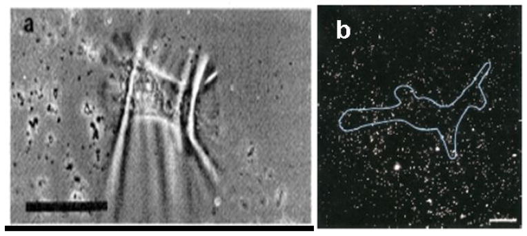
Polymer films for cell traction force microscopy. A) Wrinkling patterns produced by chicken heart fibroblasts on silicone rubber sheets. The bar is 50 μm. (From Harris et al.(51) Reprinted with permission from AAAS.) B) Fluorescent image of a human airway smooth muscle (HASM) cell cultured on a flexible polyacrylamide gel with embedded fluorescent beads. 20 μm bar. (From Butler et al.(57) Used with permission of the American Journal of Physiology-Cell Physiology.)
Flexible sheets with embedded beads
A variant of the above method involves embedding either normal latex beads or fluorescently tagged beads in the elastic substratum (Figure 9b). The positions of the beads are tracked and the displacements over time are recorded. Cellular forces are inferred from the measured displacements. Lee et al.(53) use this device to estimate the traction forces exerted by fish keratocytes. They produce vector diagrams by calculating the displaced and undisplaced bead positions with respect to the centroid of a moving cell. They report traction forces ranging from a minimum of 7.5 nN to a maximum of about 20 nN. Pelham and Wang (54) also use raw displacement data as a qualitative map of the local traction, citing the difficulty and computational intensity of deconvolving the displacements to estimate the traction forces. The primary flaw in both of these methods is that neither group was able to account for the interdependence of bead displacement data due to the propagation of deformations throughout the entire sheet surface. This flaw has been addressed by other groups. Dembo et al.(55) address this issue using statistical methods. They estimate traction forces by considering the problem as a superposition of elementary “delta influences.” They then use maximum likelihood statistical methods to find the most probable amplitude and locations of the traction forces. Using this method they report that a typical locomoting keratocyte generates a maximum traction force of ~ 140 nN.
Munevar et al.(56) use methods similar to those of Dembo et al.(55) to study traction forces generated by normal and H-ras transformed (PAP2) 3T3 fibroblasts to determine the impact of oncogenic transformation on traction forces. They make some modifications to the system to improve spatial resolution and calculation of results. They report significant differences in the spatial distribution of traction forces between the PAP2 cells and the normal ones, with the latter exhibiting a more scattered unstable distribution. The mean traction forces are also significantly different, with the PAP2 cells showing an order of ten reduction in the magnitude of the forces generated. Butler et al.(57) use Fourier transform traction cytometry (FTTC) to compute the traction field produced by human airway smooth muscle cells in a bead-embedded flexible substrate. Using this technique, they report a maximum traction magnitude of about 400 Pa. Though such approaches address the critical flaw in the flexible-sheet technique, they do introduce a few disadvantages. Deconvolution of forces from displacement field maps is both a difficult and computationally intensive process. It is also very difficult to obtain precise measurements of discrete forces generated by different parts of a cell.
Flexible sheets with micropatterned dots or grids
An improvement to the Lee et al.(37) and Butler et al.(57) techniques involves imprinting dots on the flexible sheet and observing the deformation of the grid from the ideal grid. Models of deformation can then be applied to the grid and the cellular forces inferred from the deformations produced. Balaban et al.(58) use this tool to measure the traction forces exerted by rat cardiac myocytes and endothelial cells. They compute the forces generated at the focal adhesions using elastic theory based on the semi-infinite space. Unfortunately, they have to make the same assumption as in the case for the embedded beads. They assume that the forces originate from the measured locations and do not propagate across the substrate. They solve the inverse problem of computing the tractions given the displacements using least square minimization techniques. Using this method they report maximum traction forces of ~20 nN for rat cardiac fibroblast cells and ~70 nN for rat cardiac myocytes.
Micromachined cantilever beam
This technique uses traditional micromachining techniques. A horizontal cantilever beam with an attachment pad at the end and a well beneath is used to measure cell traction forces (Figure 10). Chicken fibroblast cells are seeded on the substrates. Cells are observed crawling over the cantilevers, which have been calibrated for force using pulled glass micropipettes. A measure of cell traction force is obtained from a product of the cantilever deflection and the stiffness obtained from calibration. Galbraith et al.(59) use this micromachined device to estimate the traction forces of chicken embryo fibroblast cells. They report forces as high as 100 nN for the tail region of the fibroblast. This device does not have the problem in which strain propagates across the surface and therefore does not require sophisticated computational algorithms to calculate the cellular forces; however, there are some disadvantages. The cantilever beam can only move in one direction, hence forces generated in directions other than the free axis cannot be measured. Also, there is a spatial resolution limitation, and the fabrication technique is quite challenging.
Figure 10.
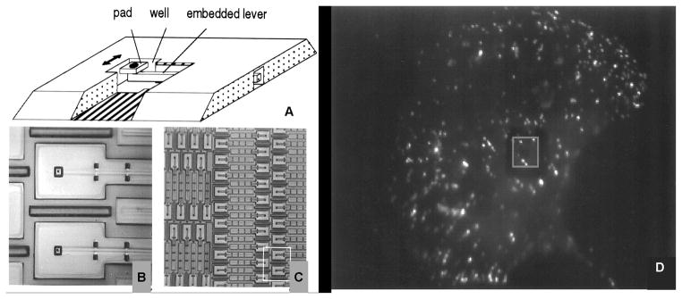
Cantilever beam device and fluorescent image of chicken embryo fibroblasts (CEFs) cell plated on the micromachined substrate. (Adapted from Galbraith et al.,(59) PNAS 94, 9114–9118, © 1997 National Academy of Sciences, U.S.A.)
Array of vertical microcantilevers
This technique overcomes the limitations of the horizontal cantilever system by Galbraith et al. An array of vertical microcantilevers that have two degrees of freedom is used instead of a single horizontal microcantilever. The individual microcantilevers in the array are usually made of an elastomeric material such as polydimethlysiloxane (PDMS). Tan et al.(60) are the first group to report the use of these arrays to investigate cell traction forces (Figure 11a – 11b). They use soft lithography techniques to make the microcantilevers of PDMS. The arrays in their device have microcantilevers that are 3 μm in diameter and 11 μm tall and have a center-to-center separation of 9 μm. They use this device in combination with micropatterning techniques to investigate the traction forces exerted by spread and unspread bovine pulmonary artery smooth muscle cells (BPASMCs), and show that spread cells exert much greater forces on the microcantilevers than unspread cells. For the spread cells, a maximum force of about 90 nN is recorded.
Figure 11.

Vertical microcantilevers. A) – B) Scanning electron micrograph (SEM) images of representative smooth muscle cells attached to array of vertical microcantilevers (From Tan et al.,(60) PNAS 100, 1484–1489,© 2003 National Academy of Sciences, U.S.A.) C) Scanning electron micrograph of closely spaced array of vertical microcantilevers produced using reactive ion etching techniques, and D) Individual MDCK cells attached to the array (From du Roure et al.,(62) PNAS 102, 2390–2395 © 2005 National Academy of Sciences, U.S.A.)
A variation of this technique has been developed by du Roure et al.(Figure 11c– 11d).(61,62) They employ photolithographic methods in combination with Deep Reactive Ion Beam Etching (DRIE) to produce master molds in silicon that have much better spatial resolutions and smaller sizes than those produced by Tan et al. They also use PDMS as the flexible cantilever material. The improvement in scale and resolution is impressive, but this is a considerably more expensive process than that used by Tan et al. Endothelial cells are cultured on the device and allowed to grow to confluence, forming monolayers. They report a maximum traction force of 40 nN exerted by the monolayer at its edge. Individual cells observed on the device generate maximum forces of about 4 nN. Both devices provide a powerful tool, which is used to study microforces of expanding monolayers and single cells as well as investigate the relationship between cell shape, focal adhesion area, and traction forces generated.
Petronis et al.(63) have also developed cantilever arrays for investigation of mechanical cell-substrate interactions. They fabricate their force-sensitive arrays directly from silicon – a major difference from the two previous methods. They also include attachment pads on their arrays. They employ intermediate lithography steps (masking techniques) to pattern areas with different cantilever heights, thereby generating areas with inherently different mechanical properties. Using a modified design with microcantilevers having a stiffness of 116 nN/μm embedded between rigid ridges, they measure the traction forces exerted by primary human saphenous vein endothelial cells (HSVEC). A range of forces between 7 nN and 40 nN is reported. The main drawback with their technique is that it is not suited to rapid mass-production of the devices through replica casting. Since the arrays and ridges are formed directly in the silicon wafer, any damage to it would require reproduction of the entire device.
Our laboratory has focused on using techniques developed by Tan et al. and du Roure et al. to investigate cellular biomechanics and microforces in vitro. We have been able to produce devices similar to that produced by Tan et al. Due to limitations of the contact lithography step for making the original master molds, we were unable to make molds with microcantilever diameters less than 3 μm and spacing less than 8 μm. We improved the lithography technique using contrast enhancement methods and have been able to make microcantilevers with diameters of 2 μm, 7 μm tall, and with spacing of 5 μm, which is close to the theoretical limits for the process.(64) This reduction in feature size is not as impressive as the molds produced using the technique reported by du Roure et al. However, unless process parameters are carefully optimized, it appears that DRIE can produce scalloping on the side walls of the silicon master mold, making separation of the PDMS mold very difficult, if not impossible. Based upon our experience, a cryogenic DRIE process may be better suited for fabrication of these devices.1
Also of concern to us was the difficulty in tracking accurately the displacements of the individual microcantilevers in real time during experiments. The technique of microcontact printing fluorescent proteins that had been reported by Tan et al. worked only to a certain degree due to rapid photobleaching and cell interaction with the proteins. We have introduced a technique that improves this by using fluorescent quantum dots instead, which has allowed us to obtain cell force data for both live cells and fixed cells,(64) as shown in Figure 12. It has yet to be determined whether these quantum-dot labels can survive the processing steps of immunohistochemistry, or whether the cells adhere differently to the ends of the labeled microcantilevers. There are still some issues related to the vertical cantilever method that we have yet to address. Neither our study nor those before it address the possibility that the differences between the indices of refraction of the cell, the microcantilevers, and the fluid media will produce refractive artifacts that distort the image and the apparent position of a microcantilever relative to cellular structures. With inverted microscopy, the cells are imaged through the PDMS posts, which when bent might act as tilted cylindrical lenses. With upright microscopy, the posts are viewed through the cell, which may have a curved surface that could act as either a convex or concave lens that might shift the apparent position or size of objects beneath it.
Figure 12.
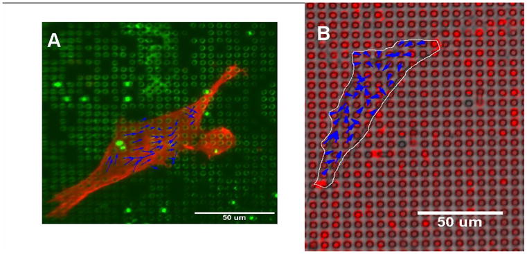
Quantum dot technique for labeling microcantilevers. A) Human airway smooth muscle cell fixed and stained for actin on microcantilever array labeled with green dots. B) Live human airway smooth muscle cell on microcantilever array labeled with red dots. Blue arrows are representative cell force vectors. (Reprinted from Addae-Mensah et al.,(64) © 2007, with permission from Elsevier.)
It must be noted that other techniques have been used to produce arrays of vertical microcantilevers though not all have been for applications in cellular biomechanics in vitro. McKnight et al.(65,66) have developed a technique where they grow carbon nanofibers, which they use for applications such as DNA delivery to cells as well as for biochemical manipulation. These vertical nanofiber arrays could potentially be used to study cellular biomechnics and have the added advantage that they can be used for biochemical manipulation through functionalization of the surfaces.(67) Kim et al.(68) also use silicon nanowires as an interface for mammalian cells, though their application has no direct relation to cellular biomechanics.
Combination of Active and Passive Methods
The active methods described above normally provide indication of the cell stiffness or elastic/viscoelastic properties, whereas passive methods are used to investigate cell traction forces or tensile stress. The two methods can be combined to investigate the relationship between cell stiffness under certain conditions and the corresponding tensile or prestress. Wang et al.(69) attempt to do this using a combination of oscillatory MTC for cell stiffness measurements and flexible polyacrylamide gel substrates with fluorescent beads for measurement of traction forces. Using this method they conclude that there is a strong association between the cell stiffness exhibited by a cell and the level of tensile stress within the cytoskeleton. We believe that pursuing a combination of active and passive methods could provide more insight on cell biomechanics and mechanobiology. Towards this goal we have introduced a technique to attach structures made from a photocurable epoxy, such as SU-8, to our microcantilevers.(70) We hope to use this as a platform to agitate the underlying substrate (microcantilever arrays) as well as a means to apply active forces to cells attached to them. Figure 13 shows a scanning electron micrograph (SEM) image of a 60 μm disc and a differential interference contrast (DIC) image of a human airway smooth muscle cell attached to one of these composite structures.2
Figure 13.
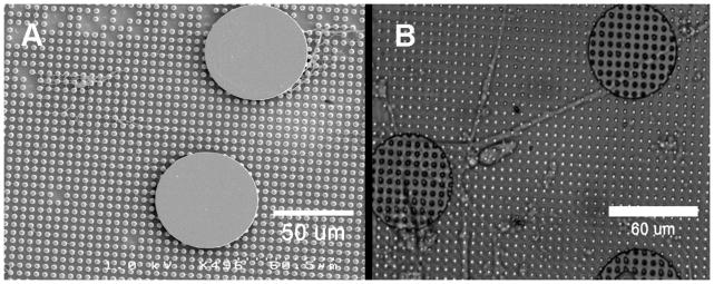
Structures on microcantilevers. A) Scanning electron micrograph (SEM) of a 60 μm disc attached to the microcantilever array. B) Differential interference contrast (DIC) image of human airway smooth muscle cell attached to two such discs.
Sniadecki et al.(71) have used a different approach in pursuit of this goal. They incorporate magnetic cobalt (Co) nanowires into similar microcantilevers made by Tan et al.(60) A uniform magnetic field is then applied to the array and any microcantilevers which have nanowires incorporated within are displaced a specified distance. The nonmagnetic microcantilevers together with the magnetic ones are then used to monitor for the changes in forces. They use this system to investigate focal adhesion and traction force response to the active forces applied to the cells via the magnetic microcantilevers. Included in some of their findings is a significant difference in average focal adhesion area at actuated magnetic microcantilevers versus nonactuated, with the former being larger. They find that multiple stimulations also produce larger focal adhesion areas than single actuations.
Summary
The importance of studying cellular biomechanics and mechanobiology cannot be overemphasized. It has been shown that there are linkages between the structure, mechanical properties, and the phenotype behavior and function of cells in their microenvironments. These linkages may be important in many physiological and pathophysiological conditions, and a better understanding of these processes could have implications not only in human health but in the biotechnology industry as well. Many methods and techniques have been developed and used to investigate the mechanical properties and microforce generation for cells in vitro and most of these are able to generate or detect forces in the pN to nN range. We have classified these methods based on two general categories – active and passive – and looked at some of their advantages and disadvantages. We also looked briefly at modifications that we have implemented in our lab in an attempt to improve some of these techniques and methods. It must be noted that this minireview does not cover the important area of micro- and nanomechanical sensors used for environmental, chemical, and biological analyte detection, which has been covered elsewhere.(72)
The novelty in this field is remarkable and has provided many opportunities to investigate cell biomechanics. Although there are still some limitations that need to be overcome, the field is rapidly evolving to address some of these issues. A significant challenge for the future will be to extend some of these techniques and methods to measurement of subcellular phenomena. There are several reasons for this. For example, the cell cytoskeleton has been shown to both support mechanical loads applied to the cell as well as generate some of the forces exerted by the cells. It will therefore be necessary to decouple these two to get any measure of quantitative data for cell cytoskeletal mechanics and force generation. One promising approach has been the use of subcellular laser ablation (SLA) in conjunction with fluorescence recovery after photobleaching (FRAP) to surgically cut portions of the cell cytoskeleton and simultaneously monitor responses.(73) Changes in cell traction forces are determined using the microbeads in the flexible sheets method outlined previously. The combination of active and passive methods may be an alternative route to take in this case. Laser ablation can also be used to determine cell-cell forces in the developing embryo.(74,75)
Another challenge deals with the resolution and sensitivities that will be required at this scale. Current techniques are able to detect and produce forces in the piconewton to nanonewton range. If higher resolutions or sensitivities are required, such as in the femtonewton range which may be the case for subcellular recordings, then issues such as thermal effects come into play. Some of the current techniques may not be adequate in this case. The most promising is that of optical tweezers, which have been used to detect and produce forces in the range of a few piconewtons in the study of myosin molecule mechanics (76) and single strand (ssDNA) and double strand (dsDNA) DNA molecules.(77,78) Most of these measurements have been obtained in purified systems where the subcellular components are removed from the cellular environment before measurements are made. Though providing greater insight into cell structure, function, and biomechanics, they do not include temporal and spatial dynamics on the cellular scale, which are equally important and essential for understanding.
One outstanding question is the extent to which all of these techniques and measurement systems inherently affect the behavior and response of the cell; i.e., if the cell behaves in a particular way because of the specific tool and method being used, then is the measured response a true indication of what was intended to be measured or is it a combination of that and other effects, such as remodeling and reorganization? For example, to what extent does the stiffness of the microcantilever array or the elastomer sheet have on the physiological response of the cells? These devices are not ideally stiff force transducers, but exhibit physical distortions whose amplitudes can approach the dimensions of a cell. It is clear that the stiffness of the substrate can affect cellular phenotype.(79,80) Further studies in the field are needed to find answers to these questions.
In summary, we have reviewed the breadth of modern techniques that are being developed to quantify and manipulate cellular forces. The application of these or similar techniques to biology may allow questions to be answered that have heretofore proved resistant to quantitative analysis. More importantly, the development of new measurement modalities may provide answers to questions that might not have been previously asked, in that there were no means to provide the answers. It is important that those who can bring new force-measurement technologies to biology work closely with the scientists seeking to understand biological forces, so that the measurement techniques and the questions they answer can evolve in consort.
Acknowledgments
We thank Allison Price for extensive editing of the manuscript. We also acknowledge the support of the Vanderbilt Institute for Integrative Biosystems Research and Education (VIIBRE), the Whitaker Foundation, the NIH (R01 HLO68144) and the Simons Center for Systems Biology at the Institute for Advanced Study.
Footnotes
Addae-Mensah, KA”A microfabricated microcantilever array - A platform for investigation of cellular biomechanics and microforces in-vitro” (PhD Dissertation, Vanderbilt University, In Preparation).
Addae-Mensah, KA “A microfabricated microcantilever array - A platform for investigation of cellular biomechanics and microforces in-vitro” (PhD Dissertation, Vanderbilt University, In Preparation).
Reference List
- 1.Stopak D, Wessells NK, Harris AK. Morphogenetic Rearrangement of Injected Collagen in Developing Chicken Limb Buds. Proc Natl Acad Sci. 1985;82:2804–2808. doi: 10.1073/pnas.82.9.2804. [DOI] [PMC free article] [PubMed] [Google Scholar]
- 2.Discher DE, Janmey P, Wang YL. Tissue cells feel and respond to the stiffness of their substrate. Science. 2005;310:1139–1143. doi: 10.1126/science.1116995. [DOI] [PubMed] [Google Scholar]
- 3.Kung C. A possible unifying principle for mechanosensation. Nature. 2005;436:647–654. doi: 10.1038/nature03896. [DOI] [PubMed] [Google Scholar]
- 4.Ingber DE. Cellular mechanotransduction: putting all the pieces together again. FASEB J. 2006;20:811–827. doi: 10.1096/fj.05-5424rev. [DOI] [PubMed] [Google Scholar]
- 5.Ali MH, Schumacker PT. Endothelial responses to mechanical stress: Where is the mechanosensor? Critical Care Medicine. 2002;30:S198–S206. doi: 10.1097/00003246-200205001-00005. [DOI] [PubMed] [Google Scholar]
- 6.Lehoux S, Tedgui A. Cellular mechanics and gene expression in blood vessels. Journal of Biomechanics. 2003;36:631–643. doi: 10.1016/s0021-9290(02)00441-4. [DOI] [PubMed] [Google Scholar]
- 7.Grodzinsky AJ, Levenston ME, Jin M, Frank EH. Cartilage tissue remodeling in response to mechanical forces. Annual Review of Biomedical Engineering. 2000;2:691. doi: 10.1146/annurev.bioeng.2.1.691. [DOI] [PubMed] [Google Scholar]
- 8.Herberhold C, Faber S, Stammberger T, Steinlechner M, Putz R, Englmeier KH, Reiser M, Eckstein F. In situ measurement of articular cartilage deformation in intact femoropatellar joints under static loading. Journal of Biomechanics. 1999;32:1287–1295. doi: 10.1016/s0021-9290(99)00130-x. [DOI] [PubMed] [Google Scholar]
- 9.van Netten SM, Kros CJ. Gating energies and forces of the mammalian hair cell transducer channel and related hair bundle mechanics. Proceedings of the Royal Society of London Series B-Biological Sciences. 2000;267:1915–1923. doi: 10.1098/rspb.2000.1230. [DOI] [PMC free article] [PubMed] [Google Scholar]
- 10.Liao ZJ, Feng S, Popel AS, Brownell WE, Spector AA. Outer hair cell active force generation in the cochlear environment. Journal of the Acoustical Society of America. 2007;122:2215–2225. doi: 10.1121/1.2776154. [DOI] [PubMed] [Google Scholar]
- 11.Maffulli N, Wong J. Rupture of the Achilles and patellar tendons. Clinics in Sports Medicine. 2003;22:761–776. doi: 10.1016/s0278-5919(03)00009-7. [DOI] [PubMed] [Google Scholar]
- 12.Yin SH, Zhang XQ, Zhan C, Wu JT, Xu JC, Cheung J. Measuring single cardiac myocyte contractile force via moving a magnetic bead. Biophys J. 2005;88:1489–1495. doi: 10.1529/biophysj.104.048157. [DOI] [PMC free article] [PubMed] [Google Scholar]
- 13.Smith DH, Wolf JA, Meaney DF. A New Strategy to Produce Sustained Growth of Central Nervous System Axons: Continuous Mechanical Tension. Tissue Engineering. 2001;7:131–139. doi: 10.1089/107632701300062714. [DOI] [PubMed] [Google Scholar]
- 14.Shore SA, Moore PE. Regulation of [beta]-adrenergic responses in airway smooth muscle. Respiratory Physiology & Neurobiology. 2003;137:179–195. doi: 10.1016/s1569-9048(03)00146-0. [DOI] [PubMed] [Google Scholar]
- 15.Radmacher M, Fritz M, Kacher CM, Cleveland JP, Hansma PK. Measuring the viscoelastic properties of human platelets with the atomic force microscope. Biophys J. 1996;70:556–567. doi: 10.1016/S0006-3495(96)79602-9. [DOI] [PMC free article] [PubMed] [Google Scholar]
- 16.Radmacher M, Tillmann RW, Gaub HE. Imaging viscoelasticity by force modulation with the atomic force microscope. Biophys J. 1993;64:735–742. doi: 10.1016/S0006-3495(93)81433-4. [DOI] [PMC free article] [PubMed] [Google Scholar]
- 17.Weisenhorn AL, Khorsandi M, Kasas S, Gotzos V, Butt HJ. Deformation and height anomaly of soft surfaces studied with an AFM. Nanotechnology. 1993;4:106–113. [Google Scholar]
- 18.Hoh JH, Schoenenberger CA. Surface morphology and mechanical properties of MDCK monolayers by atomic force microscopy. J Cell Sci. 1994;107:1105–1114. doi: 10.1242/jcs.107.5.1105. [DOI] [PubMed] [Google Scholar]
- 19.Mathur AB, Collinsworth AM, Reichert WM, Kraus WE, Truskey GA. Endothelial, cardiac muscle and skeletal muscle exhibit different viscous and elastic properties as determined by atomic force microscopy. Journal of Biomechanics. 2001;34:1545–1553. doi: 10.1016/s0021-9290(01)00149-x. [DOI] [PubMed] [Google Scholar]
- 20.Crick FHC, Hughes AFW. The physical properties of cytoplasm: A study by means of the magnetic particle method Part I. Experimental Experimental Cell Research. 1950;1:37–80. [Google Scholar]
- 21.Lele TP, Sero JE, Matthews BD, Kumar S, Xia S, Polte T, Overby D, Wang N, Ingber DE. In: Methods in Cell Biology Cell Mechanics. Wang Y-L, Discher DE, editors. Academic Press; New York: 2007. pp. 443–472. [DOI] [PubMed] [Google Scholar]
- 22.Ziemann F, Radler J, Sackmann E. Local measurements of viscoelastic moduli of entangled actin networks using an oscillating magnetic bead micro-rheometer. Biophys J. 1994;66:2210–2216. doi: 10.1016/S0006-3495(94)81017-3. [DOI] [PMC free article] [PubMed] [Google Scholar]
- 23.Bausch AR, Moller W, Sackmann E. Measurement of Local Viscoelasticity and Forces in Living Cells by Magnetic Tweezers. Biophys J. 1999;76:573–579. doi: 10.1016/S0006-3495(99)77225-5. [DOI] [PMC free article] [PubMed] [Google Scholar]
- 24.Wang N, Butler JP, Ingber DE. Mechanotransduction Across the Cell-Surface and Through the Cytoskeleton. Science. 1993;260:1124–1127. doi: 10.1126/science.7684161. [DOI] [PubMed] [Google Scholar]
- 25.Chen J, Fabry B, Schiffrin EL, Wang N. Twisting integrin receptors increases endothelin-1 gene expression in endothelial cells. Am J Physiol Cell Physiol. 2001;280:C1475–C1484. doi: 10.1152/ajpcell.2001.280.6.C1475. [DOI] [PubMed] [Google Scholar]
- 26.Chien S, Sung KL, Skalak R, Usami S, Tozeren A. Theoretical and experimental studies on viscoelastic properties of erythrocyte membrane. Biophys J. 1978;24:463–487. doi: 10.1016/S0006-3495(78)85395-8. [DOI] [PMC free article] [PubMed] [Google Scholar]
- 27.Schmid-Schonbein GW, Sung KL, Tozeren H, Skalak R, Chien S. Passive mechanical properties of human leukocytes. Biophys J. 1981;36:243–256. doi: 10.1016/S0006-3495(81)84726-1. [DOI] [PMC free article] [PubMed] [Google Scholar]
- 28.Hiramoto Y. In: Methods in Cell Biology Echinoderm Gametes and Embryos. Schroeder TE, editor. Academic Press, Inc; New York: 1986. pp. 435–442. [Google Scholar]
- 29.Jones WR, Ping Ting-Beall H, Lee GM, Kelley SS, Hochmuth RM, Guilak F. Alterations in the Young’s modulus and volumetric properties of chondrocytes isolated from normal and osteoarthritic human cartilage. Journal of Biomechanics. 1999;32:119–127. doi: 10.1016/s0021-9290(98)00166-3. [DOI] [PubMed] [Google Scholar]
- 30.Alexopoulos LG, Haider MA, Vail TP, Guilak F. Alterations in the Mechanical Properties of the Human Chondrocyte Pericellular Matrix With Osteoarthritis. Journal of Biomechanical Engineering. 2003;125:323–333. doi: 10.1115/1.1579047. [DOI] [PubMed] [Google Scholar]
- 31.Chu YS, Thomas WA, Eder O, Pincet F, Perez E, Thiery JP, Dufour S. Force measurements in E-cadherin-mediated cell doublets reveal rapid adhesion strengthened by actin cytoskeleton remodeling through Rac and Cdc42. The Journal of Cell Biology. 2004;167:1183–1194. doi: 10.1083/jcb.200403043. [DOI] [PMC free article] [PubMed] [Google Scholar]
- 32.Henon S, Lenormand G, Richert A, Gallet F. A New Determination of the Shear Modulus of the Human Erythrocyte Membrane Using Optical Tweezers. Biophys J. 1999;76:1145–1151. doi: 10.1016/S0006-3495(99)77279-6. [DOI] [PMC free article] [PubMed] [Google Scholar]
- 33.Dao M, Lim CT, Suresh S. Mechanics of the human red blood cell deformed by optical tweezers [Journal of the Mechanics and Physics of Solids, 51 (2003) 2259–2280] Journal of the Mechanics and Physics of Solids. 2005;53:493–494. [Google Scholar]
- 34.Grayson ACR, Shawgo RS, Johnson AM, Flynn NT, Yawen LI, Cima MJ, Langer R. A BioMEMS review: MEMS technology for physiologically integrated devices. Proceedings of the IEEE. 2004;92:6–21. [Google Scholar]
- 35.Xia Y, Whitesides GM. Soft Lithography. Annual Review of Materials Science. 1998;28:153–184. [Google Scholar]
- 36.McDonald JC, Duffy DC, Anderson JR, Chiu DT, Wu HK, Schueller OJA, Whitesides GM. Fabrication of microfluidic systems in poly(dimethylsiloxane) Electrophoresis. 2000;21:27–40. doi: 10.1002/(SICI)1522-2683(20000101)21:1<27::AID-ELPS27>3.0.CO;2-C. [DOI] [PubMed] [Google Scholar]
- 37.Yang S, Saif T. Micromachined force sensors for the study of cell mechanics. Review of Scientific Instruments. 2005;76:044301–044308. [Google Scholar]
- 38.Serrell DB, Oreskovic TL, Slifka AJ, Mahajan RL, Finch DS. A uniaxial bioMEMS device for quantitative force-displacement measurements. Biomedical Microdevices. 2007;9:267–275. doi: 10.1007/s10544-006-9032-4. [DOI] [PubMed] [Google Scholar]
- 39.Hochmuth RM, Mohandas N, Blackshear PL. Measurement of the elastic Modulus for red cell membrane using a fluid mechanical technique. Biophys J. 1973;13:747–762. doi: 10.1016/S0006-3495(73)86021-7. [DOI] [PMC free article] [PubMed] [Google Scholar]
- 40.Civelek M, Ainslie K, Garanich JS, Tarbell JM. Smooth muscle cells contract in response to fluid flow via a Ca2+-independent signaling mechanism. J Appl Physiol. 2002;93:1907–1917. doi: 10.1152/japplphysiol.00988.2001. [DOI] [PubMed] [Google Scholar]
- 41.Ainslie KM, Garanich JS, Dull RO, Tarbell JM. Vascular smooth muscle cell glycocalyx influences shear stress-mediated contractile response. J Appl Physiol. 2005;98:242–249. doi: 10.1152/japplphysiol.01006.2003. [DOI] [PubMed] [Google Scholar]
- 42.Frangos JA, Eskin SG, McIntire LV, Ives CL. Flow effects on prostacyclin production by cultured human endothelial cells. Science. 1985;227:1477–1479. doi: 10.1126/science.3883488. [DOI] [PubMed] [Google Scholar]
- 43.Cao J, Usami S, Dong C. Development of a side-view chamber for studying cell-surface adhesion under flow conditions. Annals of Biomedical Engineering. 1997;25:573–580. doi: 10.1007/BF02684196. [DOI] [PubMed] [Google Scholar]
- 44.Dong C, Cao J, Struble EJ, Lipowsky HW. Mechanics of leukocyte deformation and adhesion to endothelium in shear flow. Annals of Biomedical Engineering. 1999;27:298–312. doi: 10.1114/1.143. [DOI] [PubMed] [Google Scholar]
- 45.Leyton-Mange J, Yang S, Hoskins MH, Kunz RF, Zahn JD, Dong C. Design of a side-view particle imaging velocimetry flow system for cell-substrate adhesion studies. Journal of Biomechanical Engineering-Transactions of the Asme. 2006;128:271–278. doi: 10.1115/1.2165689. [DOI] [PMC free article] [PubMed] [Google Scholar]
- 46.Wang JHC, Goldschmidt-Clermont P, Yin FCP. Contractility Affects Stress Fiber Remodeling and Reorientation of Endothelial Cells Subjected to Cyclic Mechanical Stretching. Annals of Biomedical Engineering. 2000;28:1165–1171. doi: 10.1114/1.1317528. [DOI] [PubMed] [Google Scholar]
- 47.Zhuang JP, Yamada KA, Saffitz JE, Kleber AG. Pulsatile stretch remodels cell-to-cell communication in cultured myocytes. Circ Res. 2000;87:316–322. doi: 10.1161/01.res.87.4.316. [DOI] [PubMed] [Google Scholar]
- 48.Yasuda Si, Sugiura S, Kobayakawa N, Fujita H, Yamashita H, Katoh K, Saeki Y, Kaneko H, Suda Y, Nagai R, Sugi H. A novel method to study contraction characteristics of a single cardiac myocyte using carbon fibers. Am J Physiol Heart Circ Physiol. 2001;281:H1442–H1446. doi: 10.1152/ajpheart.2001.281.3.H1442. [DOI] [PubMed] [Google Scholar]
- 49.Nishimura S, Yasuda Si, Katoh M, Yamada KP, Yamashita H, Saeki Y, Sunagawa K, Nagai R, Hisada T, Sugiura S. Single cell mechanics of rat cardiomyocytes under isometric, unloaded, and physiologically loaded conditions. Am J Physiol Heart Circ Physiol. 2004;287:H196–H202. doi: 10.1152/ajpheart.00948.2003. [DOI] [PubMed] [Google Scholar]
- 50.Iribe G, Helmes M, Kohl P. Force-length relations in isolated intact cardiomyocytes subjected to dynamic changes in mechanical load. Am J Physiol Heart Circ Physiol. 2007;292:H1487–H1497. doi: 10.1152/ajpheart.00909.2006. [DOI] [PubMed] [Google Scholar]
- 51.Harris AK, Wild P, Stopak D. Silicone Rubber Substrata: A New Wrinkle in the Study of Cell Locomotion. Science. 1980;208:177–179. doi: 10.1126/science.6987736. [DOI] [PubMed] [Google Scholar]
- 52.Danowski BA. Fibroblast Contractility and Actin Organization Are Stimulated by Microtubule Inhibitors. J Cell Sci. 1989;93:255–266. doi: 10.1242/jcs.93.2.255. [DOI] [PubMed] [Google Scholar]
- 53.Lee J, Leonard M, Oliver T, Ishihara A, Jacobson K. Traction forces generated by locomoting keratocytes. The Journal of Cell Biology. 1994;127:1957–1964. doi: 10.1083/jcb.127.6.1957. [DOI] [PMC free article] [PubMed] [Google Scholar]
- 54.Pelham RJ, Jr, Wang YL. Cell locomotion and focal adhesions are regulated by substrate flexibility. Proc Natl Acad Sci. 1997;94:13661–13665. doi: 10.1073/pnas.94.25.13661. [DOI] [PMC free article] [PubMed] [Google Scholar]
- 55.Dembo M, Wang YL. Stresses at the Cell-to-Substrate Interface during Locomotion of Fibroblasts. Biophys J. 1999;76:2307–2316. doi: 10.1016/S0006-3495(99)77386-8. [DOI] [PMC free article] [PubMed] [Google Scholar]
- 56.Munevar S, Wang YL, Dembo M. Traction force microscopy of migrating normal and H-ras transformed 3T3 fibroblasts. Biophys J. 2001;80:1744–1757. doi: 10.1016/s0006-3495(01)76145-0. [DOI] [PMC free article] [PubMed] [Google Scholar]
- 57.Butler JP, Tolic-Norrelykke IM, Fabry B, Fredberg JJ. Traction fields, moments, and strain energy that cells exert on their surroundings. Am J Physiol Cell Physiol. 2002;282:C595–C605. doi: 10.1152/ajpcell.00270.2001. [DOI] [PubMed] [Google Scholar]
- 58.Balaban NQ, Schwarz US, Riveline D, Goichberg P, Tzur G, Sabanay I, Mahalu D, Safran S, Bershadsky A, Addadi L, Geiger B. Force and focal adhesion assembly: a close relationship studied using elastic micropatterned substrates. Nature Cell Biology. 2001;3:466–472. doi: 10.1038/35074532. [DOI] [PubMed] [Google Scholar]
- 59.Galbraith CG, Sheetz MP. A micromachined device provides a new bend on fibroblast tractionáforces. Proc Natl Acad Sci. 1997;94:9114–9118. doi: 10.1073/pnas.94.17.9114. [DOI] [PMC free article] [PubMed] [Google Scholar]
- 60.Tan JL, Tien J, Pirone DM, Gray DS, Bhadriraju K, Chen CS. Cells lying on a bed of microneedles: An approach to isolate mechanical force. Proc Natl Acad Sci. 2003;100:1484–1489. doi: 10.1073/pnas.0235407100. [DOI] [PMC free article] [PubMed] [Google Scholar]
- 61.Roure Od, Dequidt C, Richert A, Austin RH, Buguin A, Chavrier P, Silberzan P, Ladoux B. Microfabricated arrays of elastomeric posts to study cellular mechanics. Proc SPIE. 2004;5345:26–34. [Google Scholar]
- 62.du Roure O, Saez A, Buguin A, Austin RH, Chavrier P, Silberzan P, Ladoux B. Force mapping in epithelial cell migration. Proc Natl Acad Sci. 2005;102:2390–2395. doi: 10.1073/pnas.0408482102. [DOI] [PMC free article] [PubMed] [Google Scholar]
- 63.Petronis S, Gold J, Kasemo B. Microfabricated force-sensitive elastic substrates for investigation of mechanical cell-substrate interactions. Journal of Micromechanics and Microengineering. 2003;13:900–913. [Google Scholar]
- 64.Addae-Mensah KA, Kassebaum NJ, Bowers MJ, II, Reiserer RS, Rosenthal SJ, Moore PE, Wikswo JP. A flexible, quantum dot-labeled cantilever post array for studying cellular microforces. Sensors and Actuators A: Physical. 2007;136:385–397. [Google Scholar]
- 65.McKnight TE, Melechko AV, Griffin GD, Guillorn MA, Merkulov VI, Serna F, Hensley DK, Doktycz MJ, Lowndes DH, Simpson ML. Intracellular integration of synthetic nanostructures with viable cells for controlled biochemical manipulation. Nanotechnology. 2003;14:551–556. [Google Scholar]
- 66.McKnight TE, Melechko AV, Hensley DK, Mann DGJ, Griffin GD, Simpson ML. Tracking Gene Expression after DNA Delivery Using Spatially Indexed Nanofiber Arrays. Nano Lett. 2004;4:1213–1219. [Google Scholar]
- 67.Fletcher BL, McKnight TE, Melechko AV, Simpson ML, Doktycz MJ. Biochemical functionalization of vertically aligned carbon nanofibres. Nanotechnology. 2006;17:2032–2039. doi: 10.1088/0957-4484/17/22/021. [DOI] [PubMed] [Google Scholar]
- 68.Kim W, Ng JK, Kunitake ME, Conklin BR, Yang P. Interfacing Silicon Nanowires with Mammalian Cells. J Am Chem Soc. 2007;129:7228–7229. doi: 10.1021/ja071456k. [DOI] [PubMed] [Google Scholar]
- 69.Wang N, Tolic-Norrelykke IM, Chen J, Mijailovich SM, Butler JP, Fredberg JJ, Stamenovic D. Cell prestress. I. Stiffness and prestress are closely associated in adherent contractile cells. Am J Physiol Cell Physiol. 2002;282:C606–C616. doi: 10.1152/ajpcell.00269.2001. [DOI] [PubMed] [Google Scholar]
- 70.Addae-Mensah KA, Reiserer RS, Wikswo JP. Poly(vinyl alcohol) as a structure release layer for the microfabrication of polymer composite structures. Journal of Micromechanics and Microengineering. 2007;17:N41–N46. [Google Scholar]
- 71.Sniadecki NJ, Anguelouch A, Yang MT, Lamb CM, Liu Z, Kirschner SB, Liu Y, Reich DH, Chen CS. From the Cover: Magnetic microposts as an approach to apply forces to living cells. Proc Natl Acad Sci. 2007;104:14553–14558. doi: 10.1073/pnas.0611613104. [DOI] [PMC free article] [PubMed] [Google Scholar]
- 72.Waggoner PS, Craighead HG. Micro- and nanomechanical sensors for environmental, chemical, and biological detection. Lab on a Chip. 2007;7:1238–1255. doi: 10.1039/b707401h. [DOI] [PubMed] [Google Scholar]
- 73.Kumar S, Maxwell IZ, Heisterkamp A, Polte TR, Lele TP, Salanga M, Mazur E, Ingber DE. Viscoelastic Retraction of Single Living Stress Fibers and Its Impact on Cell Shape, Cytoskeletal Organization, and Extracellular Matrix Mechanics. Biophys J. 2006;90:3762–3773. doi: 10.1529/biophysj.105.071506. [DOI] [PMC free article] [PubMed] [Google Scholar]
- 74.Hutson MS, Tokutake Y, Chang MS, Bloor JW, Venakides S, Kiehart DP, Edwards GS. Forces for Morphogenesis Investigated with Laser Microsurgery and Quantitative Modeling. Science. 2003;300:145–149. doi: 10.1126/science.1079552. [DOI] [PubMed] [Google Scholar]
- 75.Peralta XG, Toyama Y, Hutson MS, Montague R, Venakides S, Kiehart DP, Edwards GS. Upregulation of forces and morphogenic asymmetries in dorsal closure during Drosophila development. Biophys J. 2007;92:2583–2596. doi: 10.1529/biophysj.106.094110. [DOI] [PMC free article] [PubMed] [Google Scholar]
- 76.Finer JT, Simmons RM, Spudich JA. Single myosin molecule mechanics: piconewton forces and nanometre steps. Nature. 1994;368:113–119. doi: 10.1038/368113a0. [DOI] [PubMed] [Google Scholar]
- 77.Bustamante C, Bryant Z, Smith SB. Ten years of tension: single-molecule DNA mechanics. Nature. 2003;421:423–427. doi: 10.1038/nature01405. [DOI] [PubMed] [Google Scholar]
- 78.Wuite GJL, Smith SB, Young M, Keller D, Bustamante C. Single-molecule studies of the effect of template tension on T7 DNA polymerase activity. Nature. 2000;404:103–106. doi: 10.1038/35003614. [DOI] [PubMed] [Google Scholar]
- 79.Paszek MJ, Zahir N, Johnson KR, Lakins JN, Rozenberg GI, Gefen A, Reinhart-King CA, Margulies SS, Dembo M, Boettiger D, Hammer DA, Weaver VM. Tensional homeostasis and the malignant phenotype. Cancer Cell. 2005;8:241–254. doi: 10.1016/j.ccr.2005.08.010. [DOI] [PubMed] [Google Scholar]
- 80.Engler AJ, Sen S, Sweeney HL, Discher DE. Matrix elasticity directs stem cell lineage specification. Cell. 2006;126:677–689. doi: 10.1016/j.cell.2006.06.044. [DOI] [PubMed] [Google Scholar]
- 81.Furukawa KS, Ushida T, Nagase T, Nakamigawa H, Noguchi T, Tamaki T, Tanaka J, Tateishi T. Quantitative analysis of cell detachment by shear stress. Materials Science and Engineering: C. 2001;17:55–58. [Google Scholar]