Abstract
We present a droplet-based microfluidic system for performing bioassays requiring controlled analyte encapsulation by employing highly flexible on-demand droplet generation. On-demand droplet generation and encapsulation are achieved pneumatically using a microdispensing pump connected to a constant pressure source. The system generates single droplets to the collection route only when the pump is actuated with a designated pressure level and produces two-phase parallel flow to the waste route during the stand-by state. We analyzed the effect of actuation pressure on the stability and size of droplets and optimized conditions for generation of stable droplets over a wide pressure range. By increasing the duration of pump actuation, we could either trigger a short train of identical size droplets or generate a single larger droplet. We also investigated the methodology to control droplet contents by fine-tuning flow rates or implementing a resistance bridge between the pump and main channels. We demonstrated the integrated chip for on-demand mixing between two aqueous phases in droplets and on-demand encapsulation of Escherichia coli cells. Our unique on-demand feature for selective encapsulation is particularly appropriate for bioassays with extremely dilute samples, such as pathogens in a clinical sample, since it can significantly reduce the number of empty droplets that impede droplet collection and subsequent data analysis.
Keywords: biological techniques, bioMEMS, cellular biophysics, drops, encapsulation, lab-on-a-chip, microfluidics, microorganisms, multiphase flow, size control
I. INTRODUCTION
For the past decade, droplet-based microfluidic systems have been widely investigated as high throughput platforms for biological and chemical analyses.1–3 Nanoliter (or smaller) droplets serve as tiny reaction vessels and their small sample volume ensures enhanced mass and heat transfer3,4 as well as reduced background.5 Moreover, the small volume in a droplet enables analysis of single molecules (e.g., DNA) or single cells because effective concentrations are significantly increased.6 Physically and chemically isolated droplets minimize the risk of cross-contamination between reaction vessels and reduce non-specific adsorption onto solid surfaces.7 Applications that have been demonstrated include polymerase chain reaction (PCR),8,9 crystallization of proteins,10 drug screening,7 nanoparticle synthesis,11 and enzyme assays.12
Droplet generation in microchannels is generally performed in T-junctions13,14 or flow-focusing channels.15 Despite its simple form, the droplet generation system poses challenging fluid dynamic issues that arise from two-phase non-linearity of deformable droplet interfaces and the subtle balance between the interfacial tension and the shear stress of multiple flows.16 Because of this complexity, even a slight variation in the fluidic, geometric, or surface chemistry conditions can lead to dramatic changes in droplet generation—varying the droplet size abruptly or producing a stable jet flow.16 Moreover, it is almost impossible to vary one of these parameters without affecting the others and hence, a long equilibration and stabilization period is required to achieve stable droplet generation.17 The underlying mechanisms of microfluidic droplet formation and the non-linear instability have been extensively studied and described previously.10,18,19
Although droplet microfluidics has shown promising results, there still exist considerable limitations for implementing complex bioassays that require step-by-step processing (pseudo-batch mode) in droplet microfluidic chips.20 Most droplet systems are designed to generate a train of droplets at a defined speed passively and are not able to generate a single droplet (or droplets) on demand. This presents a challenge for precisely timed initiation of a chemical reaction in a droplet. Since geometric and fluidic parameters together determine the delay time between droplets, the velocity of droplets, and the mixing ratios, it is difficult to maintain an optimum flow balance without separating droplet generation modules from chemical reaction modules.17 For extremely dilute samples, the majority of droplets produced by passive droplet generation systems are empty with no analyte in them. These empty droplets usually remain unsorted during the collection process and often hinder retrieving meaningful information from active droplets containing the sample. Therefore, there is a need for a versatile yet robust technique to generate droplets on demand and manipulate the single droplets for subsequent step-by-step bioassays.
Several microfluidic platforms for on-demand generation have been reported to overcome the complications of passive droplet stream generation, including pneumatic microvalve-integrated systems,21,22 microinjecting syringe pump system,23 a piezoelectric actuation system,24 and laser-forced droplet generation.20 Although these systems have adopted different actuation methods, they have similar operational functions where the dispersed flow is pushed into the continuous phase upon actuation. The size of droplets and their rate of production can be tuned by varying the strength or duration of actuation. However, the aqueous sample phase for these systems is stationary without actuation and is encapsulated in a droplet only when the actuation is triggered. Consequently, the systems still result in random encapsulation of sample into droplets and generation of a large number of empty droplets for dilute samples. A laser-driven droplet generation for on-demand production was recently introduced where a droplet would be generated by laser perturbation of the aqueous sample flow through a nozzle into the parallel continuous oil flow.21 This system enables selective encapsulation for dilute samples, but requires a complex arrangement of multiple lasers for actuation and optical detection.
We present a microfluidic on-demand droplet processor for versatile droplet generation and controlled analyte encapsulation. A pressure-driven micro-dispensing pump actuates on-demand generation of droplets with a desired diameter which can be controlled for every single droplet. Unlike previous stationary on-demand systems that are incapable of selective encapsulation, our system relies on a continuous aqueous flow where it can selectively capture sample analyte in droplets while the rest of the aqueous phase is continually removed without forming empty droplets. This unique on-demand feature for selective encapsulation is particularly appropriate for bioassays with an extremely dilute sample (e.g., pathogens in a clinical sample), since it can significantly reduce the number of empty droplets that impede droplet collection and subsequent data analysis. When coupled with optical detection, our on demand droplet generation technique will eliminate the need for sorting undesired droplets for analysis of dilute samples.
II. METHODS
A. Device fabrication
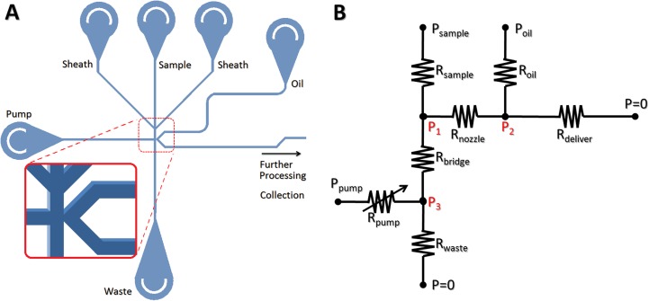
The microfluidic on-demand droplet processors were built with two common microfabrication materials: glass and poly(dimethylsiloxane) (PDMS), respectively. Figure 1(a) illustrates a schematic of the processors. The glass device for generating droplets was made using standard photolithography and chemical etching by Caliper Life Sciences (Mountain View, CA). Flow channels were designed with a line-width of 10 μm on the photomask so that their maximum width after etching would be 70 μm and their depth would be 30 μm. The PDMS droplet processors were fabricated by conventional soft lithography method.25 SU-8 25 photoresist (MicroChem) was spin-coated onto silicon wafers and patterned by UV exposure (Karl Suss MA/BA-6 aligner) using a transparency photomask. The wafers then were immersed in SU-8 developer (MicroChem) for designated time and dried. The master molds were put in a vacuum desiccator with a drop of (tridecafluoro-1,1,2,2-tetranydrooctyl)-1-trichlorosilane (UCT) for 15 min for silanization. Then a 10:1 (w/w) mixture of RTV615A (Momentive) and curing agent, degassed under vacuum, was poured onto the master mold and cured at 75 °C for 2 h. After obtaining the PDMS replica, inlets/outlets holes were punched using a 0.75 mm-diameter Uni-Core biopsy punch. The PDMS channels were irreversibly bonded with a glass slide by a conventional oxygen plasma bonding method followed by overnight curing at 75 °C to enhance bonding strength. Finally, the flow channels were treated with a commercial surface coating agent (PicoGlide®, Dolomite) to ensure fluorophilic channel surfaces and subsequently flushed with nitrogen. The final dimensions of the PDMS channels were 70 μm in width and 30 μm in depth.
FIG. 1.
(a) A schematic of an on-demand droplet processor. The on-demand droplet generation system consists of four different aqueous phase inlets, one continuous oil phase inlet, one waste outlet, and one droplet collection outlet (not shown). Detailed structures' channel intersection with a droplet-forming nozzle is shown in the zoomed-in inset (not to scale). (b) A simplified electrical circuit analogous model. Fluidic channels and tubing constitutes 1 variable resistance for Rpump and 6 constant resistances for the others. Resistances in sheath flows are combined into a single sample resistance. During operation, 3 input pressures are controlled and internal pressures at 3 different locations (P1, P2, P3) determines the size of droplets generated, flow rates of droplets, and droplet contents.
B. Device operation
For the continuous phase, fluorinated oil (FC-40, 3M) containing 0.8% (w/w) surfactant (PicoSurf®, Dolomite) was used. Its interfacial tension with water was estimated to be ∼5 mN/m for calculations.26 Droplet formation in our device worked well for a wide range of surfactant concentrations (0.3–5 wt. %) in oil. The working range of water/oil interfacial tension typically ranged from 2 to 20 mN/m. The aqueous and oil phases were injected into the microfluidic channels via polytetrafluoroethylene [PTFE] tubing (1/32″ OD). For glass devices, custom designed fittings and a custom designed Delrin holder were used for air-tight mounting. All aqueous and oil phases were driven by pressurizing off-chip reservoirs with nitrogen using 0–15 psi scalable pressure modulators (Pneutronics) and the typical range of operation was 2–5 psi. All the inputs were independently controlled for (i) aqueous sample flow, (ii) carrier oil, (iii) pumping fluid, and (iv) injection fluid. The on-demand pumping fluid was connected to a microdispensing valve (Lee Company), controlled by a PC with a custom program for LabVIEW software. For imaging experiments, commercial food dyes in different colors were diluted for use. Microscopic observations were made using an Olympus IX71 inverted microscope with Andor Clara interline CCD camera.
For particle detection, laser-induced fluorescence and forward scatter were detected using photomultiplier tubes (PMTs) and a LabView program controlled the microdispensing pump. However, demonstration of on-demand triggering of the micro-dispensing pump was done without the PMT signals. The LabView controller simulated actuation of the pump at predetermined times (randomly chosen or periodic). To determine the recovery time (minimal temporal gap between actuation) of the pump, LabView actuated the pump periodically at clock cycles of 0.5–10 Hz.
C. Escherichia coli encapsulation
Recombinant Green Fluorescent Protein (GFP)-expressing E. coli cells were incubated in Luria-Bertani (LB) medium at 37 °C. After incubation, the medium was completely removed by multiple centrifugation steps and the pelleted E. coli cells were re-suspended in nuclease-free water to form the aqueous phase.
III. RESULTS
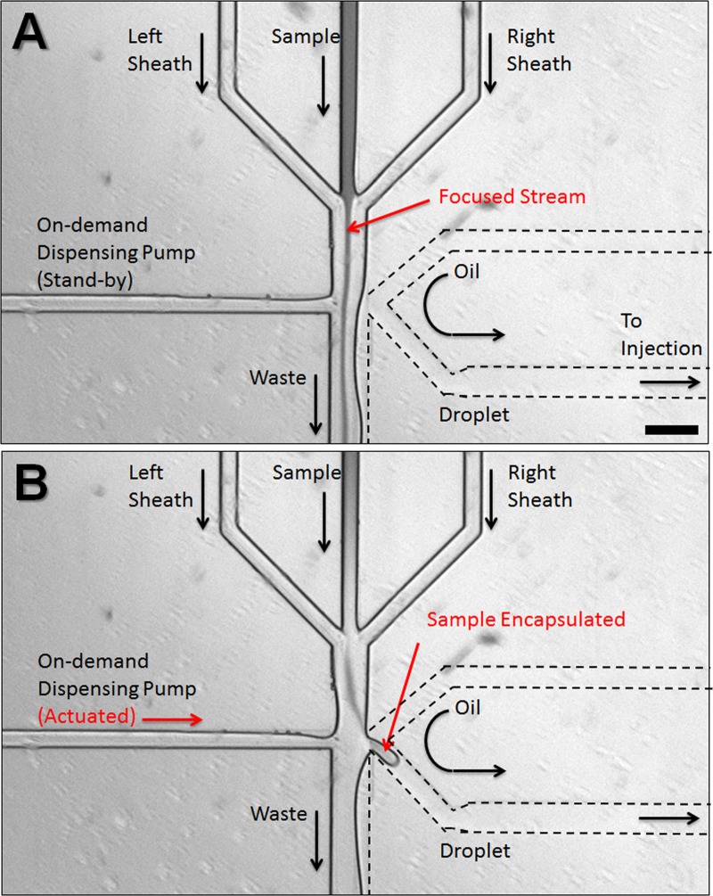
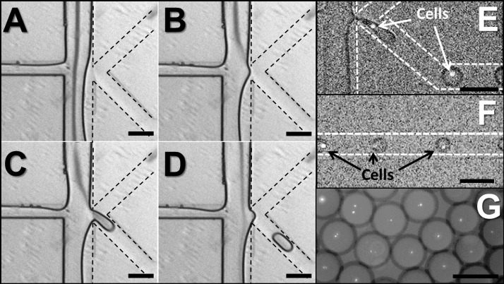
The on-demand droplet generation process in our device is shown in Figure 2. In the stand-by state, the aqueous sample flow is driven down to the waste collection outlet, and no droplets are produced. A small portion of oil phase may enter into the waste route, with a well-defined (stratified) interface. The rest of the oil phase is directed to the main processing channel but carries no droplets (Figure 2(a)). Upon a successful detection of a target particle to be encapsulated in a droplet (or at predetermined times), the computer control program triggers the microdispensing pump connected to the sample reservoir. In the actuated state, the sample flow channel is rapidly pressurized with the dispensing fluid (incompressible liquid from microdispensing pump), forcing the sample flow to intrude into the adjacent oil phase flow through a narrow nozzle. Due to the Rayleigh instability of aqueous phase in the oil phase, a droplet forms and is carried into the main processing channel (Figure 2(b)). Note that regardless of the actuation strength, the flow rate of the oil phase must be balanced with that of the sample flow to achieve a stable stand-by state where the two-phase interface is formed near the nozzle. When the balance is disrupted, either no droplets will be formed on actuation (oil flow rate too high) or the system becomes a regular T-channel passive droplet generator (oil flow rate too low). Figures 3(a)–3(d) show the image sequence of droplet production from stand-by state through actuation back to stand-by. Once the sample flow is pressurized with dispensing fluid, a hemidroplet begins to grow at the narrow opening (Figure 3(b)). This interfacial movement then causes a sudden increase of Laplace pressure at the hemidroplet interface as its effective curvature radius () decreases, where and is the interfacial tension between the two phases. When the dispensing pressure is not high enough to overcome the Laplace pressure, the hemidroplet interface is retracted without making a droplet to the stand-by state. With sufficiently high pumping pressure, the sample fluid elongates into the oil phase with the effective radius increased (Figure 3(c)). Because of the increased radius, the Laplace pressure at the interface is reduced. Consequently, the elongated hemidroplet loses its potential to be retracted to the aqueous phase and instead stays in the oil phase. When a sufficient amount of the aqueous fluid intrudes into the oil phase, the hemidroplet loses its tail to reduce its interfacial tension and becomes a fully separated droplet. When the hemidroplet remains unseparated due to insufficient volume of aqueous fluid, droplets still can be produced upon closing pump actuation. The pumping pressure is then quickly withdrawn, resulting in sudden necking of the hemidroplet, which leads to another Laplace pressure build-up in the opposite direction (against droplet retraction). Finally, the shear stress on the elongated hemidroplet by the continuous oil phase causes the final breakoff of the droplet by pinching off the neck (Figure 3(d)). This droplet generation can be controlled by varying pumping pressure and actuation duration, which in combination affect the size of droplets and recovery time back to stable stand-by state for subsequent actuations. For higher pumping pressure and longer actuation duration, the system requires more recovery time. In typical conditions, glass devices tend to have recovery time of up to 100 ms while PDMS devices with the same geometry recover within 250 ms, enabling droplet generation at rates of 4–10 Hz. Longer recovery time for PDMS devices may be attributed to the more elastic substrate acting as a fluidic capacitor. To obtain PDMS devices with shorter recovery time, the substrate can be cured using higher amount of crosslinker than the standard protocol to yield a stiffer device (data not shown). Successive generation of droplets during the recovery time is still possible, but residual pressure from the prior actuation may affect the controllability, yielding a larger droplet or a train of multiple droplets. This droplet generation rate at 4–10 Hz is not comparable to that of high-throughput passive droplet generation systems that typically produce hundreds to thousands of droplets per second, but the on-demand nature of our system has an inherent limitation of speed due to the need for recovery time. However, on-demand generation enables more versatile controls in the course of droplet processing, since a single droplet can be treated individually and independently for sufficient time without interference from the subsequent droplets. Rare cell encapsulation on demand is demonstrated in Figures 3(e) and 3(f) using GFP expressing E. coli cells in the aqueous flow.
FIG. 2.
FIG. 3.
Droplet generation and cell encapsulation. Image sequence ((a)-(d)) of on-demand droplet production from stand-by state through actuation back to stand-by. (a) Stand-by state: aqueous phase and oil phase flow in parallel and form a stable interface. (b) Actuation state Initiation: due to the pressurized aqueous phase, the aqueous phase is directed into the oil phase. (c) Actuation state maturity: a hemidroplet grows at the narrow nozzle and elongates with a narrow neck developing. (d) Actuation state termination: the hemidroplet loses its potential to be retracted, causing the neck to be pinched off. The liberated droplet flows in the oil phase. (e) GFP-expressing E. coli cells are being encapsulated in aqueous droplets. (f) Droplets each containing a single E. coli cell flow down the channel for subsequent reagent injection. (g) Collection of droplets containing a single E. coli cell. Scale bars represent 100 μm.
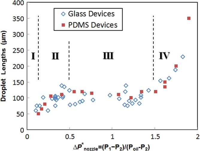
Over a wide range of operational pressures for the aqueous/oil phases and the dispensing fluid, this platform generates droplets of fairly uniform sizes for both glass and PDMS devices, unless the dimensions of the channels significantly change. As previously reported,26 the size of the droplets can be adjusted by changing the ratio of flow rates of the aqueous phase and carrier oil phase. Unlike regular passive T-channel systems, however, our system employs an active actuator that aperiodically changes internal pressures and their corresponding flow rates everywhere. Figure 1(b) shows an electrical circuit that is analogous to our fluidic system. Geometric dimensions of the channel define their constant fluidic resistances, except for 1 variable resistance for the channel connecting to the on-demand dispensing pump. When the system is at stand-by state, the valve is closed and Rpump becomes infinite. When the valve is open for actuation, Rpump recovers its geometrically defined constant value. This sudden decrease of resistance tends to cause overshot flows momentarily, but the system quickly returns to its steady state. This variable resistance model also can be represented by a resistance/switch model, yet a switch model requires two different sets of equations to solve for ON and OFF switch states, respectively. At normal operation conditions where Psample is comparable with Poil, oil streams partially intrude into the waste route because of its lower flow resistance. When Psample is much higher than Poil, aqueous streams overflow across the nozzle into the main channel. In such cases, the system becomes a passive droplet generator that can produce hundreds of droplets per second continuously. When Psample gets even higher, the aqueous stream and the oil stream form parallel flows with a horizontal interface at the middle of the channel width. When Psample increases further, it eventually stops the oil stream or makes it reflux to the oil inlet. Once the three input pressures are set for operation, internal pressures at three different locations (P1, P2, P3) can be calculated and they determine flow rates for droplet generation at the nozzle as well as injection capability. Specifically, the pressure difference over the nozzle () is proportional to the flow rate of sample flow through the nozzle, which corresponds to the aqueous flow rate for regular passive T-channel systems. Figure 4 illustrates the dependence of the size of generated droplets on this nozzle pressure difference, for a pumping duration of 1 ms for every actuation. Depending on the nozzle pressure, there are clearly four distinct regimes for droplet generation, which are unique for our on-demand droplet generation. In the first regime where the normalized pressure difference , the flow rate of sample through the nozzle becomes very slow compared to that of the oil phase. Because a hemidroplet grows extremely slowly during the actuation, it never reaches a stable spherical shape until the actuation ends, and thus will be retracted to the aqueous phase due to the backward Laplace pressure at the interface. By increasing the duration of actuation, it is possible to produce small droplets in this regime. The second regime exists when . The slightly increased pressure difference enables a higher flow rate of sample during the actuation, which leads to the development of bigger hemidroplets, However, this inflow of aqueous fluid into the hemidroplets is still too slow to completely fill the droplet to reach the most stable size of droplets. As a result, a portion of a hemidroplet that has not returned to the aqueous phase upon stopping actuation remains in the oil phase, forming a partially stable small droplet (premature droplet). Within this “premature” regime, the size of droplet increases as increases. For the third regime (), the rate of filling the hemidroplets becomes well balanced with the rate of squeezing off the droplets. Once the growing droplet fills the cross-section of the channel, it becomes a mature droplet and its neck is quickly pinched off. The extra fluid in hemidroplets is retracted to the aqueous phase. The size of droplets in this “mature” regime is fairly uniform over a wide range of pressure differential. In the fourth regime where , significantly increased pressure difference causes much higher droplet filling rate compared to the shearing oil phase. Accordingly, due to the rapidly increasing amount of aqueous fluid in hemidroplets, the retraction of extra fluid is prevented, resulting in a proportional increase in the size of droplets (overmature droplets). These droplet generation behaviors for the last two regimes are in good agreement with the previous reports on passive T-channel systems,27 except that our system enables production of more uniform size of droplets over a wider range of operation because our system is more tolerant of extra fluid in growing hemidroplets. Although our on-demand system functions very similarly to passive T-channel systems during the actuated state, the on-demand nature contributes to the first two unique regimes, mainly because the existence of the low resistance waste route for the aqueous phase significantly affects the droplet formation process.
FIG. 4.
Measured lengths of on-demand generated droplets in devices in two different materials: glass (empty diamonds) and PDMS (solid squares), respectively. The channel widths at the droplet generation junction are identically 70 μm for both devices. The duration of on-demand actuation is set constant at 1 ms for all data points. Four different regimes of operations depending on are denoted with Roman numbers: no droplets (I), premature droplets (II), mature droplets (III), and overmature droplets (IV).
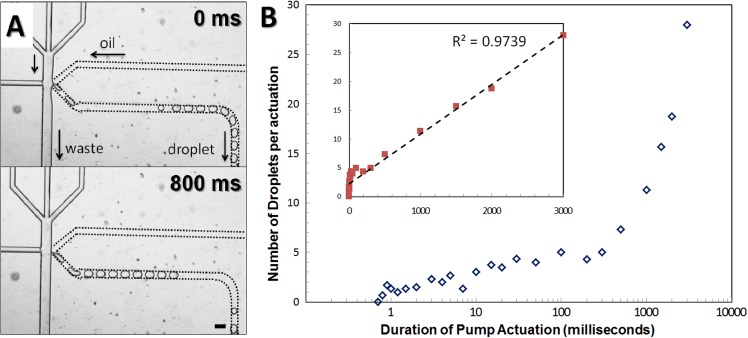
Droplet generation is also highly dependent on the duration of pump actuation. When the actuation is maintained for very short time (1 ms), the pumping pressure vanishes quickly without changing the nozzle pressure at all. In this case, there is insufficient aqueous fluid supplied to the oil phase, and no droplet is formed. Depending on applied pressures and channel geometry, there exist critical thresholds for actuation time to produce a droplet. Actuation longer than these thresholds apparently directs more aqueous fluid into the oil phase. Infinitely, long actuation (no stand-by state) allows permanent redirection of the aqueous phase into the oil phase and thus transforms the on-demand system into a passive T-channel droplet generator. In general, influences of the longer actuation on droplet generation are subject to the material of devices. For glass devices, internal pressure development only depends on the compressibility of fluid inside, since both glass and tubing are almost inelastic. Thus, the pressure changes originated from actuation almost instantaneously adjust internal pressures and the adjusted pressures are well maintained during the entire course of actuation. In this case, is independent of the duration of actuation and the size of droplets does not change. The more fluid coming to the oil phase then results in a train of uniformly sized droplets just like for a short-term operation of a passive T-channel system (Figure 5(a)).28 Note that the first generated droplet in a train is often larger than the following droplets, and this may result from the momentary flow overshoot upon actuation. More interestingly, the last one or two droplets in a train may become smaller, since it is likely that gradual pressure decrease at the end of actuation or during recovery time can cause premature release of one or two droplets. For sufficiently long duration of actuation (>100 ms), the number of droplets generated in a train each actuation is in direct proportion to the amount of intruded aqueous fluid for the actuation time. For a fixed pressure, the number of droplets is then linearly proportionate to the duration of actuation (inset plot in Figure 5(b)). However, if the actuation lasts shorter than typical internal pressure recovery time (∼100 ms) in glass devices, the duration of actuation will have less effect on the number of droplets produced per actuation, showing less steep increase for time less than 100 ms (main plot in Figure 5(b)). In more elastic PDMS devices, however, much longer actuation time is required to produce multiple droplets in a single actuation. If actuation takes longer time, there can be internal pressure buildup in the channel because of the high elasticity of PDMS. This built-up pressure then increases tentatively for quite a long time, which rather leads to increases on the size of single droplets that corresponds to the fourth “overmature” regime in Figure 4.
FIG. 5.
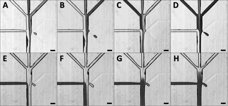
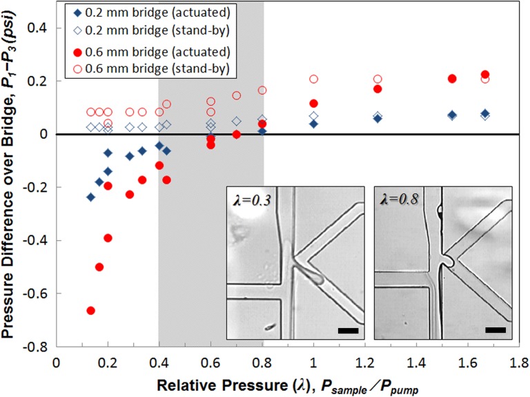
Contents of an aqueous droplet can be fine-tuned by including a gap between the on-demand pumping channel and the droplet generation nozzle or simply by controlling the flow rates of the aqueous solutions. Our current device design is capable of mixing four different aqueous fluids in a single droplet at different ratios. Figures 6(a)–6(d) show how we set different aqueous streams for simultaneous encapsulation into a droplet. Three vertical dye streams with distinct concentrations enter a droplet on actuation and undergo rapid convection-aided mixing in a flowing droplet. Since the pumping direct the fluids horizontally toward the nozzle, all three vertical streams are squeezed into a droplet with the nearest stream encapsulated most. Thus, it is possible to fine-tune contents simply by changing the order of vertical streams or by adjusting their flow rates. The fourth fluid available for mixing in a droplet with our design is the pump dispensing fluid. Although the primary purpose of this fluid is to provide a horizontal thrust to sample streams, it can be also partially incorporated into a droplet when the pumping causes a pressure overshoot or when high pump pressures are maintained for actuation. For weak pumping pressures (Figures 6(e) and 6(f)), the dispensing fluid provides only a horizontal push without entering a droplet. At higher pumping pressures (Figures 6(g) and 6(h)), the fluid begins intrusion. While the sample and sheath streams keep being removed to the waste route without actuation, the dispensing fluid is not removed during the stand-by state. Rather, it participates in droplet formation only when there is an active actuation, which implies that this method of encapsulation can be advantageous for expensive samples, hazardous reagents, or already concentrated analytes. However, it should be noted that sometimes this dispensing fluid must be avoided in a droplet because it can dilute the samples, lowering their effective concentration. More importantly, the dispensing fluid can be a source of contamination for biological applications. In such cases, since contamination may occur with an extremely small amount of contaminants transferred to the sample fluid either before or after droplet formation, there is a need to completely (spatially or physicochemically) separate the dispensing fluid from sample streams. One simple method to achieve this separation is to use oil as the dispensing fluid.28 Naturally forming oil-water interface will essentially prevent contaminants from contacting aqueous streams. This oil pumping method is particularly suitable for those applications where no mixing within droplets is required yet complete sample isolation is desirable. However, to use an aqueous phase in the dispensing fluid instead, there must be a special structure to prevent it from merging into droplets on actuation. By employing a reverse-direction bridge between the dispensing channel and the droplet generation nozzle, it is possible to impose an extra flow resistance (Rbridge; see Figure 1(b)) and a spatial and temporal gap between the dispensing fluid and droplets. This bridge structure can minimize the effect of overshoots on actuation, preventing the dispensing fluid from merging with sample streams within moderate operational conditions. Figure 7 shows the pressure variations around the bridge estimated by flow resistance analysis for stand-by and actuation states, depending on the bridge length. The pressure difference () over the bridge between the droplet formation nozzle (P1) and the dispensing channel (P3) was calculated for various operational conditions, which are represented by relative pressure (λ = P1/P3), the ratio of pressures applied to the sample flow and to the dispensing pump. For low λ values, the strength of the dispensing pump becomes greater, whereas the pumping strength decreases as λ increases. During the stand-by state, remains positive, which indicates forward (downward) flow over the bridge. Upon actuation by a strong pump (low λ), may become negative, exhibiting reverse backward (upward) flow over the bridge. This reverse flow then causes partial inclusion of the dispensing fluid into a newly forming droplet. Figure 7 shows huge differences in between the stand-by and the actuation state for low λ (<0.4), which indicates that the actuation of the pump with a high pressure is actively involved in droplet formation process. For a short period of actuation time, residual sample flow that has occupied the bridge during the stand-by state will be pushed back up to the nozzle, participating in droplet formation. Prolonged actuation will eventually cause partial incorporation of the dispensing pump fluid into a developing droplet, which must be avoided for contamination control; otherwise, intrusion of the dispensing fluid can be intended for mixing simply by increasing the pumping pressure. On actuation, the dispensing fluid will reverse the flow and partially enter the droplet along with sample streams (Figure 7, left inset). Note that does not change much from stand-by to actuation state for high λ (>1), mainly because the weak pumping pressure hardly contributes to pressurization of the bridge. Such weak actuation thus may not be able to initiate formation of a hemidroplet into the oil phase. The shaded region in Figure 7 represents the optimal operational range (0.4 < λ < 0.8) of applied pressures for stable on-demand droplet generation, when the pressure applied to oil phase (Poil) is comparable to the sample pressure (Psample). Within this range of operation, the system shows sufficiently high actuation strength to drive droplet generation with good controllability of the size and number of droplets, yet at the same time, it can minimize the adverse overshoot effects to prevent possible contamination and uncontrollable burst of droplets (Figure 7, right inset). This optimal range of the relative pressure (λ) may be shifted when the bridge length is significantly different.
FIG. 6.
FIG. 7.
Droplet generation with dilute samples often yields overwhelmingly large number of empty droplets and only a small number of positive droplets. Despite the high frequency of droplet generation of regular T-junction system, its effective frequency for positive droplets may become significantly lower, depending on the concentration in the original sample. For samples of a concentration less than 0.01 copies per droplet volume, our device will thus have higher throughput than regular T-junction followed by sorting (post-sorting). The other advantage of our system is the requirement for a simpler detection scheme—detecting a particle before its encapsulation required in our device is easier than detecting it in a droplet for the post-sorting detection. Particles in a large droplet rapidly circulate inside the droplet, such that detection at a single focused spot is inefficient. A tailored geometry to minimize circulation or force particles to traverse a detection volume can improve the likelihood of detection, but this increases flow resistance, adversely affecting sorting performance. Our proposed system performs detection (and sorting) prior to droplet generation and takes advantage of hydrodynamic focusing to narrow down detection area without sacrificing flow resistance. Another complication of a typical droplet sorting may occur due to the flow of large number of droplets in a short time in the waste route. Too many droplets may cause congestion and increase flow resistance in the waste outlet, resulting in redirection of negative droplets into the positive outlet. Finally, current post-sorting systems must be built on a separate chip, because of the complicated droplet route (generation, spacing, bifurcation). For multi-step analysis where droplet merging or injection is required, a third chip may be required. On the other hand, droplets in our system flow along a single route, which enables incorporation of other droplet processing units on the same chip.
IV. CONCLUSIONS
We have presented an on-demand droplet generation system on a single chip for multiple steps of bioassays that enables versatile droplet generation on demand with fine-tunable control. On-demand droplet generation is based on the actuation of a microdispensing pump connected to a pressure source. The system is normally under a stand-by state but will be actuated only when there is an immediate need for droplet generation such as detection of particles of interest to be encapsulated for reaction. The actuation is entirely automated by computer software. These droplet generation devices have been constructed in glass and PDMS, which are the most frequently used materials for microfabrication, and we have proven that both materials are well suited for on-demand control, although they behave differently at prolonged actuation. The throughput of the devices presented is appropriate for many multi-step bioassay applications that require a high level of control for individual steps and where there is a need to increase the concentration of extremely dilute samples like individual cells or microbes. We have also demonstrated versatile methods to control contents of an aqueous droplet. Our current device can mix four different aqueous fluids in a single droplet at different ratios. In combination with optical detection, our on-demand droplet generation technique will facilitate the development of various droplet-based microfluidic systems for multiple purposes including high throughput screening, enzymatic assays and uncultivated cell studies, and genomic assays.
ACKNOWLEDGMENTS
We thank David Brekke for his support and guidance for experiments and David Heredia for consistent assistance with clean room use. We are also grateful to Matthew Piccini, Ben Schudel, Mais Jebrail, Junyu Mai, and Mary Bao Trang for helpful conversations and help with the laboratory work. We also acknowledge Victoria VanderNoot for valuable advice. Financial support for the work was provided by the grants: R01 DE020891, funded by the NIDCR; ENIGMA, a LBNL Scientific Focus Area Program supported by the U.S. Department of Energy, Office of Science, Office of Biological and Environmental Research; and the DOE Joint BioEnergy Institute supported by the US DOE, Office of Science, Office of Biological and Environmental Research through Contract No. DE-AC02-05 CH11231 (LBNL). Sandia is a Multiprogram Laboratory operated by Sandia Corporation, a Lockheed Martin Company, for US DOE's Nuclear Security Administration under Contract No. DE-AC04-94AL85000.
REFERENCES
- 1.Teh S. Y., Lin R., Hung L. H., and Lee A. P., “ Droplet microfluidics,” Lab Chip 8(2), 198–220 (2008). 10.1039/b715524g [DOI] [PubMed] [Google Scholar]
- 2.Huebner A., Sharma S., Srisa-Art M., Hollfelder F., Edel J. B., and Demello A. J., “ Microdroplets: A sea of applications?” Lab Chip 8(8), 1244–1254 (2008). 10.1039/b806405a [DOI] [PubMed] [Google Scholar]
- 3.Pompano R. R., Liu W., Du W., and Ismagilov R. F., “ Microfluidics using spatially defined arrays of droplets in one, two, and three dimensions,” Annu. Rev. Anal. Chem. 4, 59–81 (2011). 10.1146/annurev.anchem.012809.102303 [DOI] [PubMed] [Google Scholar]
- 4.Rhee M. and Burns M. A., “ Drop mixing in a microchannel for lab-on-a-chip platforms,” Langmuir 24(2), 590–601 (2008). 10.1021/la702575j [DOI] [PubMed] [Google Scholar]
- 5.Guo M. T., Rotem A., Heyman J. A., and Weitz D. A., “ Droplet microfluidics for high-throughput biological assays,” Lab Chip 12(12), 2146–2155 (2012). 10.1039/c2lc21147e [DOI] [PubMed] [Google Scholar]
- 6.Simon M. G., Lin R., Fisher J. S., and Lee A. P., “ A Laplace pressure based microfluidic trap for passive droplet trapping and controlled release,” Biomicrofluidics 6(1), 014110 (2012). 10.1063/1.3687400 [DOI] [PMC free article] [PubMed] [Google Scholar]
- 7.Brouzes E., Medkova M., Savenelli N., Marran D., Twardowski M., Hutchison J. B., Rothberg J. M., Link D. R., Perrimon N., and Samuels M. L., “ Droplet microfluidic technology for single-cell high-throughput screening,” Proc. Natl. Acad. Sci. U.S.A. 106(34), 14195–14200 (2009). 10.1073/pnas.0903542106 [DOI] [PMC free article] [PubMed] [Google Scholar]
- 8.Li W., Pham H. H., Nie Z., MacDonald B., Guenther A., and Kumacheva E., “ Multi-step microfluidic polymerization reactions conducted in droplets: the internal trigger approach,” J. Am. Chem. Soc. 130(30), 9935–9941 (2008). 10.1021/ja8029174 [DOI] [PubMed] [Google Scholar]
- 9.Eastburn D. J., Sciambi A., and Abate A. R., “ Picoinjection enables digital detection of RNA with droplet RT-PCR,” PLoS One 8(4), e62961 (2013). 10.1371/journal.pone.0062961 [DOI] [PMC free article] [PubMed] [Google Scholar]
- 10.Zheng B., Tice J. D., and Ismagilov R. F., “ Formation of arrayed droplets of soft lithography and two-phase fluid flow, and application in protein crystallization,” Adv. Mater. 16(15), 1365–1368 (2004). 10.1002/adma.200400590 [DOI] [PMC free article] [PubMed] [Google Scholar]
- 11.Shestopalov I., Tice J. D., and Ismagilov R. F., “ Multi-step synthesis of nanoparticles performed on millisecond time scale in a microfluidic droplet-based system,” Lab Chip 4(4), 316–321 (2004). 10.1039/b403378g [DOI] [PubMed] [Google Scholar]
- 12.Chang C., Sustarich J., Bharadwaj R., Chandrasekaran A., Adams P. D., and Singh A. K., “ Droplet-based microfluidic platform for heterogeneous enzymatic assays,” Lab Chip 13(9), 1817–1822 (2013). 10.1039/c3lc41418c [DOI] [PubMed] [Google Scholar]
- 13.Thorsen T., Roberts R. W., Arnold F. H., and Quake S. R., “ Dynamic pattern formation in a vesicle-generating microfluidic device,” Phys. Rev. Lett. 86(18), 4163–4166 (2001). 10.1103/PhysRevLett.86.4163 [DOI] [PubMed] [Google Scholar]
- 14.Perroud T. D., Meagher R. J., Kanouff M. P., Renzi R. F., Wu M., Singh A. K., and Patel K. D., “ Isotropically etched radial micropore for cell concentration, immobilization, and picodroplet generation,” Lab Chip 9(4), 507–515 (2009). 10.1039/b817285d [DOI] [PubMed] [Google Scholar]
- 15.Anna S. L., Bontoux N., and Stone H. A., “ Formation of dispersions using ‘flow focusing’ in microchannels,” Appl. Phys. Lett. 82(3), 364–366 (2003). 10.1063/1.1537519 [DOI] [Google Scholar]
- 16.Guillot P., Colin A., Utada A. S., and Ajdari A., “ Stability of a jet in confined pressure-driven biphasic flows at low Reynolds numbers,” Phys. Rev. Lett. 99(10), 104502 (2007). 10.1103/PhysRevLett.99.104502 [DOI] [PubMed] [Google Scholar]
- 17.Gunther A. and Jensen K. F., “ Multiphase microfluidics: From flow characteristics to chemical and materials synthesis,” Lab Chip 6(12), 1487–1503 (2006). 10.1039/b609851g [DOI] [PubMed] [Google Scholar]
- 18.Baroud C. N., Gallaire F., and Dangla R., “ Dynamics of microfluidic droplets,” Lab Chip 10(16), 2032–2045 (2010). 10.1039/c001191f [DOI] [PubMed] [Google Scholar]
- 19.Seemann R., Brinkmann M., Pfohl T., and Herminghaus S., “ Droplet based microfluidics,” Rep. Prog. Phys. 75(1), 016601 (2012). 10.1088/0034-4885/75/1/016601 [DOI] [PubMed] [Google Scholar]
- 20.Fradet E., McDougall C., Abbyad P., Dangla R., McGloin D., and Baroud C. N., “ Combining rails and anchors with laser forcing for selective manipulation within 2D droplet arrays,” Lab Chip 11(24), 4228–4234 (2011). 10.1039/c1lc20541b [DOI] [PubMed] [Google Scholar]
- 21.Zeng S. J., Li B. W., Su X. O., Qin J. H., and Lin B. C., “ Microvalve-actuated precise control of individual droplets in microfluidic devices,” Lab Chip 9(10), 1340–1343 (2009). 10.1039/b821803j [DOI] [PubMed] [Google Scholar]
- 22.Zec H., Rane T. D., and Wang T. H., “ Microfluidic platform for on-demand generation of spatially indexed combinatorial droplets,” Lab Chip 12(17), 3055–3062 (2012). 10.1039/c2lc40399d [DOI] [PMC free article] [PubMed] [Google Scholar]
- 23.Lorenz R. M., Edgar J. S., Jeffries G. D. M., and Chiu D. T., “ Microfluidic and optical systems for the on-demand generation and manipulation of single femtoliter-volume aqueous droplets,” Anal. Chem. 78(18), 6433–6439 (2006). 10.1021/ac060748l [DOI] [PubMed] [Google Scholar]
- 24.Xu J. and Attinger D., “ Drop on demand in a microfluidic chip,” J. Micromech. Microeng. 18(6), 065020 (2008). 10.1088/0960-1317/18/6/065020 [DOI] [Google Scholar]
- 25.Whitesides G. M., Ostuni E., Takayama S., Jiang X. Y., and Ingber D. E., “ Soft lithography in biology and biochemistry,” Annu. Rev. Biomed. Eng. 3, 335–373 (2001). 10.1146/annurev.bioeng.3.1.335 [DOI] [PubMed] [Google Scholar]
- 26.Mazutis L. and Griffiths A. D., “ Selective droplet coalescence using microfluidic systems,” Lab Chip 12(10), 1800–1806 (2012). 10.1039/c2lc40121e [DOI] [PubMed] [Google Scholar]
- 27.Garstecki P., Fuerstman M. J., Stone H. A., and Whitesides G. M., “ Formation of droplets and bubbles in a microfluidic T-junction—Scaling and mechanism of break-up,” Lab Chip 6(3), 437–446 (2006). 10.1039/b510841a [DOI] [PubMed] [Google Scholar]
- 28. See supplementary material at http://dx.doi.org/10.1063/1.4874715E-BIOMGB-8-003403 for more detailed image sequences of multiple droplet generation and for strategies to prevent the pumping fluid from entering on-demand generated droplets.
Associated Data
This section collects any data citations, data availability statements, or supplementary materials included in this article.
Data Citations
- See supplementary material at http://dx.doi.org/10.1063/1.4874715E-BIOMGB-8-003403 for more detailed image sequences of multiple droplet generation and for strategies to prevent the pumping fluid from entering on-demand generated droplets.


