Abstract
The onset of thromboembolic phenomena in blood oxygenators, even in the presence of adequate anticoagulant strategies, is a relevant concern during extracorporeal circulation (ECC). For this reason, the evaluation of the thrombogenic potential associated with extracorporeal membrane oxygenators should play a critical role into the preclinical design process of these devices. This study extends the use of computational fluid dynamics simulations to guide the hemodynamic design optimization of oxygenators and evaluate their thrombogenic potential during ECC. The computational analysis accounted for both macro- (i.e., vortex formation) and micro-scale (i.e., flow-induced platelet activation) phenomena affecting the performances of a hollow-fiber membrane oxygenator with integrated heat exchanger. A multiscale Lagrangian approach was adopted to infer the trajectory and loading history experienced by platelet-like particles in the entire device and in a repetitive subunit of the fiber bundles. The loading history was incorporated into a damage accumulation model in order to estimate the platelet activation state (PAS) associated with repeated passes of the blood within the device. Our results highlighted the presence of blood stagnation areas in the inlet section that significantly increased the platelet activation levels in particles remaining trapped in this region. The order of magnitude of PAS in the device was the same as the one calculated for the components of the ECC tubing system, chosen as a term of comparison for their extensive diffusion. Interpolating the mean PAS values with respect to the number of passes, we obtained a straightforward prediction of the thrombogenic potential as a function of the duration of ECC.
Keywords: Computational fluid dynamics, Multiscale analysis, Extracorporeal circulation, Platelet activation, Thrombogenic potential
1 Introduction
In industry, the current design specifications for blood recirculating devices (BRDs) used in extracorporeal circulation (ECC) are mainly focused on macroscale parameters, such as the minimization of pressure losses and priming volumes, and on the optimization of gas and heat transfer efficiency (Haworth 2003). The typical industrial design approach is largely based on time-consuming and often inefficient empirical approaches, and the device fluid dynamics is mainly investigated using experimental techniques (Fiore et al. 1998; Mueller et al. 1998; Kawahito et al. 2001).
Currently, one of the major challenges in ECC device design is the minimization of flow-induced platelet activation, which is a major precursor of thromboembolic complications (Schaadt 1999). In comparison with hemolysis, platelet activation is responsible for the onset of thrombogenic phenomena that occur at shear stresses ten-fold lower than those responsible for red blood cell damage (Ramstack et al. 1979). Nonetheless, the research and development stage of BRDs has mostly been focused on the evaluation of the hemolysis, often neglecting the thrombogenic aspects (Bluestein 2006). Up to date, the risk of thrombus formation during ECC has been generally controlled by anticoagulant therapies, which in turn may induce further complications such as bleeding. The main efforts to reduce the need of anticoagulants have been spent toward surface-treatment strategies (Zimmermann et al. 2007; Niimi et al. 1999; Pappalardo et al. 2006). However, a wider-spectrum approach should require BRDs to be thoroughly optimized to minimize or eliminate flow conditions that cause shear-induced platelet activation.
Flow-induced platelet activation is a complex phenomenon, taking place at different length and time scales that are challenging to couple (Yamaguchi et al. 2010). Prior studies on BRDs for ECC focused on the experimental quantification of the effects of platelet activation, by measuring the dimension of platelet aggregates in centrifugal pumps (Tanaka et al. 2001), computing the progression of thrombus growth in hemodialyzers and oxygenators (Goodman et al. 2005) and comparing the formation of platelet microaggregates in centrifugal and roller pumps (Linneweber et al. 2002). However, at present, there is a lack of mechanistic insight into the factors that determine platelet activation in these devices.
In the last decade, computational fluid dynamics (CFD) methods have proven their effectiveness in the design process of a wide range of BRDs for ECC, such as pumps (Fiore et al. 2002; Legendre et al. 2008), oxygenators (Gage et al. 2002; Hormes et al. 2011), arterial filters (Fiore et al. 2009), and dialyzers (Eloot et al. 2002). The advantages of CFD reside in its capability to evaluate the performance of a device at an early stage of the design process, reducing the costs and time needed to manufacture and test physical prototypes (Verdonck 2002). The potentialities of the CFD approach, alone or in combination with other modeling techniques, were also proved in the investigation of multiscale blood-related phenomena (Vesentini et al. 2006; Fiore et al. 2006).
In the present study, we adopted a CFD-based strategy recently developed for the study of mechanical heart valves (Xenos et al. 2010; Alemu et al. 2010), in the perspective of guiding the design optimization of oxygenators in order to minimize their thrombogenic potential. Here, this method was applied to the evaluation of the thrombogenic potential of a prototype hollow-fiber membrane oxygenator with an integrated heat exchanger for ECC. The modeling strategy accounted for a macroscale quantification of the velocity and pressure fields, combined with a microscale analysis at the fiber level, and with a transient analysis based on a Lagrangian approach of the mechanical load history experienced by platelet-like particles. This information was then input into a mathematical damage accumulation model to obtain the platelet activation state as a function of the number of passes of the blood within the device.
2 Materials and methods
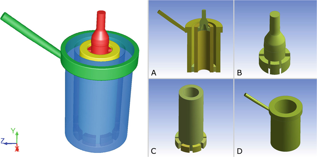
A prototype hollow-fiber membrane oxygenator for ECC, developed for research purposes, was analyzed in this work. The device consists of two concentric cylinders: an internal heat exchanger (HE) interfaced with an external membrane oxygenator (OXY), both made of polymeric hollow-fiber mats. A coaxial inlet region delivers the blood to the HE, while a manifold collects the blood from the OXY and channels it to the outlet (Fig. 1). The heating fluid and the oxygenating gas flow inside the hollow fibers of the HE and OXY regions, while blood flows outside of them. All fluids are separated by impermeable membranes and they never come into direct contact.
Fig. 1.
Left Three-dimensional model of the fluid domain inside the hollow-fiber oxygenator (OXY) with integrated heat exchanger (HE). The model is composed of four sections: inlet zone (red); HE bundle zone (yellow); OXY bundle zone (blue); and blood manifold and outlet (green). Right Longitudinal cross-section of the device (a); inlet zone with flow distributor (b); HE bundle with interface volumes (c); OXY, manifold and outlet (d)
The workflow was divided into three steps:
A CFD analysis was performed to compute the loading history experienced by the blood particles that flow within the device under working conditions.
The loading history was incorporated in a damage accumulation model in order to estimate the platelet activation state associated with blood passing through the device.
The flow-related thrombogenic risk of the device was compared with one arising from the tubing system of an ECC circuit.
2.1 CFD analysis
2.1.1 Macroscale steady-state analysis
A macroscale CFD simulation was performed to assess the pressure and velocity fields within the device and to determine the shear stress distribution. Blood was modeled as an incompressible Newtonian fluid with density ρ equal to 1,052 kg/m3 and viscosity η equal to 2.36 cP, which approximate the rheologic properties of blood at 34% hematocrit, a representative condition during ECC for cardiopulmonary bypass. The three-dimensional geometry of the device was discretized with 2.7×10⁶ tetrahedral elements and the quality of the mesh was assessed by checking the elements’ equiangle skewness (<0.83) and aspect ratio in the flow direction (<10). A structured hexahedral mesh was chosen for the inlet section, due to the presence of turbulence phenomena in this region and in order to reduce the numerical diffusion error. The number of mesh elements was increased using three progressively refined meshes, with about 7 × 10⁵, 1.3 × 10⁶, and 2.7 × 10⁶ elements each, until the difference between two meshes was considered small enough to represent a mesh-independent solution for our study, where the chosen criterion was a difference less than 2% in the flow variables distribution (i.e., velocity and pressure contours).
A velocity equal to 1.254 m/s, which corresponded to a blood flow rate of 5 L/min, was assigned to the inlet section. A zero pressure boundary condition was specified for the outlet. The SIMPLE method for pressure-velocity coupling with a second order upwinding scheme was adopted. Laminar flow conditions were assumed in the fiber bundles, while in the inflow and outflow zone, the viscous k-ω two-equation turbulence model with low Reynolds number corrections was adopted. A 5% backflow turbulent intensity (T.I.) with a 0.0092 m hydraulic diameter were set as boundary conditions for the turbulence model, where the latter corresponded to the diameter of the circular inlet and outlet conduits, while the former was calculated using the relationship T.I. = 0.16 • Re−1/8, as suggested in Varghese and Frankel (2003), Banks and Bressloff (2007), given a Reynolds number (Re) almost equal to 5,200. The convergence of the solution was controlled by setting the maximum values of the residuals to 10−4 for the mass and momentum equations and for the turbulence parameters k and ω.
Porous media model
A porous media model was adopted to simulate the fiber bundles in the HE and in the OXY regions in order to avoid the computational cost required to model each fiber in the device (Gage et al. 2002; Gartner et al. 2000; Graefe et al. 2010). The pressure losses were predicted by adding a momentum sink term S to the standard fluid flow equation:
| (1) |
where
| (2) |
The sink term is composed of two parts: the first term of Eq. (2) is representative for the viscous dissipations, while the second term accounts for the inertial effects. At low flow rates (Q < 6 L/min), the inertial effects can be neglected (Gage et al. 2002); therefore, the characteristics of the porous model depend only on its viscous resistance that was obtained from Darcy’s Law as follows:
| (3) |
where A is the transversal cross-section of the fiber bundle run through by the flow rate Q, ΔP is the pressure drop across the fiber bundle, and L is the length of the hollow cylinder.
The values of ΔP across the HE and OXY fiber bundles at different flow rates were obtained from experimental tests performed at the laboratories of Sorin Group Italia (Mirandola, Italy) to calculate the viscous resistances.
The device was modified in order to measure the pressure drops in the HE and in the OXY regions separately. Four access holes were created at the interface between the HE and the OXY and positioned at 90° from each other. The holes were connected to four pressure transducers, and the ΔP was measured with respect to the inlet.
The device was perfused with porcine blood at 34% hematocrit. Tests were performed at 37 °C with flow rates ranging from 2 to 6 L/min. A sample port, situated at the exit of the OXY fiber bundle, was used to measure the ΔP just before the manifold section, in order to isolate the contribution of the OXY bundle. The ΔP located at the inlet section were calculated considering a diverging expansion of the inlet conduct, from a diameter of 9.5 mm to a diameter of 20 mm, with an opening angle of 26° (Idelchik 1994). The pressure drops across the outlet section were calculated subtracting the previous contributions to the total ΔP.
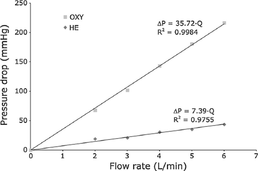
Experimental ΔP – Q data were fitted with a linear interpolation (Fig. 2) that provided viscous resistance values equal to 2.01 × 10⁸ 1/m2 in the HE (R2 = 0.9755) and to 2.25 × 10⁹ 1/m2 in the OXY (R2 = 0.9984). The porous media were considered isotropic; therefore, the viscous resistances were the same in every direction.
Fig. 2.
Experimentally measured pressure drops in the OXY and HE bundles obtained with porcine blood at 37 °C and 34% hematocrit
Scalar stress calculation
A user-defined function was implemented to calculate the value of the scalar stress according to the outcomes of the CFD simulation, and the total stress tensor τij, which included both the laminar and the turbulent stress components, was calculated as follows (Bird et al. 2002):
| (4) |
where u is the velocity vector and represents the turbulent Reynolds stress.
The Boussinesq approximation was used for the Reynolds stress component of the total stress tensor:
| (5) |
where k is the turbulent kinetic energy and ηt is the turbulent viscosity, whose values were extracted from the CFD simulation, while δij is the Kronecker’s delta. The components of the stress tensor were then rendered into a scalar stress value σ, based on the formulation outlined in (Apel et al. 2001):
| (6) |
A steady-state simulation was run using the commercial code ANSYS FLUENT v.12 on 6 parallel processors.
2.1.2 Lagrangian analysis of particle flow
Once convergence was reached for the steady-state solution, 2,200 spherical particles (diameter = 3 µm) with density ρ equal to 1,000 kg/m3 representing the platelets were injected into the fluid domain at the inlet section. A transient two-phase simulation was performed to evaluate the time-dependent shear stress acting on the platelets through a discrete phase modeling (DPM) approach, allowing identification of the trajectory and loading history of each particle flowing through the device in a Lagrangian reference frame. A fully coupled approach was adopted to account for the mutual influence between the fluid and the platelets. This approach solves the discrete and continuous phase equations alternately until the solutions in both phases converge.
2.1.3 Modeling of the viscous stresses through the fiber bundles
The porous media hypothesis is a good approximation to describe the behavior of the device on a macroscopic point of view. Anyway, this hypothesis is unsuitable to capture the actual microscopic flow phenomena that occur at the fibers level (Swartz and Fleury 2007). To assess the extent of the viscous stresses associated with these phenomena, a microscale CFD model was used to describe the shear stress τmicro acting on the platelets that flow within the two fiber bundles of the HE and the OXY at the microscopic level.
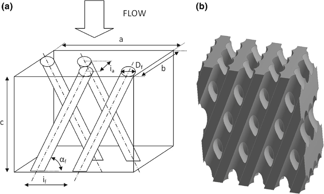
The geometry of the model represents the volume of blood flowing around the microfibers and is composed of a hexahedral bounding box from which the fiber volumes were subtracted, as schematized in Fig. 3. In particular, the fibers were knitted into a two-layer array in which two consecutive rows of fibers were alternatively inclined of an angle αf. The characteristic dimensions used to reconstruct the microscale models of the HE and OXY bundle subunits are summarized in Table 1.
Fig. 3.
a Schematic model of the fibers arrangement within a hexahedral bounding box, b Three-dimensional solid model of the blood volume around the microfibers
Table 1.
Characteristic dimensions used to reconstruct the microscale models of the HE and OXY bundle subunits
| HE | OXY | |
|---|---|---|
| Fiber external diameter Df | 0.55 mm | 0.48 mm |
| Inter-fiber distance If | 0.94 mm | 0.67 mm |
| Inter-array distance Ia | 0.45 mm | 0.30 mm |
| Fiber angle αf | 21° | 15° |
| Box width a | 3.75 mm | 4.04 mm |
| Box depth b | 1.90 mm | 1.50 mm |
| Box height c | 4.88 mm | 5.02 mm |
The geometrical models were discretized using a tetrahedral mesh with uniform element size equal to 0.05 mm and maximum skewness equal to 0.92. A mesh independence study was performed using three progressively refined meshes and verifying that no relevant differences (<2%) were found in the flow variables distribution (i.e., velocity and pressure contours) switching from a coarser to a finer mesh.
Fully developed laminar flow around the fibers was modeled using periodic boundary conditions that were assigned to all the external walls of the repetitive unit. The inlet/outlet periodic conditions were specified by setting the flow direction and imposing a mass flow rate of 2.95 × 10⁻⁴ kg/s in the HE fibers and of 7.85 × 10⁻⁵ kg/s in the OXY fibers, calculated as the fraction of the total mass flow rate (8.77 × 10⁻² kg/s) passing through the inlet sections of the respective microscale models.
In order to account for the non-Newtonian behavior of the blood at the microscale level, a user-defined function was adopted to describe the shear-dependence of blood viscosity. This function implements the power-law model proposed by Ballyk et al. (1994) that provides a reliable description of the non-Newtonian blood flow over a wide range of shear stresses (Johnston et al. 2004). The function was adjusted in order to set the value of the asymptotic high shear viscosity equal to that used in the macroscale simulation.
Steady-state Navier-Stokes equations were solved with the commercial code ANSYS FLUENT v.12 using the SIMPLE method for pressure-velocity coupling and a second-order upwinding scheme. Numerical convergence was evaluated by setting the maximum values of the residuals to 10−6 for the mass and momentum equations.
Transient analysis was performed following the same approach described in Sect. 2.1.2 for the macroscale model. About 2,000 platelet-like particles were injected into the fluid domain at the inlet section and their loading history was evaluated using a DPM approach.
For each particle trajectory, the value of the time-averaged scalar stress acting at the microscale level (τmicro) was calculated and added to the scalar stress σ computed in the macroscale simulation. In particular, once the particles entered the HE and OXY bundles, their macroscopic trajectories were associated with randomly selected microscopic trajectories in order to obtain a more accurate description of the thrombogenic potential in the porous regions.
2.2 Thrombogenicity risk evaluation in the device
The linear stress accumulation (SA) was calculated as the linear integral of the shear stress over time for each platelet trajectory obtained from the transient analysis (Xenos et al. 2010). The SA distribution represents a synthetic description of the overall flow-related thrombogenic potential of the device, that is, its thrombogenic “footprint”.
In this study, we used a state-of-the-art damage accumulation model (Nobili et al. 2008) to quantify the platelet activation state (PAS) deriving from the computed shear stress levels in the device. This model was thoroughly tuned on in vitro experiments conducted in a hemodynamic shearing device, capable of uniformly exposing platelets to dynamic shear stress waveforms.
The damage accumulation model establishes a correlation between the loading history τ(t), the time t, and the phenomenological response of the platelets. The PAS index was expressed as follows:
| (7) |
where PAS (t0) is the value of platelet activation at the starting time of observation t0, and a, b, C are constants fitted on experimental data and are equal to 1.3198, 0.6256, and 10−5, respectively. The integral sum inside the square brackets in Eq. (7) is representative of the mechanical load sustained by the platelets moving along a generic fluid trajectory, and it is calculated as the integral of the subsequent elementary contributions to damage acting in each infinitesimal time interval. PAS values range from 0, corresponding to no activation, to 1, which corresponds to the fully activated platelet state.
PAS, inclusive of the contribution of τmicro, was evaluated after multiple consecutive passes of the particles within the device, defined as the number of times a particle travelled along the whole device from the inlet to the outlet section; the trajectory followed by each particle was randomized in each successive pass in order to obtain a more realistic description of the phenomenon.
A power-law function PAS = c1Na, whose functional form was directly inferred from Eq. (7), was used to quantitatively describe the relationship between the PAS values and the number of passes (N); in this function, the exponent a was equal to that used in the damage accumulation model (1.3198), while the value of the constant parameter c1 was obtained from the least-square fitting of the computed PAS values evaluated at different number of passes.
2.3 Thrombogenicity risk evaluation in an ECC tubing system
A straight tube with diameter equal to 3/8” (9.525 mm) and length equal to 3 m, representative of the tubing system in an ECC circuit, was analyzed using a mathematical model. A flow rate equal to 5 L/min, set as a boundary condition for the model, yielded a turbulent flow regime within the tube (Re ≈ 5,000). An in-house developed code written with MATLAB programming language (MathWorks, Natick, MA) was used to determine the thrombogenic potential of the tubing system, which was then compared with that obtained for the device.
The MATLAB code was used to generate a uniform distribution of 10,000 particles on the inlet section of the tube. The position of each particle was identified by its radial coordinate r, and the trajectories of the particles along the tube were assumed rectilinear. Each particle was subjected to a constant velocity u = u(r) and to a shear stress τ(r) for a residence time tres(r) that were functions of r.
The shear stress profile was linear from the centerline to the wall and was defined as:
| (8) |
where R is the radius of the tube, V is the mean velocity and λ represents the friction coefficient, which was assessed using the empirical power-law correlation proposed by Blasius, where λ = 0.316•Re−0.25, accurate for Re > 3,000.
The residence time tres(r) of each particle within the tube was calculated as the ratio between the length L of the tube and the particle velocity u(r). The velocity profile was assumed from the von Karman-Prandtl logarithmic law:
where is the frictional velocity that determines the velocity scale; y+ = (R – r) u*.ρ/η is the dimension-less radial distance from the wall; and κ and A are universal constants equal to 0.4 and 5.5, respectively (Kim et al. 1987).
Thus, the SA of each particle in the tube was only a function of r and was calculated as:
| (9) |
The PAS distributions deriving from multiple consecutive passes of the platelets within the tube were calculated as described in Eq. (7) and compared to those obtained from the same number of passes within the device.
3 Results
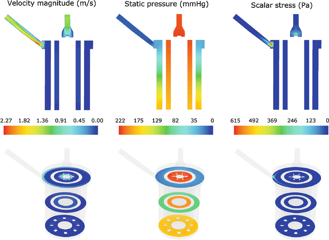
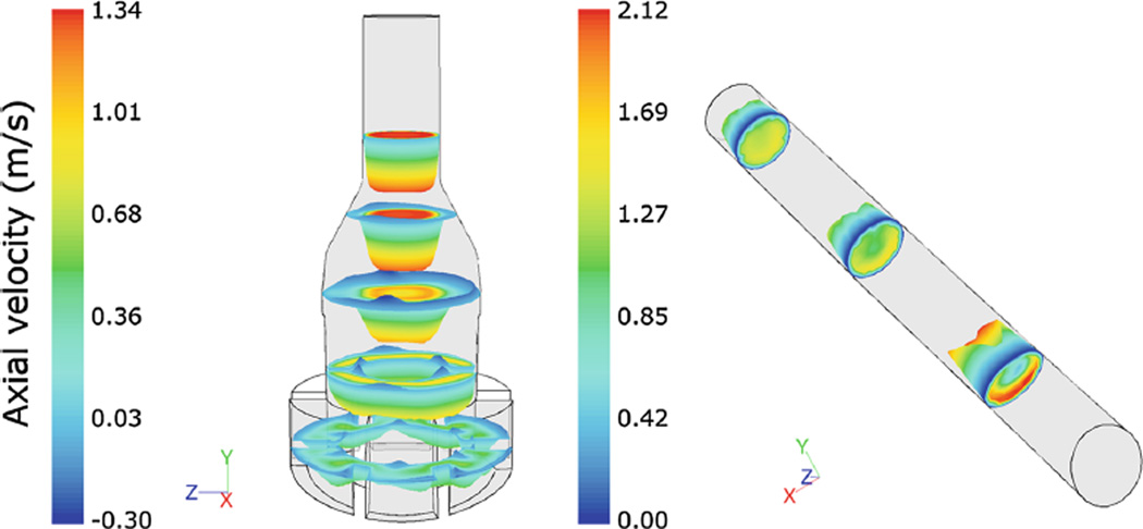
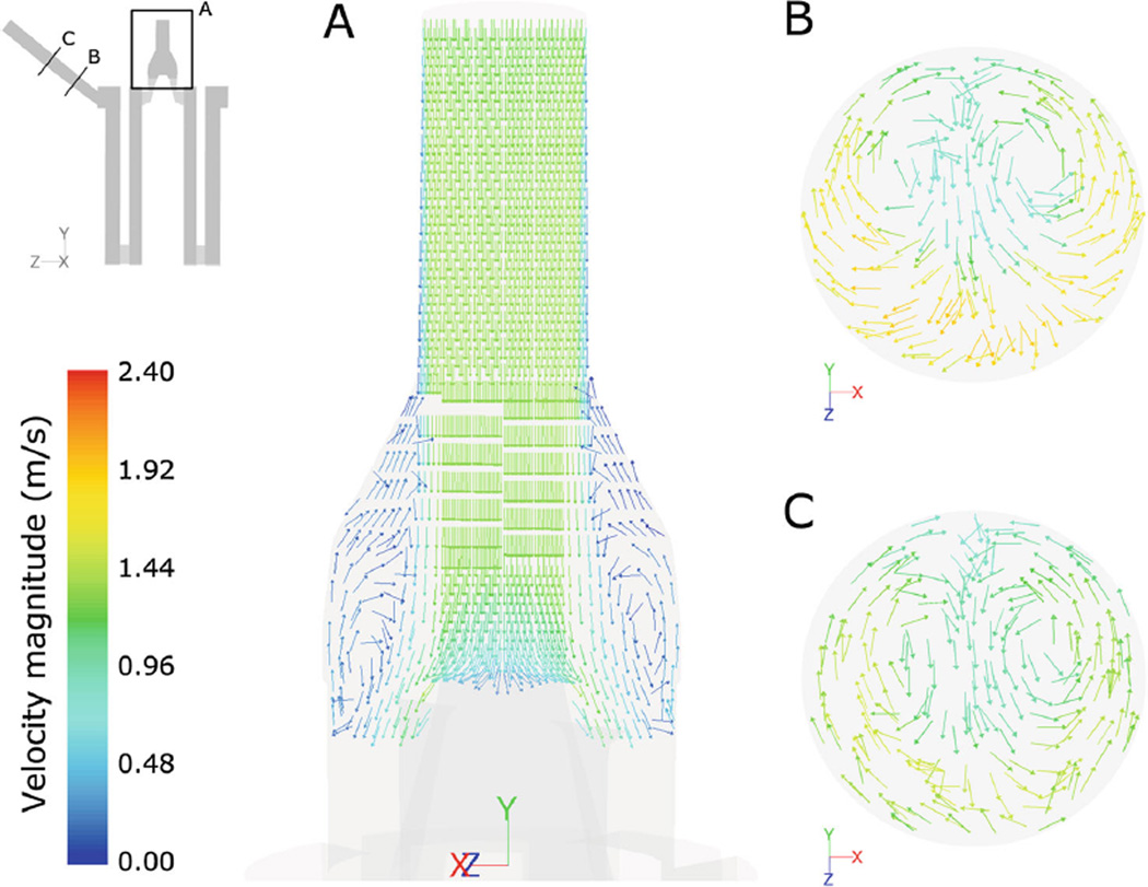
Steady-state computational results from the macroscale analysis were post-processed to extract the flow velocity patterns, the static pressure, and the scalar stress distribution (Fig. 4 a–c). Figure 4a shows a longitudinal cross-section of the device and displays the distribution of the fluid velocity magnitude. Maximum flow velocities (equal to 2.3 m/s) were located at the outlet section, while lower velocities were located in the porous zones, with a volume-averaged value of 0.076 m/s in the HE and 0.034 m/s in the OXY. Velocity profiles (Fig. 5) highlighted the presence of backflow phenomena in multiple sections of the inlet region and a skewed flow pattern in the outlet region, becoming more uniform toward the end of the conduit. As a consequence, blood recirculating areas were detected in the inlet region (Fig. 6a), due to the gradual enlargement of its section, and secondary flows were highlighted in the outlet region (Fig. 6b, c).
Fig. 4.
Contour maps of the velocity magnitude (left), static pressure (middle), and scalar stress (right) distribution in a longitudinal (top) and in three transversal (bottom) sections of the device
Fig. 5.
Velocity profiles colored by axial velocities (m/s) in multiple inlet (left) and outlet (right) sections
Fig. 6.
Velocity vectors, colored by velocity magnitude, in an inlet (a) and in two outlet sections (b, c) highlighting the presence of flow recirculation phenomena
The overall ΔP was equal to 211 mmHg (Fig. 4b), with 74% located in the OXY and 15 % located in the HE. The contribution of the inlet region to the overall ΔP was negligible (0.2%), while the outlet and the manifold contributed for 11% of ΔP.
The scalar stress contour map is displayed in Fig. 4c. The maximum values of the scalar stress were detected at the entrance of the outlet section (615 Pa) and at the distal part of the inlet region (300 Pa). The average scalar stress in the porous regions, before adding the contribution of τmicro, was equal to 0.05 Pa in the HE and 0.02 Pa in the OXY.
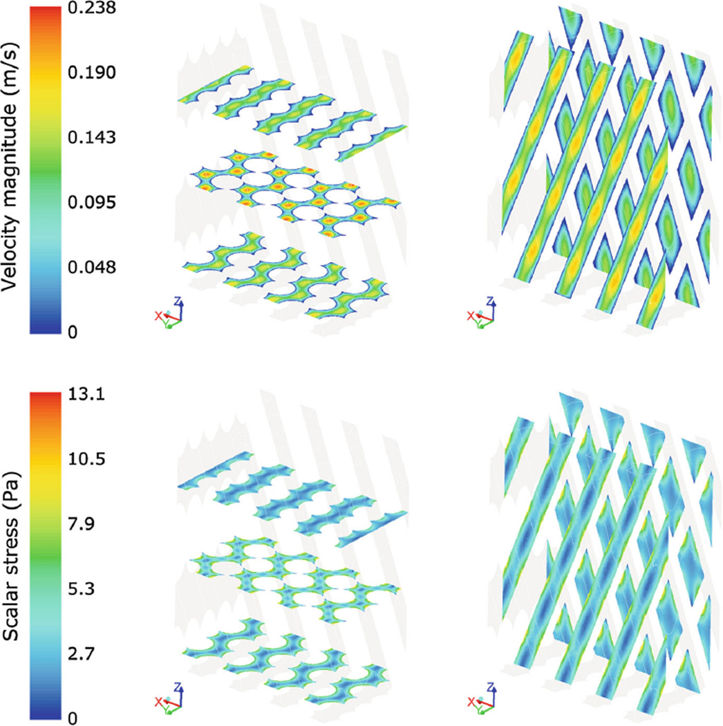
The contour maps of velocity and scalar stress distribution within the HE fibers obtained from the microscale analysis are displayed in Fig. 7. Maximum velocities were equal to 0.24 m/s in the HE bundle and to 0.19 m/s in the OXY bundle. The scalar stress within the fibers ranged from a minimum value of 0.093 and 0.18 Pa at the maximum distance from the fiber walls, to a maximum value of 13 and 23 Pa at the fiber walls in the HE and OXY, respectively. The pressure drops per unit of length in the microscale models of HE and OXY were equal to 45 × 103 Pa/m and 18 × 104 Pa/m, respectively; scaling those values over the total length of the porous bundles yielded a total pressure drop consistent with that obtained from the macroscale analysis.
Fig. 7.
Contour maps of velocity magnitude (top) and scalar stress (bottom) in three transversal and two longitudinal sections of the microscale HE model
The transient analysis allowed computation of the position and the scalar stress acting on each platelet-like particles seeded in the device, both in the macroscale and microscale analysis. Most of the platelets injected in the domain (>90 %) had escaped the device after six simulated seconds. The values of τmicro derived from the microscale analysis were added to the macroscale scalar stress values found in the HE and OXY regions; the median of the distribution of τmicro was equal to 3.84 Pa in the HE and to 4.53 Pa in the OXY.
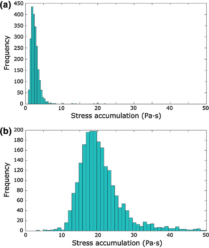
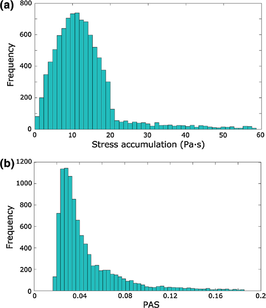
Figure 8 displays the histograms of the linear SA before and after adding the values of τmicro to the scalar stress in the porous regions. The median, 10th and 90th percentiles of the SA distributions were 2.40 Pa·s, 1.51 Pa·s and 3.94 Pa·s before accounting for τmicro, and 19.49 Pa·s, 14.59 Pa·s and 27.48 Pa·s after adding τmicro, respectively.
Fig. 8.
Histogram of the linear SA in the device before (a) and after (b) adding τmicro to the porous regions
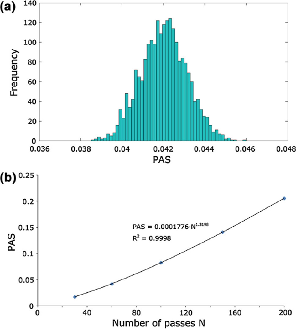
The distribution of PAS in the whole device, calculated including the contribution of τmicro, exhibited a frequency distribution comparable to a Gaussian curve when evaluated after 30, 60, 100, 150, and 200 consecutive passes of the particles. For each of these five conditions, the mean value, the standard deviation, the 10th and 90th percentiles, the kurtosis, and the skewness are summarized in Table 2. Figure 9a shows the PAS distribution after 60 passes in the device, which approximately corresponds to the typical duration of a cardio-pulmonary bypass (2 h). The power-law function c1Na used to interpolate the mean PAS values with respect to the number of passes N (Fig. 9b) provided a parameter c1 equal to 0.000189 (R2 = 0.9999).
Table 2.
Statistical variables associated to the distributions of PAS obtained after 30, 60, 100, 150 and 200 passes of the particles within the device
| 30 passes | 60 passes | 100 passes | 150 passes | 200 passes | |
|---|---|---|---|---|---|
| Mean | 0.0168 | 0.0420 | 0.0825 | 0.1407 | 0.2058 |
| Standard deviation | 0.0006 | 0.0011 | 0.0017 | 0.0023 | 0.0030 |
| 10th percentile | 0.0160 | 0.0406 | 0.0804 | 0.1378 | 0.2020 |
| 90th percentile | 0.0177 | 0.0434 | 0.0846 | 0.1438 | 0.2097 |
| Kurtosis | −0.0893 | −0.1075 | −0.0037 | 0.0847 | −0.0951 |
| Skewness | 0.1715 | 0.0224 | 0.0049 | 0.0447 | −0.069 |
The kurtosis and the skewness of a Gaussian distribution are equal to 0
Fig. 9.
a Frequency of PAS calculated after 60 passes of the platelets within the device. PAS ranges from 0 (no activation) to 1 (full activation). b Power-law interpolation of the mean PAS values with respect to the number of passes
The analysis of the ECC tubing system led to a SA distribution (Fig. 10a) with median equal to 11.81 Pa·s, 10th percentile equal to 4.59 Pa·s and 90th percentile equal to 28.27 Pa·s. The PAS distribution in the tubing system is displayed in Fig. 10b and its characteristic values are reported in Table 3 for each of the five analyzed conditions.
Fig. 10.
a Histogram of the linear stress accumulation in the ECC 3/8” tube. b Histograms of PAS measured after 60 passes of the platelets within the tubing system
Table 3.
Statistical variables associated with the distributions of PAS obtained after 30, 60, 100, 150, and 200 passes of the particles within the ECC tubing system
| 30 passes | 60 passes | 100 passes | 150 passes | 200 passes | |
|---|---|---|---|---|---|
| Mean | 0.0332 | 0.0798 | 0.1487 | 0.2506 | 0.3610 |
| Mode | 0.0089 | 0.0284 | 0.0583 | 0.1160 | 0.1625 |
| Median | 0.0128 | 0.0366 | 0.0782 | 0.1436 | 0.2188 |
| 10th percentile | 0.0083 | 0.0238 | 0.0519 | 0.0950 | 0.1473 |
| 90th percentile | 0.0422 | 0.1029 | 0.2116 | 0.4610 | 0.6794 |
| Kurtosis | 131.4 | 56.37 | 32.46 | 26.63 | 21.71 |
| Skewness | 10.76 | 6.86 | 5.23 | 4.49 | 3.82 |
The kurtosis and the skewness of a Gaussian distribution are equal to 0
4 Discussion
The aim of this work was to analyze the hemodynamic performance and the thrombogenic potential of a prototype hollow-fiber blood oxygenator with an integrated heat exchanger during ECC via CFD simulations.
In the present study, a recently developed technique for the device thrombogenicity evaluation (Xenos et al. 2010) was expanded with the introduction of a state-of-the-art mathematical model for damage accumulation (Nobili et al. 2008) to predict the platelet activation state with a full computational approach. For the first time, the thrombogenic potential of a hollow-fiber membrane oxygenator for ECC was estimated coupling an Eulerian-based CFD analysis with a Lagrangian approach for particle tracking.
From the hemodynamic point of view, the macroscale analysis allowed to determine the relative contributions to the total pressure drop of each component of the device. In particular, the presence of the integrated polymeric HE did not affect the total pressure drops significantly, as 74% of the pressure losses were located in the OXY bundle. Computed pressure drops were coherent with those obtained from the experimental tests.
Moreover, the macroscale analysis allowed identification of flow velocity patterns in different sections of the device, thus determining the risk of vortex formation and blood stagnation, which is directly related to the onset of thrombogenic phenomena at the particle level (Gartner et al. 2000). Blood stagnation areas were detected in the inlet region, thus increasing the residence time of the platelets in this area. Therefore, particles that remain trapped in the inlet section experienced significantly higher platelet activation levels than the others, even though maximum scalar stresses were found at the entrance of the outlet section, where peak turbulent kinetic energy was exhibited. In this region, the elongational components (δij = 1 in Eq. (5)) of the scalar stress were predominant over the shear stress components.
The importance of capturing the local fluid dynamics at the level of individual fibers has been clearly underlined in the literature (Dierickx et al. 2000; Hormes et al. 2011). The development of a 3D model of a subunit of the fiber bundles, coupled with a transient DPM analysis, allowed us to accurately describe the flow within the fiber bundles and to derive the distribution of the shear stresses acting on the platelets at the level of individual fibers, thus limiting the need for simplifying assumptions for the shear stress calculation. The microscale analysis highlighted the presence of non-negligible shear stresses in the fibrous regions of the HE and the OXY, that would be otherwise concealed by the porous media hypothesis (Fig. 7). Although the scalar stress values in the fibrous regions were relatively small (<1%) compared to the maximum scalar stress in the device, their impact on the total SA curve was significant because of the high residence time of the particles within the bundles (1.53 s in the HE region and 2.67 s in the OXY region).
To the best of our knowledge, despite the abundance of studies that quantitatively assessed the effect of platelet activation (i.e., thrombus formation) in ECC components (Mellgren et al. 1996;Tanaka et al. 2001), there are no studies that quantitatively assessed the mechanical factors initiating platelet activation in ECC membrane oxygenators. Gartner et al. (2000) demonstrated that low velocity regions qualitatively matched regions with a high incidence of thrombotic deposition. However, their computational analysis was limited to a 2D cross-section of the device and did not account for the microscale shear stress within the fiber bundles.
In the present study, we used the SA distributions to convey a comprehensive vision of the stress levels acting on platelets and to represent a synthetic quantitative description of the overall flow-related thrombogenic potential of the device, that is, its thrombogenic “footprint”. This approach has been previously applied to the analysis of mechanical heart valves (Alemu and Bluestein 2007; Xenos et al. 2010; Alemu et al. 2010; Morbiducci et al. 2009; Bluestein et al. 2010; Dumont et al. 2007). In these works, the SA distribution exhibited mean values of about 1–2 Pa·s, which is about one order of magnitude lower than the values found in this study. This difference arises from the fact that, while in mechanical heart valves platelets are subjected to high shear stresses deriving from their almost instantaneous passage at 1–2 m/s through small gaps (<0.2 mm), platelets in the oxygenator are subjected to both high (inlet and outlet sections) and low (fiber bundles) shear stresses, the latter being maintained for longer time intervals. On the other hand, mechanical heart valves are a life-long support implant; therefore, the risk of triggering thrombus formation should be extended to the whole life of a platelet, while the maximum duration of an ECC is about 5 h.
The SA curves were coupled with an experimentally tuned damage accumulation model that predicted the platelet activation state after multiple passes of the blood within the device. The number of the simulated passes within the device reflected the range of duration of a typical cardiopulmonary bypass (from 40 min to 4 h), assuming a priming volume of the ECC circuit equal to 2 L and the blood volume of the patient equal to 5 L.
Among the wide variety of devices used in a ECC (e.g., cannulae, pumps, filters), the oxygenator might not necessarily be the only or the most potentially thrombogenic component. In this study, we chose to evaluate the effect of the tubing system, which is always included in any ECC circuit, in order to have a fixed term of comparison for the device thrombogenicity.
The comparison between the SA and the PAS distributions calculated in the device and those calculated in the tubing system revealed that their thrombogenic potentials were comparable (Tables 2, 3). This result suggested that, despite its design complexity, the oxygenator might not be the most thrombogenic component of the ECC circuit. From this analysis, it was possible to obtain a straightforward relationship between the PAS and the number of passes in the oxygenator, which can be directly correlated with the duration of the ECC. The advantage of calculating the PAS in addition to SA was to obtain a more platelet relevant parameter that allows to determine the level of activation/damage a platelet undergoes (i.e., thrombogenic potential). It should be taken into consideration that the damage accumulation model adopted in the present study (Nobili et al. 2008) was validated experimentally over a range of shear stresses significantly lower than the maximum stresses obtained in our simulations. Moreover, a recent study by Sheriff et al. (2010) established that platelets exposed beyond a threshold of high SA are sensitized, and when exposed to subsequent low shear stresses, they activate faster than platelets not initially exposed to high SA. Therefore, particles passing through the high shear stress regions detected at the outlet section of the device might exhibit higher PAS values than those predicted by this study. Nevertheless, the power-law relationship described in this work can be considered a valid indication to easily determine the order of magnitude of PAS with respect to the duration of the ECC, as far as the contribution of the OXY/HE modules is concerned.
5 Conclusions
In this work, a computational method was proposed to quantitatively describe the thrombogenic potential of oxygenators resulting from flow-related mechanical factors (i.e., shear stresses). The method was applied to a prototype hollow-fiber membrane oxygenator with an integrated heat exchanger and compared to the tubing system of an ECC circuit. We found that the thrombogenic effects due to the shear stress in the oxygenator can be considered similar to those in other elements of an ECC circuit. We also determined a straightforward relationship between the platelet activation state in the oxygenator and the number of passes of platelets within the device. Further developments are required to investigate other possible factors affecting platelet activation (i.e., platelet-wall interaction phenomena).
Acknowledgments
The authors would like to acknowledge Sorin Group Italia, Mirandola (MO) for providing the experimental facilities required for this study and Prof. Michalis Xenos for his valuable support in the setup of the computational simulations.
Abbreviations
- BRD
Blood recirculating device
- CFD
Computational fluid dynamics
- DPM
Discrete phase modeling
- ECC
Extracorporeal circulation
- HE
Heat exchanger
- OXY
Oxygenator
- PAS
Platelet activity state
- SA
Stress accumulation;
Contributor Information
Alessandra Pelosi, Email: alessandra.pelosi@mail.polimi.it, Department of Biomedical Engineering, Politecnico di Milano, Milano, Italy.
Jawaad Sheriff, Department of Biomedical Engineering, Stony Brook University, Stony Brook, NY, USA.
Marco Stevanella, Department of Biomedical Engineering, Politecnico di Milano, Milano, Italy.
Gianfranco B. Fiore, Department of Biomedical Engineering, Politecnico di Milano, Milano, Italy
Danny Bluestein, Department of Biomedical Engineering, Stony Brook University, Stony Brook, NY, USA.
Alberto Redaelli, Department of Biomedical Engineering, Politecnico di Milano, Milano, Italy.
References
- Alemu Y, Bluestein D. Flow-induced platelet activation and damage accumulation in a mechanical heart valve: numerical studies. Artif Organs. 2007;31(9):677–688. doi: 10.1111/j.1525-1594.2007.00446.x. [DOI] [PubMed] [Google Scholar]
- Alemu Y, Girdhar G, Xenos M, Sheriff J, Jesty J, Einav S, Bluestein D. Design optimization of a mechanical heart valve for reducing valve thrombogenicity-A case study with ATS valve. ASAIO J. 2010;56(5):389–396. doi: 10.1097/MAT.0b013e3181e65bf9. [DOI] [PubMed] [Google Scholar]
- Apel J, Paul R, Klaus S, Siess T, Reul H. Assessment of hemolysis related quantities in a microaxial blood pump by computational fluid dynamics. Artif Organs. 2001;25(5):341–347. doi: 10.1046/j.1525-1594.2001.025005341.x. [DOI] [PubMed] [Google Scholar]
- Ballyk PD, Steinman DA, Ethier CR. Simulation of non-Newtonian blood flow in an end-to-side anastomosis. Biorheology. 1994;31(5):565–586. doi: 10.3233/bir-1994-31505. [DOI] [PubMed] [Google Scholar]
- Banks J, Bressloff NW. Turbulence modeling in three-dimensional stenosed arterial bifurcations. J Biomech Eng. 2007;129(1):40–50. doi: 10.1115/1.2401182. [DOI] [PubMed] [Google Scholar]
- Bird RB, Stewart WE, Lightfoot EN. Transport Phenomena. 2nd edition. New York: John Wiley; 2002. [Google Scholar]
- Bluestein D. Towards optimization of the thrombogenic potential of blood recirculating cardiovascular devices using modeling approaches. Expert Rev Med Devic. 2006;3(3):267–270. doi: 10.1586/17434440.3.3.267. [DOI] [PubMed] [Google Scholar]
- Bluestein D, Chandran KB, Manning KB. Towards non-thrombogenic performance of blood recirculating devices. Ann Biomed Eng. 2010;38(3):1236–1256. doi: 10.1007/s10439-010-9905-9. [DOI] [PMC free article] [PubMed] [Google Scholar]
- Dierickx PW, De Wachter D, Verdonck PR. Blood flow around hollow fibers. Int J Artif Organs. 2000;23(9):610–617. [PubMed] [Google Scholar]
- Dumont K, Vierendeels J, Kaminsky R, van Nooten G, Verdonck P, Bluestein D. Comparison of the hemodynamic and thrombogenic performance of two bileaflet mechanical heart valves using a CFD/FSI model. J Biomech Eng. 2007;129(4):558–565. doi: 10.1115/1.2746378. [DOI] [PubMed] [Google Scholar]
- Eloot S, De Wachter D, Van Tricht I, Verdonck P. Computational flow modeling in hollow-fiber dialyzers. Artif Organs. 2002;26(7):590–599. doi: 10.1046/j.1525-1594.2002.07081.x. [DOI] [PubMed] [Google Scholar]
- Fiore B, Soncini M, Vesentini S, Penati A, Visconti G, Redaelli A. Multi-scale analysis of the toraymyxin adsorption cartridge. Part II: computational fluid-dynamic study. Int J Artif Organs. 2006;29(2):251–260. doi: 10.1177/039139880602900211. [DOI] [PubMed] [Google Scholar]
- Fiore GB, Morbiducci U, Ponzini R, Redaelli A. Bubble tracking through computational fluid dynamics in arterial line filters for cardiopulmonary bypass. ASAIO J. 2009;55(5):438–444. doi: 10.1097/MAT.0b013e3181b3800c. [DOI] [PubMed] [Google Scholar]
- Fiore GB, Pennati G, Inzoli F, Mastrantonio F, Galavotti D. Effects of blood flow pulse frequency on mass transfer efficiency of a commercial hollow fibre oxygenator. Int J Artif Organs. 1998;21(9):535–541. [PubMed] [Google Scholar]
- Fiore GB, Redaelli A, Guadagni G, Inzoli F, Fumero R. Development of a new disposable pulsatile pump for cardiopulmonary bypass: computational fluid-dynamic design and in vitro tests. ASAIO J. 2002;48(3):260–267. doi: 10.1097/00002480-200205000-00011. [DOI] [PubMed] [Google Scholar]
- Gage KL, Gartner MJ, Burgreen GW, Wagner WR. Predicting membrane oxygenator pressure drop using computational fluid dynamics. Artif Organs. 2002;26(7):600–607. doi: 10.1046/j.1525-1594.2002.07082.x. [DOI] [PubMed] [Google Scholar]
- Gartner MJ, Wilhelm CR, Gage KL, Fabrizio MC, Wagner WR. Modeling flow effects on thrombotic deposition in a membrane oxygenator. Artif Organs. 2000;24(1):29–36. doi: 10.1046/j.1525-1594.2000.06384.x. [DOI] [PubMed] [Google Scholar]
- Goodman PD, Barlow ET, Crapo PM, Mohammad SF, Solen KA. Computational model of device-induced thrombosis and thromboembolism. Ann Biomed Eng. 2005;33(6):780–797. doi: 10.1007/s10439-005-2951-z. [DOI] [PubMed] [Google Scholar]
- Graefe R, Borchardt R, Arens J, Schlanstein P, Schmitz-Rode T, Steinseifer U. Improving oxygenator performance using computational simulation and flow field-based parameters. Artif Organs. 2010;34(11):930–936. doi: 10.1111/j.1525-1594.2010.01157.x. [DOI] [PubMed] [Google Scholar]
- Haworth WS. The development of the modern oxygenator. Ann Thorac Surg. 2003;76(6):S2216–S2219. doi: 10.1016/j.athoracsur.2003.09.012. [DOI] [PubMed] [Google Scholar]
- Hormes M, Borchardt R, Mager I, Rode TS, Behr M, Steinseifer U. A validated CFD model to predict O and CO transfer within hollow fiber membrane oxygenators. Int J Artif Organs. 2011;34(3):317–325. doi: 10.5301/ijao.2011.6494. [DOI] [PubMed] [Google Scholar]
- Idelchik IE. Handbook of Hydraulic Resistance. Boca Raton, FL: Begell House; 1994. [Google Scholar]
- Johnston BM, Johnston PR, Corney S, Kilpatrick D. Non-Newtonian blood flow in human right coronary arteries: steady state simulations. J Biomech. 2004;37(5):709–720. doi: 10.1016/j.jbiomech.2003.09.016. [DOI] [PubMed] [Google Scholar]
- Kawahito S, Maeda T, Motomura T, Takano T, Nonaka K, Linneweber J, Mikami M, Ichikawa S, Kawamura M, Glueck J, Sato K, Nose Y. Development of a new hollow fiber silicone membrane oxygenator: in vitro study. Artif Organs. 2001;25(6):494–498. doi: 10.1046/j.1525-1594.2001.06706-3.x. [DOI] [PubMed] [Google Scholar]
- Kim J, Moin P, Moser R. Turbulence statistics in fully developed channel flow at low Reynolds number. Journal of Fluid Mechanics. 1987;177:133–166. [Google Scholar]
- Legendre D, Antunes P, Bock E, Andrade A, Biscegli JF, Ortiz JP. Computational fluid dynamics investigation of a centrifugal blood pump. Artif Organs. 2008;32(4):342–348. doi: 10.1111/j.1525-1594.2008.00552.x. [DOI] [PubMed] [Google Scholar]
- Linneweber J, Chow TW, Kawamura M, Moake JL, Nose Y. In vitro comparison of blood pump induced platelet microaggregates between a centrifugal and roller pump during cardiopulmonary bypass. Int J Artif Organs. 2002;25(6):549–555. doi: 10.1177/039139880202500610. [DOI] [PubMed] [Google Scholar]
- Mellgren K, Skogby M, Jarnas A, Friberg LG, Wadenvik H, Mellgren G. Platelet activation and degradation in an experimental extracorporeal system. A comparison between a silicone membrane and a hollow-fibre oxygenator. Perfusion. 1996;11(5):383–388. doi: 10.1177/026765919601100505. [DOI] [PubMed] [Google Scholar]
- Morbiducci U, Ponzini R, Nobili M, Massai D, Montevecchi FM, Blue-stein D, Redaelli A. Blood damage safety of prosthetic heart valves. Shear-induced platelet activation and local flow dynamics: a fluid-structure interaction approach. J Biomech. 2009;42(12):1952–1960. doi: 10.1016/j.jbiomech.2009.05.014. [DOI] [PubMed] [Google Scholar]
- Mueller XM, Tevaearai HT, Augstburger M, Horisberger J, von Seges-ser LK. Experimental evaluation of the Dideco D903 Avant 1.7 hollow-fibre membrane oxygenator. Perfusion. 1998;13(5):353–359. doi: 10.1177/026765919801300512. [DOI] [PubMed] [Google Scholar]
- Niimi Y, Ichinose F, Ishiguro Y, Terui K, Uezono S, Morita S, Ya-mane S. The effects of heparin coating of oxygenator fibers on platelet adhesion and protein adsorption. Anesth Analg. 1999;89(3):573–579. doi: 10.1097/00000539-199909000-00006. [DOI] [PubMed] [Google Scholar]
- Nobili M, Sheriff J, Morbiducci U, Redaelli A, Bluestein D. Platelet activation due to hemodynamic shear stresses: damage accumulation model and comparison to in vitro measurements. ASAIO J. 2008;54(1):64–72. doi: 10.1097/MAT.0b013e31815d6898. [DOI] [PMC free article] [PubMed] [Google Scholar]
- Pappalardo F, Della Valle P, Crescenzi G, Corno C, Franco A, Torracca L, Alfieri O, Galli L, Zangrillo A, D’Angelo A. Phosphorylcholine coating may limit thrombin formation during high-risk cardiac surgery: a randomized controlled trial. Ann Thorac Surg. 2006;81(3):886–891. doi: 10.1016/j.athoracsur.2005.09.006. [DOI] [PubMed] [Google Scholar]
- Ramstack JM, Zuckerman L, Mockros LF. Shear-induced activation of platelets. J Biomech. 1979;12(2):113–125. doi: 10.1016/0021-9290(79)90150-7. [DOI] [PubMed] [Google Scholar]
- Schaadt J. Oxygenator thrombosis: an international phenomenon. Perfusion. 1999;14(6):425–435. doi: 10.1177/026765919901400605. [DOI] [PubMed] [Google Scholar]
- Sheriff J, Bluestein D, Girdhar G, Jesty J. High-shear stress sensitizes platelets to subsequent low-shear conditions. Ann Biomed Eng. 2010;38(4):1442–1450. doi: 10.1007/s10439-010-9936-2. [DOI] [PMC free article] [PubMed] [Google Scholar]
- Swartz MA, Fleury ME. Interstitial flow and its effects in soft tissues. Annu Rev Biomed Eng. 2007;9:229–256. doi: 10.1146/annurev.bioeng.9.060906.151850. [DOI] [PubMed] [Google Scholar]
- Tanaka M, Kawahito K, Adachi H, Isawa H, Ino T. Platelet damage caused by the centrifugal pump: laser-light scattering analysis of aggregation patterns. Artif Organs. 2001;25(9):719–723. doi: 10.1046/j.1525-1594.2001.06863.x. [DOI] [PubMed] [Google Scholar]
- Varghese SS, Frankel SH. Numerical modeling of pulsatile turbulent flow in stenotic vessels. J Biomech Eng. 2003;125(4):445–460. doi: 10.1115/1.1589774. [DOI] [PubMed] [Google Scholar]
- Verdonck P. The role of computational fluid dynamics for artificial organ design. Artif Organs. 2002;26(7):569–570. doi: 10.1046/j.1525-1594.2002.00920.x. [DOI] [PubMed] [Google Scholar]
- Vesentini S, Soncini M, Zaupa A, Silvestri V, Fiore GB, Redaelli A. Multi-scale analysis of the toraymyxin adsorption cartridge. Part I: molecular interaction of polymyxin B with endotoxins. Int J Artif Organs. 2006;29(2):239–250. doi: 10.1177/039139880602900210. [DOI] [PubMed] [Google Scholar]
- Xenos M, Girdhar G, Alemu Y, Jesty J, Slepian M, Einav S, Bluestein D. Device Thrombogenicity Emulator (DTE)-design optimization methodology for cardiovascular devices: a study in two bileaflet MHV designs. J Biomech. 2010;43(12):2400–2409. doi: 10.1016/j.jbiomech.2010.04.020. [DOI] [PMC free article] [PubMed] [Google Scholar]
- Yamaguchi T, Ishikawa T, Imai Y, Matsuki N, Xenos M, Deng Y, Bluestein D. Particle-based methods for multiscale modeling of blood flow in the circulation and in devices: challenges and future directions. Sixth International Bio-Fluid Mechanics Symposium and Workshop March 28–30, 2008 Pasadena, California. Ann Biomed Eng. 2010;38(3):1225–1235. doi: 10.1007/s10439-010-9904-x. [DOI] [PMC free article] [PubMed] [Google Scholar]
- Zimmermann AK, Weber N, Aebert H, Ziemer G, Wendel HP. Effect of biopassive and bioactive surface-coatings on the hemocompatibility of membrane oxygenators. J Biomed Mater Res B Appl Biomater. 2007;80(2):433–439. doi: 10.1002/jbm.b.30614. [DOI] [PubMed] [Google Scholar]


