Abstract
We propose a kind of anisotropic gradient-index (GRIN) metamaterials, which can be used to control differently-polarized waves independently. We show that two three- dimensional (3D) planar lenses made of such anisotropic GRIN metamaterials are able to make arbitrary beam deflections for the vertical (or horizontal) polarization but have no response to the horizontal (or vertical) polarization. Then the vertically- and horizontally-polarized waves are separated and controlled independently to deflect to arbitrarily different directions by designing the anisotropic GRIN planar lenses. We make experimental verifications of the lenses using such a special metamaterial, which has both electric and magnetic responses simultaneously to reach approximately equal permittivity and permeability. Hence excellent impedance matching is obtained between the GRIN planar lenses and the air. The measurement results demonstrate good performance on the independent controls of differently-polarized waves, as observed in the numerical simulations.
The control of differently-polarized waves is very important in both the optical and the microwave regimes. One typical application is the polarization beam splitter (PBS), which serves to split orthogonally-polarized beams/waves into different directions. Traditionally, PBSs are realized using natural crystal birefringence or artificial anisotropic multi-layered dielectrics1,2, which are sensitive to the incident angle. Furthermore, the traditional PBSs are usually made electrically thick in order to obtain enough splitting angle. Recently, PBSs have also been achieved using two-dimensional (2D) photonic crystals and metamaterials3,4,5,6,7,8 based on the theory of transformation optics9,10 or the idea that media with negative and positive refractions are able to split waves with orthogonal polarizations, respectively. However, the complicated materials derived by these schemes are essentially difficult to possess low loss and broadband properties even if they can be fabricated with resonant metamaterial designs and technologies.
Gradient-index (GRIN) metamaterials whose refractive indices change gradually according to the geometry of devices, however, have better performance with low loss and broadband and are easier to be designed and fabricated because they do not work at the resonance frequencies. A lot of exciting devices based on GRIN metamaterials have been proposed and realized to modulate the propagation of electromagnetic waves, such as the carpet (or ground-plane) cloaks in both two and three dimensions10,11,12,13,14,15,16,17,18,19, the planar lenses20,21, the traditional Luneburg and Maxwell fisheye lenses22, and the flattened Luneburg lenses23,24. However, the currently available GRIN metamaterials are all isotropic, which limits the ability to control the electromagnetic waves, especially to control differently-polarized waves. Compared to the isotropic metamaterials, the anisotropic metamaterias have much stronger ability to control the electromagnetic waves25,26,27, but most of them are achieved by using resonant structures with large loss and narrow working band. When the extremely-anisotropic effective parameters are not required, the non-resonant anisotropic metamaterials have advantages of low loss and broad working band, which have been applied in designing the d. c. magnetic metamaterials28 and the GRIN metamaterials in two-dimensional space29.
In this work, we propose a kind of anisotropic GRIN metamaterial to control the propagations of two orthogonally-polarized electromagnetic waves independently. The anisotropic property makes GRIN metamaterial slabs have different responses to the horizontal and vertical polarizations, and the gradient-index property makes the horizontal or vertical polarization have a deflecting angle when passing through the metamaterial slabs. Here, we propose three-dimensional (3D) PBSs composed of two anisotropic and gradient-index slabs, one of which is designed to only have response to the horizontal polarized waves but no response to the vertical polarized waves, and the other is designed to only have response to the vertical polarized waves but no response to the horizontal polarized waves. Hence, if we use the spherical coordinate system of (r, θ, φ) in the paper, the proposed PBSs have ability to split two orthogonal polarizations and make each of them deflect to different directions of (θ1, φ1) and (θ2, φ2) independently. A special unit cell of metamaterials with both electric and magnetic responses is chosen to construct the PBSs, and hence the anisotropic GRIN slabs have good impedance matching to the free space. Finally, the metamaterial PBSs are designed, fabricated and measured, which show excellent agreements to the numerical simulations.
Results
Theory and design
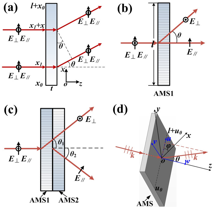
According to the geometrical optics, the plane waves can be made a deflection by passing through an isotropic GRIN planar lens, as shown in Fig. 1(a). We suppose that the refractive index of the lens is gradually changed along the x direction and two incident rays are normal to the slab with the thickness of t at the locations of x = x1 and x = x1 + δx, whose refractive indices are n(x1) and n(δx + x1), respectively. In GRIN planar lens, we assume that the rays approximately propagate along a straight line in +z direction. Then, the rays will have different phase shifts when passing through the slab and make a deflection with the angle of θ, and their phase relationship can be written as30:
 |
When δx → 0, then the Eq. (1) is reduced to
 |
By solving above differential equation, the relation between the deflecting angle of θ and refractive-index distributions of the lens is derived as:
 |
in which n0 is the refractive index at the location of x = x0, which is a positive constant to make sure n(x) > 0, and l and t are the side length and thickness of the lens, respectively.
Figure 1. The schematic of the proposed 3D PBSs.
(a) The waves deflected by passing through an isotropic GRIN planar lens, in which the vertical and horizontal polarizations cannot be separated. (b) The side view (xoz) of a3D PBS made of a single slab AMS1, in which only the vertical polarization is deflected to the angle of θ. (c) The side view (xoz) of a 3D PBS made of two slabs AMS1 and AMS2, in which both vertical and horizontal polarizations are deflected to angles of θ1 and θ2 independently. (d) The 3D view of the PBS, in which the vertical/horizontal polarization is deflected to a spatial direction of (θ, φ) by passing through the PBS.
In order to control two orthogonal polarizations independently, we propose and design anisotropic GRIN lens, whose permittivity and permeability are defined as:
 |
According to the Maxwell Equations, the relationship between the E, H and k can be written as
 |
 |
in which k is the vector of the propagation number. We suppose that the incident plane waves propagate along the +z direction, and the x and y polarizations of electric field correspond to the horizontal and vertical polarizations, respectively. In GRIN planar lens, we also assume that the waves approximately propagate along a straight line in +z direction, and then we have kx ≈ 0, ky ≈ 0, Ez ≈ 0 and Hz ≈ 0. Then Eqs. (5) and (6) can be reduced as:
 |
 |
From Eqs. (7) and (8), two transmission modes of kz can be obtained:
 |
 |
in which n⊥ and n|| are the refractive indices corresponding to vertically (y) and horizontally (x) polarized waves, respectively.
The sketches (side view) of the proposed GRIN PBSs are demonstrated in Figs. 1(b) and (c), in which the anisotropic GRIN Metamaterial Slab 1 (AMS1 in Fig. 1(b)) is designed to only have response to the vertical polarization, but no response to the horizontal polarization. We also suppose that the refractive index of the AMS1 is gradually changed along the x direction:
 |
 |
in which n(x) is expressed as Eq. (3). Hence, only the vertical polarizations will be deflected by passing through AMS1, but the horizontal polarizations will not be affected. Similarly, the anisotropic GRIN Metamaterial Slab 2 (AMS2) is designed to only have response to the horizontal polarization, but no response to the vertical polarization:
 |
 |
By combining AMS1 and AMS2 together, the deflection of vertical and horizontal polarizations can be controlled by AMS1 and AMS2 independently, and arbitrarily splitting angle between two polarizations can be achieved, as demonstrated in Fig. 1(c).
The 3D view of a square AMS is illustrated in Fig. 1(d). We define a new local coordinate system uvw, in which the w axis coincides with the z axis in the original coordinate system, and the u axis rotates an angle of φ with respect to the x axis in the xoy plane. Here, we suppose that all incident plane waves are propagating along the z (or w) axis, and the x- and y- polarizations are corresponding to the horizontal and vertical polarizations, respectively. If the permittivity and permeability of AMS1 are designed as ε1y(u) = μ1x(u) = n0 + ((u − u0)sinθ1)/t, (u0 < u < l + u0) and ε1x(u) = μ1y(u) = 1 under the local uvw coordinate, then the refractive indices are n1⊥ = n1y = ε1y(u) = μ1x(u) and n1|| = n1x = 1, and the characteristic impedance of the propagating wave is ηz = 1, which is matched to the free space. Hence the deflecting beam of the vertical polarization will be directed to (θ1, φ1), in which φ1 is the angle between the x and u axes. Similarly, if the permittivity and permeability of AMS2 are given as ε2x(u) = μ2y(u) = n0 + ((u − u0)sinθ2)/t, (u0 < u < l + u0), and the angle between the x and u axes is φ2, then the deflecting beam of the horizontal polarization is directed to (θ2, φ2). As a consequence, when AMS1 and AMS2 are cascaded together (see Fig. 1(c)), the two orthogonal polarizations can be separated and propagating to two arbitrary directions, and the deflecting angles of the horizontally- and vertically-polarized waves can be independently controlled in the 3D space.
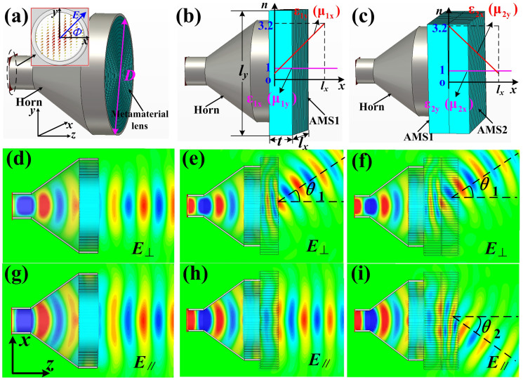
Based on the above theoretical analysis, two special cases for (θ1 = 30°, φ1 = 0) and (θ2 = 30°, φ2 = 180°) have been simulated by using commercial software, the CST Microwave Studio, and the simulation results are illustrated in Fig. 2. The simulated PBS is composed of a metamaterial lens antenna that was realized earlier21 and the AMS1 and AMS2 lenses, as shown in Figs. 2(a–c). The metamaterial lens antenna can transform quasi-spherical waves into plane waves quickly according to Ref. [21], which can be served as the polarized incident plane waves, and the diameter of antenna's aperture is D = 100 mm. The electric-field vector at the input port is set as linear polarization with an angle Φ = 45° to the x axis as shown in Fig. 2(a), so that both vertical and horizontal polarizations can be achieved by decomposing the total electric-field vector. Fig. 2(a) is a model of metamaterial lens antenna21, whose simulated near electric-field distributions of both vertical and horizontal polarizations are illustrated in Figs. 2(d) and (g), respectively. The results show that both polarizations are mixed together propagating along the +z direction with θ = 0 and φ = 0. Fig. 2(b) is a model of metamaterial lens antenna plus AMS1 with θ1 = 30° and φ1 = 0, and the permittivity and permeability tensors of AMS1 are given according to Eqs. (11) and (12) with ε1y (μ1x) linearly increased and ε1x (μ1y) unchanged along +x direction, in which the dimensions of the AMS1 are lx × ly × t = 128 × 128 × 25.6 mm3. The simulated electric-field distributions of both polarizations are given in Figs. 2(e) and (h). We observe that the vertically-polarized waves are deflected to the +x direction by passing through AMS1, while the horizontally-polarized waves are still propagating along the +z direction without any deflection. Hence the splitting angle between two polarizations is 30°. Figure 2(c) is a model of metamaterial lens antenna plus AMS1 with (θ1 = 30°, φ1 = 0) and AMS2 with (θ2 = 30°, φ2 = 180°), and the permittivity and permeability tensors of AMS2 are given according to Eqs. (13) and (14) with ε1x (μ1y) linearly decreased and ε1y (μ1x) unchanged along +x direction, in which the dimensions of the AMS2 are also lx × ly × t = 128 × 128 × 25.6 mm3. The simulated electric-field distributions of both polarizations are demonstrated in Figs. 2(f) and (i). In this case, we observe that the vertical polarization is deflected to the +x direction by passing through AMS1, while the horizontal polarization is deflected to the −x direction by passing through AMS2. Hence we achieve a large splitting angle 60° between two polarizations.
Figure 2.
The simulation models of PBSs (a,b,c) including variations of permittivity and permeability tensors for AMS1 (b) and AMS2 (c) and their near electric-field distributions for vertical polarizations (d,e,f) and horizontal polarizations (g,h,i) at 10 GHz. (a,d,g) The metamaterial lens antenna (isotropic GRIN lens), in which D = 100 mm and Φ = 45°. (b,e,h) The metamaterial lens antenna plus AMS1, in which lx = ly = 128 mm, t = 25.6 mm and θ1 = 30°. (c,f,i) The metamaterial lens antenna plus AMS1 and AMS2, in which θ1 = 30° and θ2 = 30°.
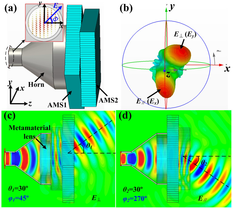
A more general case for (θ1 = 30°, φ1 = 45°) and (θ2 = 30°, φ2 = 270°) have also been simulated for further demonstration. The model of PBS is shown in Fig. 3(a), in which AMS1 and AMS2 are placed on front of the metamaterial horn antenna with θ1 = 30° and φ1 = 45° for AMS1 θ2 = 30° and φ2 = 270° for AMS2, respectively. Figure 3(b) demonstrates the far-field pattern of PBS at 10 GHz, from which we observe that the incident waves are split into two different directions with (θ1 = 30°, φ1 = 45°) for the vertical polarization (E⊥) and (θ2 = 30°, φ2 = 270°) for the horizontal polarization (E∥). Figures 3(c) and (d) are the near electric field distributions of both vertical and horizontal polarizations by passing through the PBS, which clearly show that the vertical polarization is only tuned by AMS1 to be deflected to (θ1 = 30°, φ1 = 45°) and the horizontal polarization is only tuned by AMS2 to the spatial direction (θ2 = 30°, φ2 = 270°), exactly as pre-designed.
Figure 3. The simulation results of the proposed 3D PBS.
(a) The simulation model, in which Φ = 45°. (b) The simulated far-field pattern with the vertical polarization deflecting to (θ1 = 30°, φ1 = 45°) and the horizontal polarization deflecting to (θ2 = 30°, φ2 = 270°). (c) The simulated near electric-field distribution of the vertical polarization deflecting to θ1 = 30° on the plane of φ1 = 45°. (d) The simulated near electric-field distribution of the horizontal polarization deflecting to θ2 = 30° on the plane of φ2 = 270°.
Experimental results
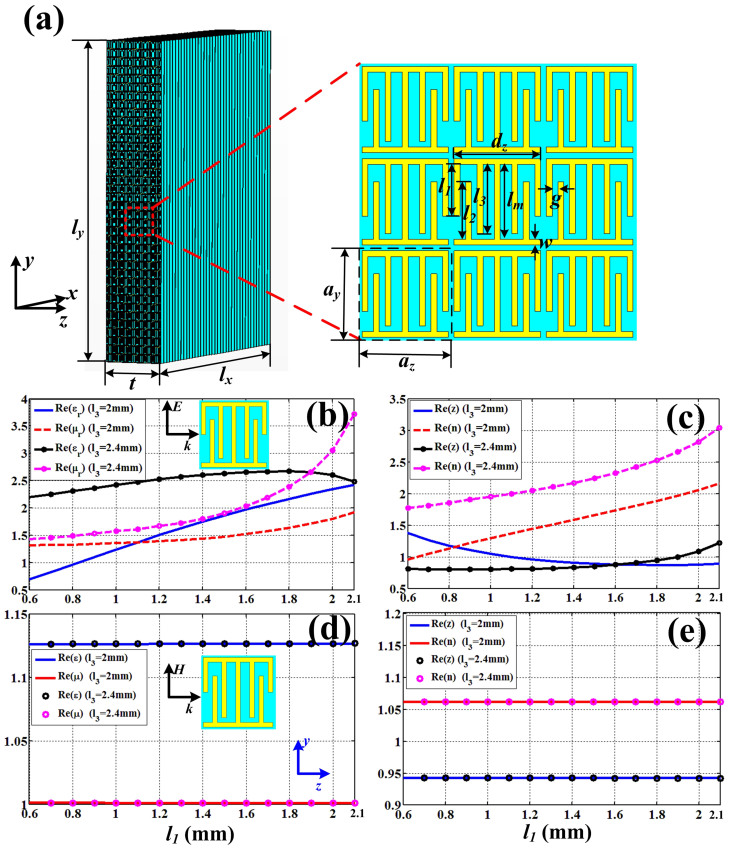
In order to verify the control of differently polarized waves experimentally, we first design and fabricate the anisotropic GRIN lenses. Figure 4(a) shows a model of AMS1 with φ1 = 0, which is constructed by a special anisotropic GRIN metamaterial. The unit cell is specially designed (see Fig. 4(a)) to achieve the electric and magnetic responses simultaneously, in which the dimensions are optimized as ay = 3.2 mm, az = 3.2 mm, dz = 3 mm, lm = 2.6 mm, l3 = 2.4 mm, w = 0.2 mm, and g = 0.2 mm. The other two parameters l1 and l2 can be tuned to make gradient indexes of refraction. The anisotropic GRIN metamaterials are fabricated on printed circuit board (PCB) of F4B with the thickness 0.5 mm, relative permittivity 2.65, and loss tangent 0.001. The anisotropic GRIN slab is assembled by 40 pieces of metamaterial slices with interval 3.2 mm (see Fig. 4(a)), in which the overall slab size is lx = ly = 128 mm and thickness is t = 25.6 mm. In experiment, we chose the unit cells with l2 = 2 mm and l1 varied from 0.6 mm to 2.0 mm to realize discrete indices of refraction from 0.9 to 2.1 and l2 = 2.4 mm and l1 varied from 1.3 mm to 2.2 mm to realize discrete indices of refraction from 2.15 to 3, respectively.
Figure 4. An anisotropic GRIN lens constructed by a special metamaterial and the effective parameters of metamaterial unit cells at 10 GHz.
(a) The lens with φ1 = 0 and dimensions of the unit cell. (b) The effective permittivity and permeability for electric-field vector polarized along the y axis. (c) The effectively refractive index and impedance for electric-field vector polarized along the y axis. (d) The effective permittivity and permeability for electric-field vector polarized along the x axis. (e) The effectively refractive index and impedance for electric-field vector polarized along the x axis.
To investigate the responses of metamaterial unit cell, we have retrieved the effective material parameters, as shown in Figs. 4(b)–(e). First we consider the polarization when the incident electric-field vector is along the y axis and the magnetic-field vector along the x axis. By fixing l2 as 2 mm and l1 varying from 0.6 to 2.1 mm, the relative permittivity (εr) increases from 1.3 to 2.4, and the relative permeability (μr) increases from 1.3 to 1.9, as the blue solid line and the red dashed line shown in Fig. 4(b). In the meantime, the effective impedance (z) decreases from 1.3 to 0.8, which has good matching to the wave impedance in the free space, while the refractive index (n) increases gradually from 0.9 to 2.2, as the blue solid line and the red dashed line shown in Fig. 4(c). Similarly, when l2 is fixed as 2.4 mm and l1 varies from 0.6 to 2.1 mm, εr increases from 2.2 to 2.7 and μr increases from 1.4 to 3.7 (see the black solid line and the pink dashed line in Fig. 4(b)), while the impedance z increases from 0.8 to 1.2 and n increases from 1.8 to 3 (see the black solid line and the pink dashed line in Fig. 4(c)). Hence, the index of refraction can be designed from 0.9 to 3, and the impedance is kept around one to match with the free space. Next, we consider the other polarization when the incident electric-field vector is along the x axis and the magnetic-field vector along the y axis, as illustrated in Figs. 4(d) and 4(e). In such a polarization, however, the effective εr equals 1.13 and μr equals 1 as l1 varies from 0.6 to 2.1 mm, no matter l2 = 2 mm or 2.4 mm. Correspondingly, the index of refraction is 1.06 and the impedance is 0.94, as shown in Fig. 4(e). Hence, the unit cell has nearly no response to this polarization. In this way, we have successfully designed the artificially anisotropic GRIN planar lens.
From above discussions, if the electric-field vector is polarized along the y axis, the incident wave will be deflected by passing through the slab shown in Fig. 4(a), in which the deflection angle is determined from Eq. (3). However, if the electric-field vector is polarized along the x axis, the incident wave will pass through the slab without any deflections. Hence, the vertically polarized wave will be deflected and the horizontally polarized wave is not influenced by passing through AMS1. In general, if AMS1 and AMS2 are properly designed and combined together (see Fig. 1(c)), then the two orthogonally polarized waves will be separated to different directions, which are controlled by AMS1 and AMS2 independently.
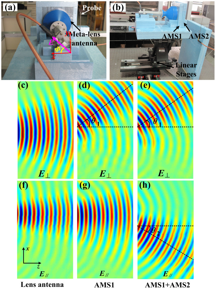
For the convenience of experiments, we design, fabricate, and measure a 3D PBS, which is made of AMS1 with (θ1 = 30°, φ1 = 0) and AMS2 with (θ2 = 30°, φ2 = 180°). The experimental set up and measured results of the proposed PBS are presented in Figs. 5(a) and (b). Consistent with the numerical simulations, the planar metamaterial lens antenna21 is used to generate the linear-polarized plane waves, in which the electric-field vector is set as Φ = 45° (see Fig. 6(a)), so the total electric field can be decomposed to Ex (or E∥) and Ey (or E⊥). The fabricated sample is placed on a linear stage, and a probe is fixed on front of AMS1, as shown in Fig. 5(b). Then the near electric fields of different polarizations can be measured by moving the sample in the xoz plane. We remark that all the sky-blue materials in Fig. 5 are foam, which has the similar property to the air, and hence will not affect the experiments.
Figure 5. The experimental setup of the proposed PBSs and measured near electric-field distributions at 10 GHz.
(a) The back view of the experimental setup, in which an isotropic GRIN planar lens antenna is used as the excitation with the electric-field polarization of Φ = 45°. (b) The side view of the experimental setup, in which the fabricated sample is placed on the top of a linear stage. (c–e) The measured near electric fields for the vertical polarizations of the planar metamaterial antenna, AMS1, and AMS1 plus AMS2, in which θ1 = 30°. (f–h) The measured near electric fields for the horizontal polarizations of the planar metamaterial antenna, AMS1, and AMS1 plus AMS2, in which θ1 = θ2 = 30°.
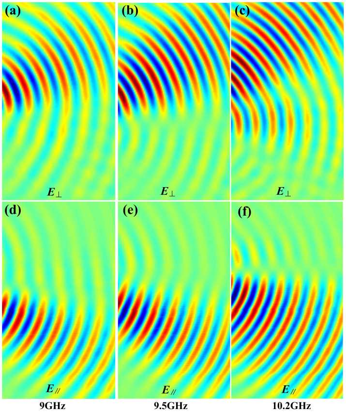
Figure 6. The measured near electric-field distributions at different frequencies of the PBS with AMS1 and AMS2.
(a–c) The vertical polarizations at 9 GHz, 9.5 GHz, and 10.2 GHz. (d–f) The horizontal polarizations at 9 GHz, 9.5 GHz, and 10.2 GHz.
The measured results of near electric fields at 10 GHz are illustrated in Figs. 5(c–h), in which Figs. 5(c) and (f) show the measured electric fields of the vertical and horizontal polarizations generated by the metamaterial lens antenna respectively21. We clearly notice that both polarizations are propagating along the x axis without splitting. Figures 5(d) and (g) illustrate the measured electric fields of vertical and horizontal polarizations when only AMS1 is placed on front of the lens antenna. We observe that the vertically polarized waves are deflected to the +x direction by passing through AMS1 with the deflection angle θ1 = 30° (Fig. 5(d)), while the horizontally polarized waves are still propagating along the +z direction without any deflection (Fig. 5(g)). We should remark that the near electric fields generated by the metamaterial lens antenna is not strict plane waves, whose wave fronts become wider and wider when the waves propagates farther and farther away from the lens antenna. Hence, the wave beams shown in Fig. 5(g) seem much wider than those in Fig. 5(f) because the receiving probe was placed farther away from the lens antenna for measuring the near electric-field distributions of AMS1 plus the lens antenna (Figs. 5(d) and (g)) than that of only lens antenna (Figs. 5(c) and (f)). When both AMS1 and AMS2 are placed on front of the lens antenna, the measured electric fields for the vertical and horizontal polarizations are demonstrated in Figs. 5(f) and (h), respectively, which clearly show that the vertically polarized waves are deflected to the +x direction and the horizontally polarized waves to the −x direction with deflecting angles of θ1 = θ2 = 30°. Hence, the observed splitting angle between such two polarizations is θ1 + θ2 = 60°. Comparing Fig. 5 with Fig. 2, all measurement results have very good agreements to the numerical simulations.
The proposed anisotropic GRIN metamaterial, planar lens and PBS have relatively large bandwidth. Figure 6 illustrates the measured PBS results of near electric fields in the frequency range from 9 to 10.2 GHz, in which Figs. 6(a)–(c) give the vertically polarized waves deflecting to the +x direction and Figs. 6(d)–(f) show the horizontally polarized waves deflecting to the −x direction. From the measurement results, we obtain good polarization splitting performance in a wide frequency band, and the absolute bandwidth reaches 1 GHz.
Conclusion
In this work, we have proposed a kind of anisotropic GRIN metamaterial, which differs from the widely investigated homogeneous anisotropic metamaterials that can convert the polarization status. The proposed anisotropic GRIN metamaterial has much stronger ability to control the electromagnetic waves, such as the control of differently polarized waves independently. In details, two anisotropic metamaterial slab lenses of AMS1 and AMS2 have been designed and fabricated to split and control the propagations of vertically and horizontally polarized waves. We have also presented a specially-designed anisotropic metamaterial unit cell which has both electric and magnetic responses simultaneously to make good impedance match to the free space. In a relatively wide frequency band, the experimental results showed very good controlling performance.
Methods
In the experiment, a linear-polarized plane wave is required as the excitation, hence a metamaterial planar lens antenna is used, which can transform quasi-spherical waves into be the plane waves21. A gradient-index metamaterial lens, whose distribution of refractive index satisfies the readial gradient index function, is placed inside the apterture of a circular horn fed by a rectagular waveguide as shown in Figs. 5(a) and (b). Hence the qusi-spherical wave fronts generated by the circular horn will be transfromed to planar wave fronts when passing through the gradient metamaterial lens, which has ability to modulate the phases of waves to be uniform on the aperture of the lens antenna. Meanwhile, the metamaterial antenna should be put behind the PBS with an angle of Φ = 45° between the electric-field vector and x axis as shown in Fig. 5, so that the total electric-field vector can be decomposed to be two orthogonal linear polarizations, i. e. the vertical (Ex) and the horizontal (Ey) polarizations. The PBSs of AMS1 and AMS2 are placed in front of metamaterial lens to control the deflection of vertical and horizontal polarizations, respectively. In the experiment, the detecting probe was fixed, and the experimental sample was controlled by an electronic motor that moves automatically to measure the near fields continuously, as shown in Fig. 5(b). We remark that the detection probe should be fixed parallel to the y axis to get the vertical polarized electric-field distributions and fixed parallel to the x axis to get the horizontal polarized electric-field distributions. The measured near-field distributions for different polarizations show good controlling performance of the designed anisotropic gradient-index metamaterials.
Author Contributions
H.F.M. designed, performed and interpreted the experiments. G.Z.W. generated numerical simulations. W.X.J. made theoretical analysis. T.J.C. supervised and interpreted the design and experiments, and wrote the manuscript.
Acknowledgments
This work was supported in part by the National Science Foundation of China under Grant Nos. 61138001, 61171024 and 61171026, in part by the National High Tech (863) Projects under Grant Nos. 2011AA010202 and 2012AA030402, and in part by the 111 Project under Grant No. 111-2-05, and in part by the Fundamental Research Funds for Central Universities under No. 3204003101.
References
- Shiraishi K., Sato T. & lawakami S. Experimental verification of a form-birefringent polarization splitter. Appl. Phys. Lett. 58, 211–212 (1991). [Google Scholar]
- Sato T., Shiraishi K., Tsuchida K. & lawakami S. Laminated polarization splitter with a large split angle. Appl. Phys. Lett. 61, 2633–2634 (1992). [Google Scholar]
- Zhao J., Chen Y. & Feng Y. Polarization beam splitting through an anisotropic metamaterial slab realized by a layered metal-dielectric structure. Appl. Phys. Lett. 92, 071117 (2008). [Google Scholar]
- Kwon D. & Werner D. H. Polarization splitter and polarization rotator designs based on transformationoptics. Opt. Express 16, 18731–18738 (2008). [DOI] [PubMed] [Google Scholar]
- Luo H., Ren Z., Shu W. & Li F. Construct a polarizing beam splitter by an anisotropic metamaterial slab. Appl. Phys. B 87, 283–287 (2007). [Google Scholar]
- Ao X., Liu L., Wosinski L. & He S. Polarization beam splitter based on a two-dimensional photonic crystal of pillar type. Appl. Phys. Lett. 89, 171115 (2006). [Google Scholar]
- Mocella V., Dardano P., Moretti L. & Rendina I. A polarizing beam splitter using negative refraction of photonic crystals. Opt. Express 13, 7699–7707 (2005). [DOI] [PubMed] [Google Scholar]
- Shen Y. et al. A tunable power splitter based on modes coupling and self-collimation effect in two-dimensional photonic crystals. Opt. Commun. 285, 2846–2850 (2012). [Google Scholar]
- Pendry J. B., Schurig D. & Smith D. R. Controlling electromagnetic fields. Science 312, 1780–1783 (2006). [DOI] [PubMed] [Google Scholar]
- Leonhardt U. Optical conformal mapping. Science 312, 1777–1780 (2006). [DOI] [PubMed] [Google Scholar]
- Li J. & Pendry J. B. Hiding under the Carpet: A New Strategy for Cloaking. Phys. Rev. Lett. 101, 203901 (2008). [DOI] [PubMed] [Google Scholar]
- Liu R. et al. Broadband ground-plane cloak. Science 323, 366–369 (2009). [DOI] [PubMed] [Google Scholar]
- Valentine J., Li J., Zentgraf T., Bartal G. & Zhang X. An optical cloak made of dielectrics. Nat. Mater. 8, 568–571 (2009). [DOI] [PubMed] [Google Scholar]
- Gabrielli L. H., Cardenas J., Poitras C. B. & Lipson M. Silicon nanostructure cloak operating at optical frequencies. Nat. Photon. 3, 461–463 (2009). [Google Scholar]
- Ma H. F., Jiang W. X., Yang X. M., Zhou X. Y. & Cui T. J. Compact-sized and broadband carpet cloak and free-space cloak. Opt. Express 17, 19947–19959 (2009). [DOI] [PubMed] [Google Scholar]
- Ergin T., Stenger N., Brenner P., Pendry J. B. & Wegener M. Three-dimensional invisibility cloak at optical wavelengths. Science 328, 337–339 (2010). [DOI] [PubMed] [Google Scholar]
- Ma H. F. & Cui T. J. Three-dimensional broadband ground-plane cloak made of metamaterials. Nat. Commun. 1, 21 (2010). [DOI] [PMC free article] [PubMed] [Google Scholar]
- Zhang B., Chan T. & Wu B. Lateral shift makes a ground-plane cloak detectable. Phys. Rev. Lett. 104, 233903 (2010). [DOI] [PubMed] [Google Scholar]
- Chen X. et al. macroscopic invisibility cloaking of visible light. Nat. Commun. 2, 176 (2011). [DOI] [PMC free article] [PubMed] [Google Scholar]
- Ma H. F. et al. Experiments on high-performance beam-scanning antennas made of gradient-index metamaterials. Appl. Phys. Lett. 95, 194107 (2009). [Google Scholar]
- Chen X., Ma H. F., Zou X. Y., Jiang W. X. & Cui T. J. Three-dimensional broadband and high-directivity lens antenna made of metamaterials. J. Appl. Phys. 110, 044904 (2011). [Google Scholar]
- Ma H. F. et al. Three-dimensional gradient-index materials and their applications in microwave lens antennas. IEEE Trans. Antennas Propag. 61, 2561–2568 (2013). [Google Scholar]
- Kundtz N. & Smith D. R. Extreme-angle broadband metamaterial lens. Nat. Mater. 9, 129–132 (2010). [DOI] [PubMed] [Google Scholar]
- Ma H. F. & Cui T. J. Three-dimensional broadband and broad-angle transformation-optics lens. Nat. Commun. 1, 124 (2010). [DOI] [PubMed] [Google Scholar]
- Schurig D. et al. Metamaterial electromagnetic cloak at microwave frequencies. Science 314, 977–980 (2006). [DOI] [PubMed] [Google Scholar]
- Jiang W. X. & Cui T. J. Radar illusion via metamaterials. Phys. Rev. E 83, 026601 (2011). [DOI] [PubMed] [Google Scholar]
- Jiang W. X. & Cui T. J. Shrinking an arbitrary object as one desires using metamaterials. Appl. Phys. Lett. 98, 204101 (2011). [Google Scholar]
- Magnus F. et al. A d. c. magnetic metamaterial. Nat. Mater. 7, 295 (2008). [DOI] [PubMed] [Google Scholar]
- Liu R. et al. Broadband gradient index microwave quasi-optical elements based on non-resonant metamaterials. Opt. Express 17, 21030 (2009). [DOI] [PubMed] [Google Scholar]
- Smith D. R., Mock J. J., Starr A. F. & Schurig D. Gradient index metamaterials. Phys. Rev. E 71, 036609 (2005). [DOI] [PubMed] [Google Scholar]


