Abstract
We report the effect of the probe location and wavelength on the emission spatial distribution and spectral properties of fluorophores located on structures which display Tamm states. Our structure consists of a one-dimensional photonic crystal (1DPC)—that is, a multilayer structure of alternate high and low refractive index dielectrics—and a thin top silver film. Simulations show the presence of Tamm and surface plasmon modes in the structure. The electric field intensities for the Tamm modes are located mostly in the dielectric layer below the metal film. The corresponding field intensities for the surface plamon modes are located above the metal film in the distal side. Tamm states can be in resonance with the incident light normal or near normal to the surface, within the light line, and can be accessed without the use of a coupling prism or gratings. We investigated the emission spectra and angular distribution of the emission for probes located above and below the metal film to explore the interaction of fluorophores with Tamm plasmons and surface plasmons modes. Three probes were chosen with different overlap of the emission spectra with the Tamm modes. The fluorophores below the metal film coupled predominantly with the Tamm state and displayed more intense and only Tamm state-coupled emission (TSCE). Probes above the metal film display both surface plasmon-coupled emission (SPCE) and Tamm state-coupled emission. In contrast to SPCE, which shows only KR, P-polarized emission, the Tamm states can display both S- and P-polarized emission and can be populated using both RK and KR illuminations. The TSCE angle is highly sensitive to wavelength, which suggests the use of Tamm structures to provide both directional emission and wavelength dispersion. The combination of plasmonic and photonic structures with directional emission close to surface normal offers the opportunities for new design formats for clinical testing, portable devices, and other fluorescence-based applications.
Introduction
Fluorescence spectroscopy is a widely used technique in the chemical and biosciences due to its high sensitivity, rapid response, and versatile instrumentation. Accordingly, it has found applications in the biosciences including imaging, sensing, sequencing, and medical diagnostics. These applications have driven the development of fluorescence technology in numerous directions such as probe chemistry, instrumentation, light sources, optics, and detectors. These technologies are now highly evolved, and further improvements are more likely to be incremental than revolutionary. At the present time the main limitations to the signal sensitivity is the brightness of individual fluorophores, the ever-present background emission from the sample, and the limited collection efficiency for the omnidirectional emission. To circumvent these limitations, we have been developing methods using near-field effects to increase emission rates (brightness) of individual fluorophores and to obtain enhanced excitation and emission in defined regions of the samples, thereby reducing the background emission from the bulk samples. We are also using near-field effects to obtain directional emission. To achieve these effects, we have been using the near-field interactions of fluorophores with metallic particles and/or surfaces which can increase the rates of both excitation and emission as the result of surface plasmons.1−5 We refer to these phenomena as metal-enhanced fluorescence (MEF) and surface plasmon-coupled emission (SPCE). This latter phenomenon provides the opportunity to convert the usual omnidirectional fluorescence into directional emission by using wavevector matching at the metal surfaces.6,7 A remarkable consequence of fluorophore–plasmon interactions is that the spatial distribution of the coupled emission is determined by the spectral and optical properties of the metallic structure. The interaction of fluorophores with metals is now an active area of research and many laboratories, including ours, have reported that metallic particles can enhance the emission intensities in both ensemble and single molecule experiments8−14 and at wavelengths from the UV to the NIR.15−17 Several design formats have been reported including novel composite plasmonic nanoparticles with fluorophores, fluorophores within nanoshells, and multilayered planar structures for maximum fluorescence enhancements.18,19 Fluorophore–plasmon coupling combines fluorescence with the rapidly developing fields of plasmonics and nanotechnology.20−23
We recently began to examine near-field coupling of probes with nonplasmonic, dielectric structures. In this regard, we used one-dimensional photonic crystals (1DPCs) to obtain directional coupled emission.24 1DPCs consist of alternative layers of high (H) and low (L) dielectrics, with appropriate thickness, and display the remarkable phenomenon of photonic band gaps (PBGs). The fluorophores on the 1DPC surfaces couple to the strong electric modes of Bloch surface waves (BSWs) or internal modes (IMs) of the 1DPC, yielding sharp angular distribution of emission in and through the substrate.24−26 This effect is conceptually similar to SPCE but does not involve surface plasmons. We refer this new phenomenon as Bragg grating-coupled emission (BGCE). However, both BGCE and SPCE provide the emission at large angles, above the critical angle (outside the light cone), which in turn requires immersion objectives for efficient collection of the emission. Additionally, a prism or grating coupler is needed to increase the wavevector of the incident light, and incident light from the air cannot interact with these resonances.27−29 The need for a prism coupler makes it difficult to use these methods in high-throughput formats such as microwell plates. Emission at smaller angles from the surface normal would simplify the use of substrate-coupled emission in various applications such as microscopy based studies, microarrays, and portable diagnostic devices.
To this end, we recently proposed a hybrid structure consisting of a metal layer and a truncated 1DPC—a one-dimensional Bragg reflector which ends with a high dielectric layer—that shows coupled emission normal to the surface due to coupling with Tamm states.30 In other words, Tamm states offer the opportunity to allow both excitation and emission to occur within the light zone, at angles less than the critical angle. Knowledge of the existence of Tamm states is relatively new and was first reported in 2005.31,32 A report in 2003 identified these modes but did not call them as Tamm states.33 In contrast to surface plasmon resonance (SPR) or SPCE, the Tamm states are accessible with both Kretschman (KR) and reverse Kretschman (RK) illumination and with S- and P-polarized incident light. Because of these flexible wavevector matching conditions, prism or grating couplers are not needed to illuminate into the Tamm state or to obtain the emission coupled to the Tamm state. Tamm states can exist between two adjacent 1DPCs with overlapping PBG31 or between a 1DPC and a metal film.32,33 The latter are sometimes called Tamm plasmon polaritons (TPPs). The unusual optical properties of Tamm states can be advantageous for use in sensors, the next generation of fluorescence multiplex arrays, and novel device formats.
In this report we describe the Tamm state-coupled emission phenomenon from a hybrid structure consisting of a 1DPC—a one-dimensional Bragg reflector which ends with a low refractive index dielectric layer—with a top metal layer coating and how the coupled emission depends on the probe location and the emission wavelength. The Tamm plasmons are spatially confined in the top dielectric layer, below the metal film (Scheme 1), whereas the surface plasmons field location in the Tamm structure is above the metal layer, at the interface of Ag–air. The use of Tamm structures to manipulate fluorescence requires an understanding of those factors which affect the coupling efficiency and spatial distribution of the coupled emission. In our previous study, TSCE has been observed for fluorophores on top of the metal film, and thus the probes are distant from the location of the Tamm modes.30 In this paper, we examine coupled emission from probes located above and below the metal film. We used three probes that are selected to have different emission spectral overlap with the Tamm state frequency. We noticed more efficient coupling of fluorophores positioned below the metal surface with the Tamm plasmons as compared to that of the probes above the metal film. On the other hand, the Tamm structures with the probes above the metal layer show both TSCE and SPCE emission as a result of probe coupling with both Tamm state and surface plasmon fields, respectively. Scheme 1 exemplifies the possible coupling modes (Tamm state and surface plasmon modes) of the Tamm structure that depend on the probe location. We believe the combination of plasmonic and photonic components in a single structure offers new opportunities for novel device formats for applications of fluorescence to the biosciences and for portable diagnostic devices.
Scheme 1. Probe Location (A, below, or B, above, the Ag Film)-Dependent Coupling Modes from the Tamm Structure.
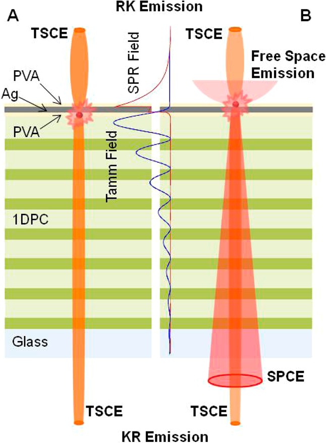
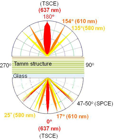
As shown schematically, TSCE with 637 nm emission maximum is expected to couple to surface to normal from this structure, whereas the surface plasmon-coupled emission (SPCE) shows typical circular cone emission at about 48° off-axis from surface normal. Free space emission is isotropic above the surface. Also shown in the figure are Tamm (blue line) and SPR (red line) field locations in the structure.
Experimental Methods
Materials
Nile Blue (NB), sulforhodamine 101 (S101), rhodamine B (RhB), poly(vinyl alcohol) (PVA, MW 13 000–23 000), and silver metal (purity 99.999%) were purchased from Sigma-Aldrich. Glass microscope slides were obtained from VWR. Nanopure deionized water was used for all solution preparations.
Simulations
Reflectance spectra were simulated using TFCalc (Software Spectra Inc.). The optical constants for silver were taken from ref (34) and for SiO2 and Si3N4 were from ref (24).
Substrate Preparation
Fabrication of the Tamm structure starts with making a 1DPC consisting of alternate low and high dielectric layers, which are fabricated using well-known thin-film deposition methods.35−37 We used plasma-enhanced chemical vapor deposition (PECVD) to fabricate alternate layers of SiO2 and Si3N4 on standard microscope slides. Prior to PECVD, the glass slides were cleaned with piranha solution and washed with nanopure deionized water. Then the slides were dried with air stream. We used SiO2 and Si3N4 as the low (L) and high (H) refractive index dielectrics, respectively. Except the top SiO2 layer, which has a thickness of 152 nm, the thicknesses of all SiO2 and Si3N4 layers of the structure were 126 and 78 nm, respectively. The sequence of layers on the glass slide is (HL)7-PVA-Ag-PVA (Figure 1). Tamm structures reported previously were usually consists of a truncated Bragg reflector, which has the high refractive index material for the top dielectric layer.31−33,38 We used similar metal-coated Bragg reflector for our previous work.30 However, our simulations results revealed that using the high refractive index dielectric is not a mandatory requirement for a Tamm state, and thus a Bragg reflector with a low refractive index dielectric top layer can also be used in the Tamm structure as in our present study. We found no difference in the either field location or the properties of both the Tamm structures we developed. Also we chose to use SiO2 for the top layer because it has the similar dielectric constant as PVA. The dimensions of the layers were selected based on reflectance simulations.
Figure 1.
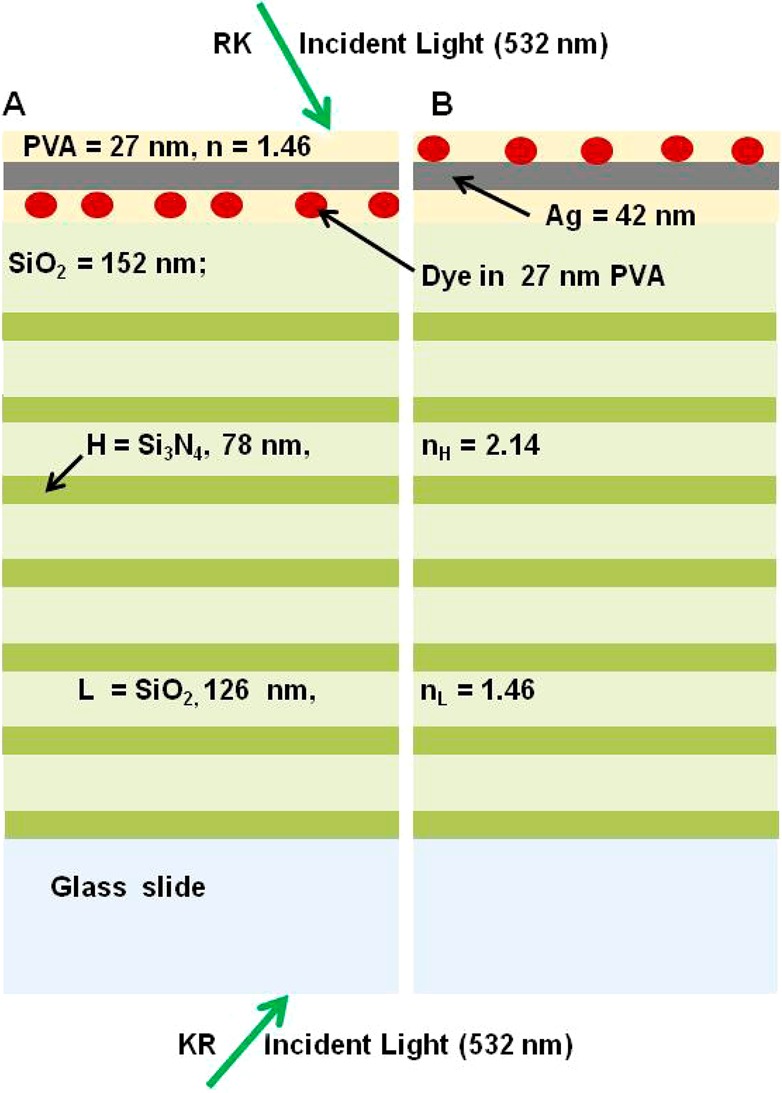
Schematic for the Tamm structure with two PVA layers. The dye is either located below (A) or above (B) the Ag film.
In the present study we used two dye locations, above and below the metal film (Figure 1). In order to have the same overall substrate thickness, we used two PVA layers, one below and one above the metal layer. In the first case we used dye dispersed in the bottom PVA layer (Figure 1A), and in the second case the dye is dispersed in the top PVA layer (Figure 1B). The above fabricated dielectric [(Si3N4–SiO2)7] 1DPC was first coated with a 27 nm PVA layer, with or without the dye, and then we coated a 42 nm thick silver layer by vapor deposition. We used an Edwards Auto 306 vacuum evaporation chamber under high vacuum (<5 × 10⁻⁷ Torr) for the deposition of the silver layer. The deposition rate (∼1.0 nm/min) was adjusted by the filament current, and the thickness of the deposited film was measured with a built-in quartz crystal microbalance. The Tamm structure was then spin-coated with a second 27 nm of PVA layer. Once again we used PVA with or without the dye depending on the set of substrates we are fabricating. We used 0.5% aqueous PVA solution (MW =16 000–23 000), 1000 rpm for 1 min, which yielded a thickness of 27 nm.24,39 The dye concentrations in the PVA solutions are ∼1 μM. The actual thickness and optical constants of the layers were determined using an N and K Model 1200 spectrometer, and the obtained data are in agreement with those reported previously.24
Tamm states only exist in a limited spectral range where the optical energy cannot exit from the top metal surface and cannot propagate into the substrate due to the PBG. To cover a range of wavelengths within and outside the Tamm states, we selected three fluorophores: Nile Blue (NB), sulforhodamine 101 (S101), and rhodamine B (RhB). NB, S101, and RhB show broad emission spectra with a band maximum of 670, 610, and 580 nm, respectively. As will be seen from the simulations and experimental results, the emission maxima of S101 and RhB are within the wavelength range of the Tamm state of our structure. In contrast, only part of the emission spectrum of NB is within the Tamm state coupling range. As a result only the short-wavelength region of the NB emission should overlap in energy and couple with the Tamm state. Angle-dependent fluorescence intensities and emission spectra were collected using the rotary stage described previously.6,7 Excitation was obtained from a CW 532 nm Nd–YVO4 laser. The emission was collected using Model SD2000 Ocean Optics spectrometer with a 1 mm diameter optical fiber (NA 0.22) placed 2 cm from the sample. Polarizers were placed between the sample and fibers as needed. A 550 nm long-pass emission filter was used to remove scattered light from the 532 nm excitation.
Optical Geometry for Measurements
The optical geometry for measurements on surfaces is complex, and the vocabulary is not standardized. To avoid ambiguities, Figure 2 shows the experimental geometry used in the present study. The laboratory vertical direction is the out-of-plane axis in Figure 2. The Tamm structure is affixed on a hemicylindrical prism (with index matching fluid, glycerol), which is mounted on the rotary stage. As can be seen from the results, this prism is not strictly necessary with a Tamm state, but we retained the prism to be consistent with our previous measurements and to avoid changes in angle of incidence or emission. Additionally, the use of a prism allowed detection of the SPCE emission from the Tamm structure with the dye above the metal film. Incident light through the prism is called the Kretschmann (KR) configuration. Light incident from the sample side is called reverse Kretschmann (RK) illumination. We used the same notation for emission. That is the emission measured through the prism is called KR emission and from the air side is called RK or free-space emission (Figure 2). The polarization is defined relative to the plane of incidence. The E-field for TE or S-polarized light is parallel to the sample surface which is out of the plane of Figure 2. The E-field for TM or P-polarized light is in the plane of incidence. An angle of 0° is perpendicular to the KR side of the sample. An angle of 180° is perpendicular to the RK or air side of the sample.
Figure 2.
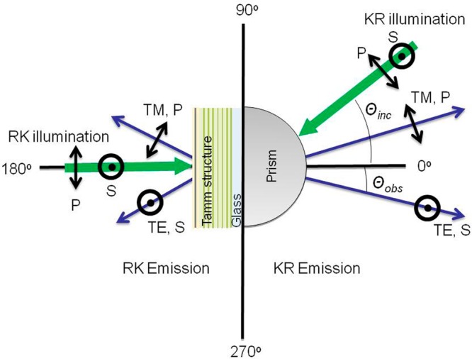
Experimental geometry and polarizations used for the present measurements. The light green schematic represents the Tamm structure shown in Figure 1.
Results and Discussion
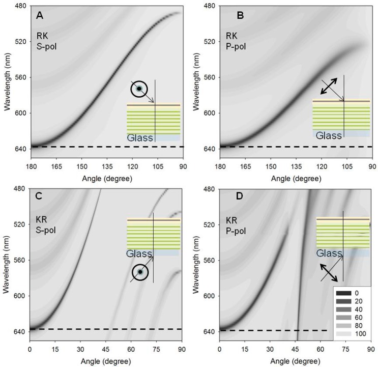
Prior to describing the coupled emission, it is informative to examine the mode profile of our Tamm structure. These profiles are often presented on frequency (energy) vs wavevector axes. We chose to use wavelength versus incident angle axes which are more directly connected to the experimental results. These dispersion diagrams for the reflectivity of our Tamm structure are shown in Figure 3 where the dark shade indicates a decrease in reflectivity and the presence of an optical mode. The width and strength of the mode can be judged by the width and darkness of the shading. Consider first the top two panels (panels A and B) in Figure 3, which show the reflectivity for S- and P-polarized illumination for light incident on the sample side (RK) of the structure. If the sample was the metal film on a plain glass substrate, there would be complete reflection at all angles and no dark region could be observed.30 The dark regions in these two panels are indeed due to coupling of the incident light into the structure at nearly all angles from the surface normal (180° with either S- or P-polarized light). Changes in the angle of incidence away from the normal result in a blue-shift of the wavelength resonances. These decreases in reflectivity are due to the Tamm states. The weaker bands at shorter wavelengths are due to coupling to internal modes in the 1DPC which are not directly influenced by the metal film.
Figure 3.
Calculated reflectivity dispersion diagrams for the Tamm structure shown in Figure 1 using RK, S- (A) or P- illumination (B) or KR, S- (C) or P-illumination (D). Insets show the illumination geometries and light polarizations. Also shown in the figure is the reflectivity scale, from 0 to 100%, of the dispersion diagrams. The horizontal dotted lines show the wavelength used in Figure 4.
The lower two panels (panels C and D) in Figure 3 reveal more complex optical properties for the structure with KR illumination, through the prism. The Tamm states are the dark hyperbolic curves which start at about 640 nm of 0° incidence. An additional resonance is seen for P-polarized illumination which is not seen for S-polarized illumination. This nearly vertical dark region in Figure 3D is due to surface plasmons (SP) on the distal surface of the metal (sample side). As occurs for metal films on plain glass, the SP resonances occurs only for P-polarized light. The other dark regions of the dispersion plots represent other optical modes which localized in various regions of the structure. These dispersion diagrams show that hyperbolic-like Tamm modes are accessible from either side (i.e., RK and KR side) of the sample and for S- or P-polarized light. Additionally, the SP mode is only weakly dependent on wavelength, whereas the Tamm states are highly sensitive to incident angle and wavelength. This result suggests TSCE will display a useful wavelength separation based on the observation angle.
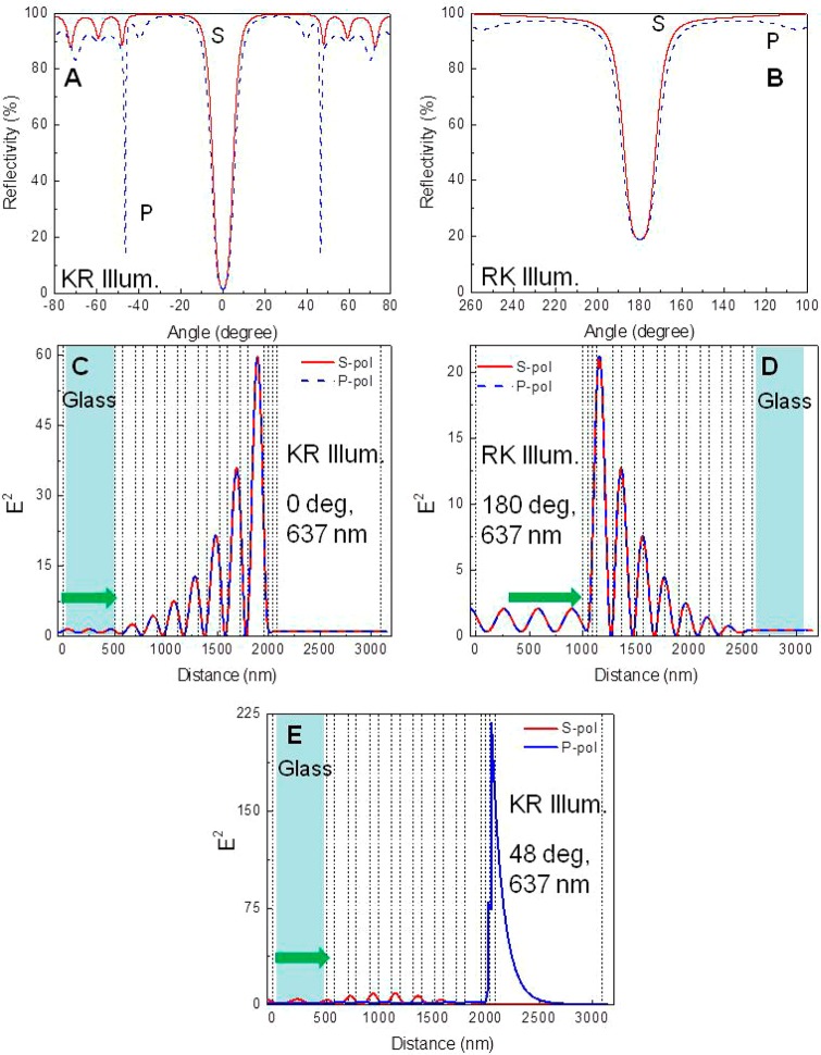
We assigned the modes shown in Figure 3 by examination of the electric field intensities (E2) within the structure. Figures 4A,B show the angle-dependent reflectivity of our Tamm structures for 637 nm illumination, which is where the Tamm resonances is normal (0° or 180° to the sample plane). Panels C and D show that the field intensity is highest in the dielectric layer below the metal structure and decays exponentially into the structure, which is a feature characteristic of Tamm states. The same field location is found with KR or RK illumination, but the field intensity is lower with RK illumination, most probably due to reflectance by the metal layer. It is interesting to note that the Tamm fields penetrate very weakly into the sample space, which suggests this region is not optional for obtaining coupled emission. Figure 4A, the Tamm structure with KR illumination, shows an additional drop in reflectivity at 48° for P-polarized but not for S-polarized light. Figure 4E shows the field is localized at the metal surface with an evanescent field decaying into the sample space. This shows the P-polarized KR resonance drop of Figure 4A is due to surface plasmons and not to another Tamm state or internal modes of the structure.
Figure 4.
Calculated angle-dependent reflectivity for the Tamm structure shown in Figure 1 with 637 nm incident light, KR (A) or RK (B) illumination. The calculated electric field intensity distributions for KR (C) or RK (D) illumination at 0°. Calculated field intensity distribution in the structure with KR, 637 nm light illumination using 48° (E).
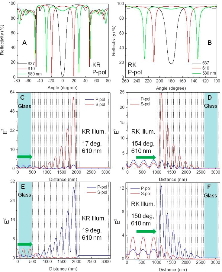
The dispersion diagrams in Figure 3 showed that the Tamm states depend strongly on wavelength and incident angle. Figure 5 shows the P-polarized reflectivity from our structure for three different wavelengths: 637, 610, and 580 nm. The latter two wavelengths are the peak maximum of S101 and RhB, respectively, used in this study and are within the Tamm state coupling range. At 610 and 580 nm we found new dips in reflectivity at angles ranging from 17° to 30° from the normal in each direction. The resonances appear for both the S- and P-polarized illumination, and the angles are dependent on wavelength. We also used NB whose emission maximum is about 670 nm. The maximum allowed wavelength for the Tamm state resonance with our structure is 637 nm. As it can be seen from Figure 3, no Tamm resonances are seen for the wavelengths above 637 nm. Above this wavelength the reflectivity at 0° or 180°is near 100%. Accordingly, we anticipate that NB emission with 670 nm peak maximum may not couple with our Tamm structure. Figure S1 shows the angle-dependent reflectivity for the same three wavelengths using S-polarized light illumination. We noticed similar results for S-polarized illumination except no reflectivity dip corresponding to the surface plasmon resonances. Surprisingly, the reflectivity is not the same for KR and RK illumination, and the angular shift is larger for the RK than for the KR illumination. A similar trend is observed for the 610 and 580 nm light illumination. Additionally, the wavelength dispersion of the Tamm state is larger than that found for the SPR state (Figure 5A). For example, the reflectivity dip at 0° or 180° incidence that is seen for 637 nm shifts off-axis by ±17° for S-polarized, KR illumination using 610 nm incident light and is shifted off-axis by ±19° for the corresponding P-polarized incidence light (Figure 5B). The corresponding change in wavelength shifts SPR angle only by 2°. Comparison of Figure 5 and Figure S2 shows that the resonance is slightly smaller for S-polarized as compared to P-polarized illumination. This difference can be used to create Tamm fields which depend on the incident polarization. For example, S-polarized illumination at 25° and 140° results in Tamm fields while P-polarized light at the same angle does not couple to a Tamm state (Figure S2), and the converse is true for illumination at 28° and 134°. From these simulations it is clear that the Tamm structures can provide the function of several separate optical components. The Tamm structure can collect the emission, beam the emission toward a detector with wavelengths separated by angle, and suppress longer wavelength emission where a Tamm state does not exist.
Figure 5.
Calculated reflectivity for the Tamm structure for different incident wavelengths using P-polarized KR (A) and RK (B) illumination. Electric field intensities in the Tamm structure for 610 nm incident light (C–F). KR (C, E) and RK (D, E) illumination. Calculated angle-dependent reflectivities for S-polarized illumination are shown in Figure S1. Field intensities for 580 nm are shown in Figure S2.
Absorption Spectra of the Tamm Structure
The 1DPC and subsequent Tamm structures were fabricated as described in the Experimental Methods. Figure 6A shows the incident angle-dependent apparent absorption spectra of Tamm structure with KR illumination. The spectrum with RK illumination was almost identical (not shown). The Tamm structure shows increased transparency near 640 nm. The feature is not present in the 1DPC structure without the silver film (Figure S3A), demonstrating its origin is due to a Tamm state. Others have reported similar spectral shapes in Tamm structures.40,41 This assignment is further confirmed by the calculated reflectivity spectra for KR (Figure 6B) and RK (Figure S3B) illumination. The doublet seen for 30° KR and 150° RK are due to the S- and P-polarized Tamm states. These states can also be seen at higher incident angles (135° and 120°) with RK illumination (Figure S3B). More complex behavior was found for 45° and 60° KR illumination where doublets appear to be present but without symmetrical shapes. We found this effect could be explained by close examination of the dispersion diagram (Figure 3D). The Tamm and SPR states become closer together but do not cross, suggesting coupling between the Tamm and SPR modes. Upon close examination of the literature, we found that Tamm–surface plasmon coupling had been previously predicted and observed.42
Figure 6.
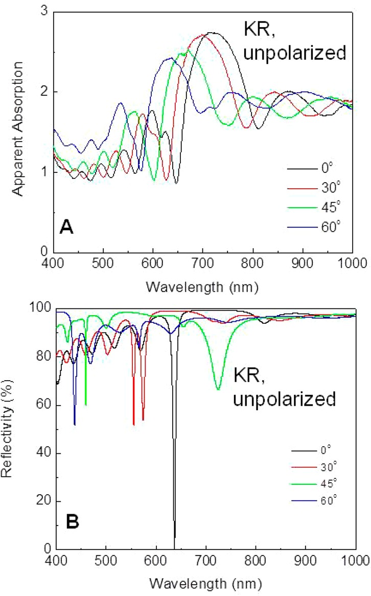
Measured apparent absorption of the Tamm structure with KR illumination (A). Calculated reflectivity of the Tamm structure using unpolarized KR illumination (B). The dual peaks are due to the S- and P-polarized resonances. Apparent absorption spectra for 1DPC with no Ag layer and calculated reflectivity for Tamm structure for unpolarized RK illumination are shown in Figure S3.
Emission from Probes on the Tamm Structure
We use the simulated properties of the Tamm structure (Figures 3–5) to design the Tamm structure and interpret the spatial and spectral properties of probes on the Tamm structure when positioned above or below the metal film. Initial experiments were performed using NB which has an emission maximum of 670 nm that is slightly longer than the longest wavelength resonance of the 637 nm of our Tamm structure. The NB was positioned in the 27 nm PVA layer below the metal film (Figure 7, inset). The sample was illuminated under conditions to maximize coupling of the 532 nm incident light into the Tamm structure. The emission was observed at a wavelength which gave the highest initial intensity which in this case was 637 nm with 0° or 180° observation (Figure 7). The 637 nm observation wavelength is different from the free-space emission maximum of 670 nm (discussed below). For KR P-polarized illumination highly directional emission was observed normal to the surface in both directions. The emission intensities in both directions were nearly equal even though the RK emission had to pass through a silver film, which on a plane slide would have an optical density near 1.5 or transmission of only 3%. This result indicates efficient coupling of fluorophores under the metal film to the Tamm mode in the structure. The P-polarized emission is about 40% larger than the S-polarized emission. For S-polarized excitation the directional intensities were similar, but the S-polarized emission intensity was similarly larger than the P-polarized intensity. This result may indicate the excitation and/or emission of probes in the Tamm region depend on orientation of the transition dipoles relative to the sample plane. We suspect the smaller off-axis peaks are due to coupling to internal modes of the Tamm structure, but this requires additional experimentation.
Figure 7.
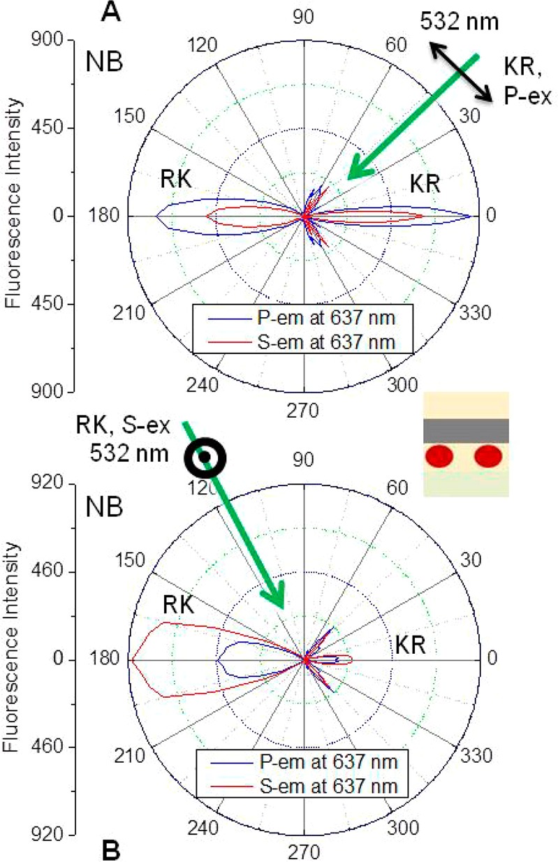
Angle-dependent Nile Blue emission intensities at 637 nm on the Tamm structure with KR illumination at 43° (A) and with RK illumination at 115° (B). Inset shows the Nile Blue location in the 27 nm PVA film below the metal layer.
Next this NB sample was illuminated from the RK direction at 115° which couples to the Tamm mode from the RK direction. This resulted in directional emission normal to the surface with the RK emission being dominant (Figure 7B). The RK emission displayed a larger angular distribution than the KR emission, a feature we observed with the other two probes (below). The field simulations indicated similar intensities and spatial distributions with RK and KR illumination (Figure 4), but RK illumination resulted in much higher RK emission. At this time we cannot explain this difference. Importantly, we did not observe significant SPCE emission which would occur near 48° from the normal. The small peaks near this angle were not strongly polarized as would occur for SPCE. The absence of SPCE can be understood because the NB is located under the metal film and the SP mode exists above the metal film. Nonetheless, the absence of SPCE emission is not obvious because fluorophores near the bottom of the metal film could induce SPs, which in turn radiate into the substrate. This effect may contribute to the smaller high-angle peaks in Figure 7.
Next we tested the NB emission intensity distribution from the Tamm structure when the NB is dispersed in the PVA layer on the top of the metal film (Figure S4). In this case there are high P-polarized emission intensities near 46° with either KR or RK excitation. The angle and polarization of this emission indicate that this is due to coupling to the P-polarized surface plasmons. Additionally, some of the emission is coupled to the Tamm state and resulted in directional emission at surface to normal, with maximum intensity at 0° and 180°. The spectral features including wavelength dependence on the emission coupling angle are similar to that observed with the dye below the metal film. At this time we do not understand the slightly off-normal emission for the P-polarized TSCE. The dye above the structure shows P-polarized SPCE intensity that is twice larger than the TSCE observed at 0 or 180°. The origin of this difference might be due to the spatial distribution of the electric field intensities of Tamm state and SPR modes. The Tamm state electric field maxima are inside the structure and show weaker coupling efficiencies with the fluorophores positioned on top of the metal film, and the surface plasmon resonances have high electric field intensity on the metal surface and extend into the sample resulting in more intense P-polarized SPCE emission (Scheme 1). We confirmed this explanation by direct comparison of the emission from samples with the NB above and below the metal film, where the probe below the metal showed a 5-fold higher intensity (Figure 8A).
Figure 8.
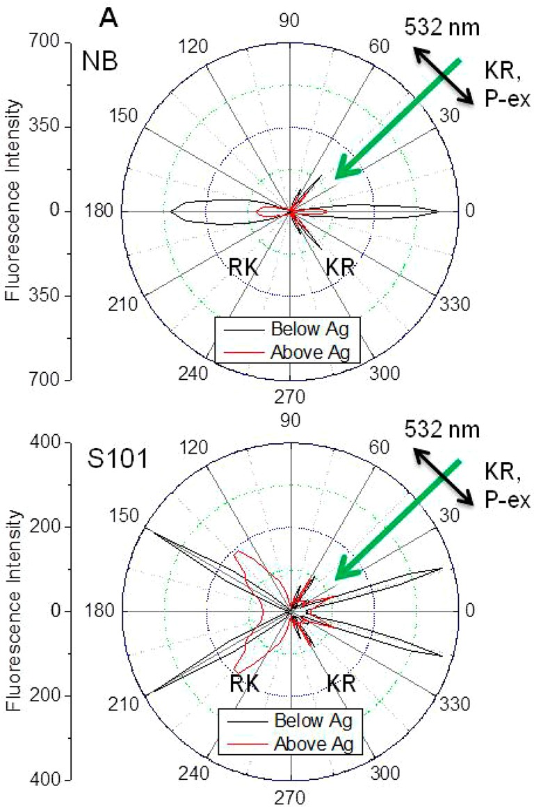
Effect of probe location (above or below Ag layer) on the angle-dependent S-polarized emission intensity distributions of NB (A) and S101 (B). P-polarized KR illumination at 43°.
The dispersion diagrams in Figure 3 showed a strong dependence of the Tamm mode on the angle of incidence. This suggests that emission at different wavelengths will appear at different angles. We tested this possibility using NB located below the metal and thus directly in location of the Tamm mode. The NB emission maxima were found to be strongly dependent on the observation angle in both the KR and RK directions (Figure 9). We noticed similar spectral behavior from NB on this structure using RK, KR for both S- or P-polarized light. The corresponding emission spectral behavior that we observed with NB from this structure with RK illumination is shown in Figure S5. We noticed comparable spectral coupling and angular shifts from the structure with the NB in the PVA layer above the metal film. The representative spectra are shown in Figure S6 where NB is excited using KR, 532 nm light at 43° incidence. Notably, in all these spectra there is no emission of the long wavelength emission occurs because the Tamm mode does not exist above 637 nm and confirms that the emission from this structure is indeed TSCE.
Figure 9.
Tamm state-coupled emission of Nile Blue with S- (A, B) and P-polarized (C, D) observation. P-polarized KR 532 nm illumination at 43° is used. The dotted blue lines show the Nile Blue emission from PVA on glass normalized to the maximum intensity from the Tamm structure. The inset shows the probe location below the Ag layer.
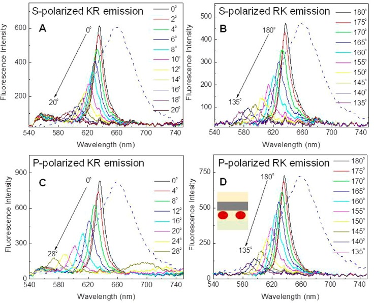
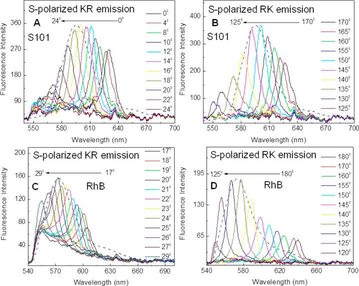
To understand the effect of wavelength on the Tamm state-coupled emission, we examined our Tamm structure with S101 and RhB. Both S101 and RhB on glass show broad emission spectra with shorter emission maxima of 610 and 580 nm, respectively, as compared to NB. In Figure 5 we showed that the decrease in wavelength from 637 nm to 610 or 580 nm shifts the Tamm resonance from surface to normal (0°) to off-axis angles and that difference resonance angles were expected for S- and P-polarized light. Accordingly, we anticipated, the S101 and RhB emission coupled to the Tamm structure should result the maximum intensity at the off-axis angles. Figure 10 shows angle-dependent emission intensity for S101 and RhB from the Tamm structure using KR illumination at an incident angle of 43° with the dye located in the below the metal layer. The TSCE emission from S101 in the KR direction is no longer perpendicular to the surface but occurs at about ±17° from the normal. The corresponding emission from the RhB is about ±28° from the surface normal. For both probes the emission spectra which are strongly dependent on the observation angle (Figure 11). The RK emission also shows maximum emission at off-axis angles, but the angular-shift is more pronounced as compared to that of KR emission. In the RK direction, TSCE from S101 has the maximum emission at 150° and that of RhB is at about 133°, which are consistent with the angular shifts shown in Figure 5. We once again noticed relatively equal emission coupling intensities to both sides of the substrate with KR illumination whereas RK illumination resulted in the stronger coupling toward sample side. Figure S7 shows the emission intensity distributions for S101 and RhB from the Tamm structure with the dye located below the metal layer using RK illumination. The S-polarized emission shows more intense coupling toward the RK side, with both RK and KR illuminations (Figure 10 and Figure S7). Once again, no SPCE was observed near 48° from the Tamm structure with the dye below the metal layer. As stated earlier, this is due to inaccessibility of the surface plasmon modes to excite the probes located below the metal layer.
Figure 10.
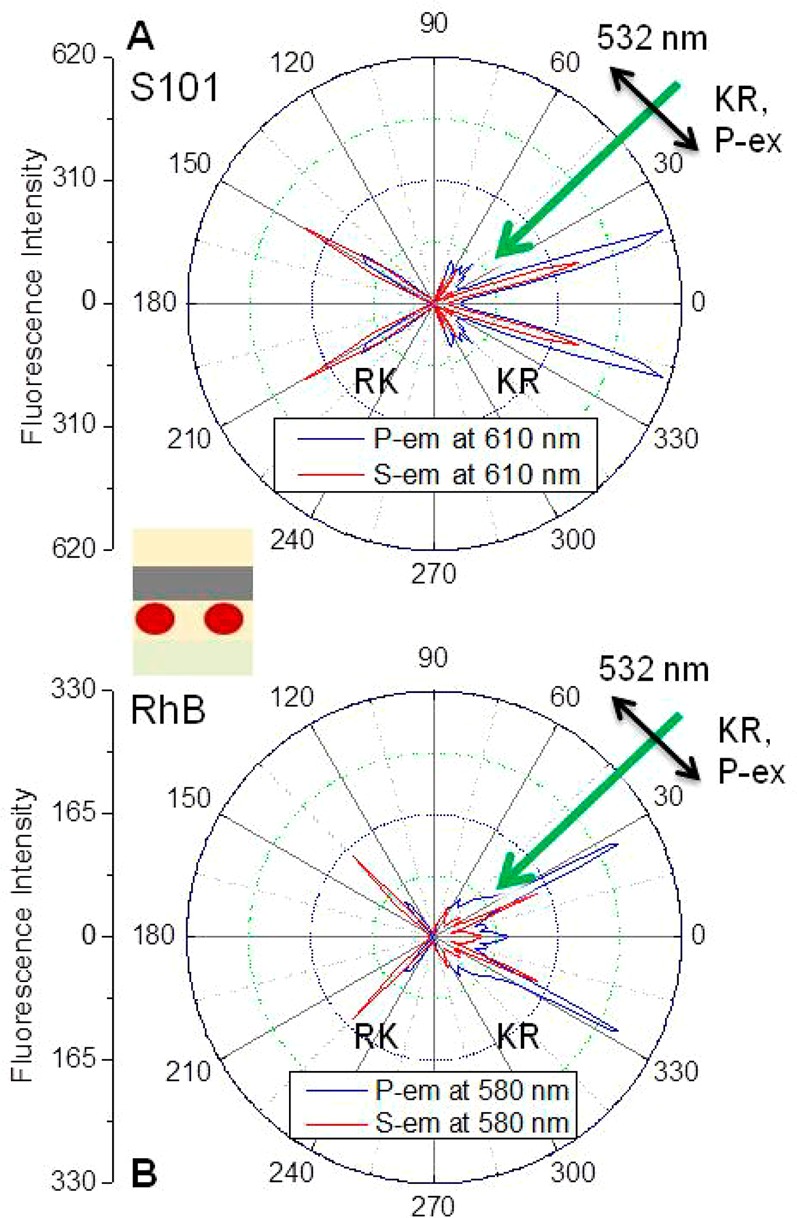
Angle-dependent S101 emission intensity at 610 nm (A) and RhB emission intensity at 580 nm (B) using P-polarized KR illumination at 43°. Inset shows the dye S101 or RhB location in the 27 nm PVA film below the metal layer.
Figure 11.
S-polarized KR (A) and RK emission spectra (B) of S101 and corresponding RhB emission (C and D, respectively) at different observation angles. 532 nm KR, P-polarized light illumination at 43° is used. The dashed blue lines in the top panels show the S101 emission from PVA layer on glass, and in the bottom panel is the corresponding RhB emission.
We also examined the Tamm state-coupled emission from the S101 and RhB located in PVA layer above the metal film of the structure. Similar to NB, S101 and RhB show large surface plasmon-coupled, P-polarized emission intensities near 46° as suggested by the simulations in Figure 4. Also, some of the emission is coupled to the Tamm state and resulted in directional emission at off-axis angles, within the light line. The spectral features including wavelength dependence on the coupling angle are similar to that observed with the dye below the metal layer and can be ascribed to the electric field intensities and spatial location of the Tamm state and SPR modes of the structure. Accordingly, we noticed about 5-fold larger TSCE intensities for S101 (Figure 8B) and RhB (not shown) from the bottom dye structure as compared to that from the structure with the top dye. This can be explained based on Tamm state mode distribution in the structure.
Figure 11 shows the S-polarized TSCE emission spectra of Tamm structure with S101 and RhB from various observation angles while using KR illumination at 43°. To compare the emission spectral features of the dyes on glass and Tamm structure, we show the intensity normalized S101 and RhB emission spectra from the glass surface in the figure. Once again, the emission spectrum from the Tamm structure is sharp as compared from glass. The maximum S-polarized emission intensity for S101 is noticed at 17° and 143°, and the corresponding RhB emission is seen at 25° and 133°. The angle-dependent emission maxima of S101 and RhB shift to shorter wavelengths with increasing observation angle. The sum of the emission spectra collected at various angles resembles the emission spectra of the probes from the glass. Small differences to note here are the relatively higher intensities in the red-region of the spectra are noticed from the Tamm structure. Similar shifts and intensities changes were found for both the S- and P-polarized KR and RK emission. Figure S8 shows the P-polarized emission spectra of S101 and RhB from the structure. Additionally, we noticed similar spectral coupling and angular shifts from the structure with the S101 and RhB in the PVA layer above the metal film (data not shown).
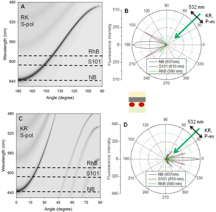
At first glance the emission from fluorophores on the Tamm structure can appear complex. To illustrate the connections between the dispersion diagrams and distribution of the emission, we combined representative examples in Figure 12. The dashed lines on the dispersion diagrams represent the emission maxima of the three probes used in the present study. The right-side panels show the angle-dependent emission intensities measured at the emission maxima of the probes. Each probe displays peak intensity at different angles, with shorter wavelengths being at larger angles from the normal. The angular separation is more pronounced for RK emission as compared to the KR emission. TSCE could not be observed for wavelengths above 640 nm. The absence of TSCE from NB spectra above 640 nm is consistent with our dispersion calculations, which show a Tamm state does not exist in our structure for wavelengths above 640 nm. As stated earlier, we found the similar angular distributions for the dyes above the metal film (data not shown).
Figure 12.
Calculated S-polarized dispersion diagrams for RK (A) and KR illumination (C). Panels B and D show the observed angle-dependent S-polarized emission intensity of NB, S101, and RhB at the indicated wavelengths from the Tamm structure. The dye is located below the metal film as shown in the inset schematic.
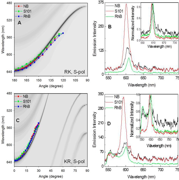
The angle-dependent emission maxima of the dyes, NB, S101, and RhB, for RK and KR observations are summarized in Figure 13. The emission maxima are in excellent agreement with the resonances found from the reflectivity calculations. It is interesting to note that the almost same emission maxima are noticed for a given observation angle, independent of the fluorophore. For instance, although the emission intensities are different for different probe, we noticed same emission maximum with all three probes while observing at 150° (Figure 13B). And it is the same case with 18° observation as show in Figure 13D. In other words, the same emission maximum of 637 nm is noticed for NB, S101, and RhB with 0° observation. Similarly, the same 600 nm emission is noticed for NB, S101, and RhB at about 18°. The small discrepancy in the data presented in this figure might be due to the experimental error associated with the Tamm structure fabrication that including two PVA layers. Also, the actual optical parameters of the layers of the structure may be slightly different from the parameters used for the dispersion calculations. This result shows that the dependence of wavelength on angle represents the optical properties of the Tamm structure and not on the emission spectra of the fluorophores. This is not an obvious result because probe coupling to the optical modes can occur by other mechanisms which involve strong coupling between the probe excited states and optical modes, which results in two new nonoverlapping states.43−45 Another possible effect is spectral shifts due to the high photonic mode density (PMD) at the edges of the photonic band gaps in our structure.46,47 These effects have been reported to shift the total emission spectra of fluorophores from 3D colloidal photonic crystals due to a rapid change from low to high PMD across the emission wavelength.48,49 At this time we cannot exclude a contribution of this effect to the present data.
Figure 13.
Calculated S-polarized light dispersion diagrams for RK (A) and KR (C) and observed angle-dependent shift in S-polarized emission maxima of Nile Blue (NB), S101, and RhB from the Tamm structure. Panels B and D show the emission spectra of three dyes observed at angle of 150° for RK and 18° for KR S-polarized emission. The inset figures in panels B and D are the corresponding intensity normalized spectra from all three probes. The dye location is below the metal layer.
Conclusion
This work reports the fabrication of large area hybrid photonic–plasmonic structure, Tamm structure, using a 1DPC with a top 42 nm silver layer. The Tamm structure shows both TP and SP modes. The field location for the Tamm mode is in the dielectric layer below the metal film, whereas the corresponding field location for the surface plamon modes is on the metal film, at the Ag–air interface. We used two probe locations, below and above the metal film, to see the fluorophore interactions with both Tamm and SP modes and thus the probe location dependent Tamm and surface plasmon coupling efficiencies. We used three probes, Nile Blue, S101, and RhB, with different emission spectral overlap with the Tamm modes. The probes below the silver show only TSCE with 637 nm emission wavelength, which is normal to the surface. On the other hand, the structures with probes above the metal layer exhibit both TSCE and SPCE. The observed results are in agreement with the simulation. TSCE exhibits both S- and P-polarization, can couple to ether sides of the sample, and can be excited using RK and KR illuminations. The TSCE angle is more sensitive to the emission wavelength than that observed for SPCE. We believe the combined plasmonic–photonic structures as described herein provide opportunities for spatial and spectral control of emission without the aid of external optical devices that operate on the free-space emission. Our Tamm structure used only thin films deposited by vapor deposition and spin-coating methods. The Tamm modes are assembled within the light line, from either direction, and do not require a prism to couple the light into or out of the structures. These favorable features indicate one-dimensional Tamm structures can be readily introduced into existing instruments for biological and clinical testing using high-throughput formats. Tamm structure offers many additional opportunities to improve the sensitivity of fluorescence detection. For example, TPPs are thought to propagate slowly which may provide additional time for interaction with or interaction of fluorphore in the Tamm fields.38,50 Tamm states have been shown to increase light transmission through the nanoaperture in metal film,51 which has implications for DNA sequencing.52 Tamm structures can be used for quantum well lasers53 and provide increased nonlaser optical effects.54,55 The use of Tamm state provides an opportunity for a new generation of fluorescence instrumentation based on near-field control of fluorescence.
Acknowledgments
This work was supported by NIH Grants RO1HG002655, RO1EB006521, and RO1HG005090. We also acknowledge the support of the Maryland Nano Center and its FabLab.
Supporting Information Available
Figures S1–S8 describing the Tamm state properties. This material is available free of charge via the Internet at http://pubs.acs.org.
The authors declare no competing financial interest.
Funding Statement
National Institutes of Health, United States
Supplementary Material
References
- Lakowicz J. R. Radiative Decay Engineering: Biophysical and Biomedical Applications. Anal. Biochem. 2001, 298, 1–24. [DOI] [PMC free article] [PubMed] [Google Scholar]
- Lakowicz J. R. Plasmonics in Biology and Plasmon-Controlled Fluorescence. Plasmonics 2006, 1, 5–33. [DOI] [PMC free article] [PubMed] [Google Scholar]
- Lakowicz J. R. Radiative Decay Engineering 5: Metal-Enhanced Fluorescence and Plasmon Emission. Anal. Biochem. 2005, 337, 171–194. [DOI] [PMC free article] [PubMed] [Google Scholar]
- Demchenko A. P. Nanoparticles and Nanocomposites for Fluorescence Sensing and Imaging. Methods Appl. Fluoresc. 2013, 1, 022001–1/28. [DOI] [PubMed] [Google Scholar]
- Lakowicz J. R.; Shen Y.; D’Auria S.; Malicka J.; Fang J.; Gryczynski Z.; Gryczynski I. Radiative Decay Engineering 2. Effects of Silver Island Films on Fluorescence Intensity, Lifetimes, and Resonance Energy Transfer. Anal. Biochem. 2002, 301, 261–277. [DOI] [PMC free article] [PubMed] [Google Scholar]
- Lakowicz J. R. Radiative Decay Engineering 3. Surface Plasmon-Coupled Directional Emission. Anal. Biochem. 2004, 324, 153–169. [DOI] [PMC free article] [PubMed] [Google Scholar]
- Gryczynski I.; Malicka J.; Gryczynski Z.; Lakowicz J. R. Radiative Decay Engineering 4. Experimental Studies of Surface Plasmon-Coupled Directional Emission. Anal. Biochem. 2004, 324, 170–182. [DOI] [PMC free article] [PubMed] [Google Scholar]
- Fort E.; Gressillon S. Surface Enhanced Fluorescence. J. Phys. D: Appl. Phys. 2008, 41, 013001–1/31. [Google Scholar]
- Xie F.; Drozdowicz-Tomisa K.; Goldys E. M. A Method to Assess Modifications of Fluorophore Radiative Rate by Plasmonic Structures. Chem. Phys. Lett. 2008, 466, 186–188. [Google Scholar]
- Kroekenstoel E. J. A.; Verhagen E.; Walters R. J.; Kuipers L.; Polman A. Enhanced Spontaneous Emission Rate in Annular Plasmonic Nanocavities. Appl. Phys. Lett. 2009, 95, 263106–1/3. [Google Scholar]
- Fu Y.; Lakowicz J. R. Modification of Single Molecule Fluorescence Near Metallic Nanostructures. Laser Photonics Rev. 2009, 3, 221–233. [DOI] [PMC free article] [PubMed] [Google Scholar]
- Zhang J.; Fu Y.; Chowdhury M. H.; Lakowicz J. R. Single-Molecule Studies on Fluorescently Labeled Silver Particles: Effects of Particle Size. J. Phys. Chem. C 2008, 112, 18–26. [DOI] [PMC free article] [PubMed] [Google Scholar]
- Anger P.; Bharadwaj P.; Novotny L. Enhancement and Quenching of Single-Molecule Fluorescence. Phys. Rev. Lett. 2006, 96, 113002–1/4. [DOI] [PubMed] [Google Scholar]
- Kinkhabwala A.; Yu Z.; Fan S.; Avlasevich Y.; Mullen K.; Moerner W. E. Large Single-Molecule Fluorescence Enhancements Produced by a Bowtie Nanoantenna. Nat. Photonics 2009, 3, 654–657. [Google Scholar]
- Tam F.; Goodrich G. P.; Johnson B. R.; Halas N. J. Plasmonic Enhancement of Molecular Fluorescence. Nano Lett. 2007, 7, 496–501. [DOI] [PubMed] [Google Scholar]
- Chen Y.; Munechika K.; Giner D. S. Dependence of Fluorescence Intensity on the Spectral Overlap between Fluorophores and Plasmon Resonant Single Silver Nanoparticles. Nano Lett. 2007, 7, 690–696. [DOI] [PubMed] [Google Scholar]
- Akbay N.; Lakowicz J. R.; Ray K. Distance-Dependent Metal-Enhanced Intrinsic Fluorescence of Proteins Using Polyelectrolyte Layer-by-Layer Assembly and Aluminum Nanoparticles. J. Phys. Chem. C 2012, 116, 10766–10773. [DOI] [PMC free article] [PubMed] [Google Scholar]
- Szmacinski H.; Badugu R.; Lakowicz J. R. Large Fluorescence Enhancements of Fluorophore Ensembles with Multilayer Plasmonic Substrates: Comparison of Theory and Experimental Results. J. Phys. Chem. C 2012, 116, 21563–21571. [DOI] [PMC free article] [PubMed] [Google Scholar]
- Szmacinski H.; Badugu R.; Lakowicz J. R. Fabrication and Characterization of Planar Plasmonic Substrates with High Fluorescence Enhancement. J. Phys. Chem. C 2010, 114, 21142–21149. [DOI] [PMC free article] [PubMed] [Google Scholar]
- Dionne J. A.; Atwater H. A. Plasmonics: Metal-Worthy Methods and Materials in Nanophotonics. MRS Bull. 2012, 37, 717–724. [Google Scholar]
- Schuller J. A.; Barnard E. S.; Cai W.; Jun Y. C.; White J. S.; Brongersma M. L. Plasmonics for Extreme Light Concentration and Manipulation. Nat. Mater. 2010, 9, 193–204. [DOI] [PubMed] [Google Scholar]
- Jain P. K.; El-Sayed M. A. Plasmonic Coupling in Noble Metal Nanostructures. Chem. Phys. Lett. 2010, 487, 153–164. [Google Scholar]
- Stockman M. I. Nanoplasmonics: Past, Present, and Glimpse into Future. Opt. Express 2011, 19, 22029–22106. [DOI] [PubMed] [Google Scholar]
- Badugu R.; Nowaczyk K.; Descrovi E.; Lakowicz J. R. Radiative Decay Engineering 6: Fluorescence on One-Dimensional Photonic Crystals. Anal. Biochem. 2013, 442, 83–96. [DOI] [PMC free article] [PubMed] [Google Scholar]
- Zhang D.; Badugu R.; Chen Y.; Yu S.; Yao P.; Wang P.; Ming H.; Lakowicz J. R. Back Focal Plane Imaging of Directional Emission from Dye Molecules Coupled to One-Dimensional Photonic Crystals. Nanotechnology 2014, 25, 145202–1/10. [DOI] [PMC free article] [PubMed] [Google Scholar]
- Han L.; Zhang D.; Chen Y.; Wang R.; Zhu L.; Wang P.; Ming H.; Badugu R.; Lakowicz J. R. Polymer-Loaded Propagating Modes on a One-Dimensional Photonic Crystal. Appl. Phys. Lett. 2014, 104, 061115–1/5. [DOI] [PMC free article] [PubMed] [Google Scholar]
- Ballarini M.; Frascella F.; Michelotti F.; Digregorio G.; Rivolo P.; Paeder V.; Musi V.; Giorgis F.; Descrovi E. Bloch Surface Waves-Controlled Emission of Organic Dyes Grafted on a One-Dimensional Photonic Crystals. Appl. Phys. Lett. 2011, 99, 043302–1/3. [Google Scholar]
- Homola J., Ed.; Surface Plasmon Resonance Based Sensors; Springer: New York, 2006; Vol. 4, pp 1–251. [Google Scholar]
- Brongersma M. L., Kik P. G., Eds.; Surface Plasmon Nanophotonics; Springer: New York, 2007; 268 pp. [Google Scholar]
- Badugu R.; Descrovi E.; Lakowicz J. R. Radiative Decay Engineering 7: Tamm State-Coupled Emission Using a Hybrid Plasmonic-Photonic Structure. Anal. Biochem. 2014, 445, 1–13. [DOI] [PMC free article] [PubMed] [Google Scholar]
- Kavokin A. V.; Shelykh I. A.; Malpuech G. Lossless Interface Modes at the Boundary Between two Periodic Dielectric Structures. Phys. Rev. B 2005, 72, 233102–1/4. [Google Scholar]
- Kaliteevski M.; Iorsh I.; Brand S.; Abram R. A.; Chamberlain J. M.; Kavokin A. V.; Shelykh I. A. Tamm Plasmon-Polaritons: Possible Electromagnetic States at the Interface of a Metal and a Dielectric Bragg Mirror. Phys. Rev. B 2007, 76, 165415–1/5. [Google Scholar]
- Gaspar-Armenta J. A.; Villa F. Photonic Surface-Wave Excitation: Photonic Crystal–Metal Interface. J. Opt. Soc. Am. B 2003, 20, 2349–2354. [Google Scholar]
- Johnson P. B.; Christy R. W. Optical Constants of the Noble Metals. Phys. Rev. B 1972, 6, 4370–4374. [Google Scholar]
- Macleod H. A.Thin-Film Optical Filters; IoP Publishers: Philadelphia, 2001; 641 pp. [Google Scholar]
- Elshabini-Riad A. A. R.; Barlow F. D.. Thin Film Technology Handbook; McGraw-Hill: New York, 1997; pp 1–1/11.50. [Google Scholar]
- Heavens O. S.Optical Properties of Thin Solid States; Dover Publications: New York, 1955, 261 pp. [Google Scholar]
- Sasin M. E.; Seisyan R. P.; Kalitteevski M. A.; Brand S.; Abram R. A.; Chamberlain J. M.; Yu Egorov A.; Vasil’ev A. P.; Mikhrin V. S.; Kavokin A. V. Tamm Plasmon Polaritons: Slow and Spatially Compact Light. Appl. Phys. Lett. 2008, 92, 251112–1/3. [Google Scholar]
- Gryczynski I.; Malicka J.; Nowaczyk K.; Gryczynski Z.; Lakowicz J. R. Effects of Sample Thickness on the Optical Properties of Surface Plasmon-Coupled Emission. J. Phys. Chem. B 2004, 108, 12073–12083. [DOI] [PMC free article] [PubMed] [Google Scholar]
- Zhou H.; Yang G.; Wang K.; Long H.; Lu F. Multiple Optical Tamm States at a Metal-Dielectric Mirror Interface. Opt. Lett. 2010, 35, 4112–4114. [DOI] [PubMed] [Google Scholar]
- Tsang S. H.; Yu S. F.; Li X. F.; Yang H. Y.; Liang H. K. Observation of Tamm Plasmon Polaritons in Visible Regime from ZnO/Al2O3 Distributed Bragg Reflector-Ag Interface. Opt. Commun. 2011, 284, 1890–1892. [Google Scholar]
- Afinogenov B. I.; Bessonov V. O.; Nikulin A. A.; Fedyanin A. A. Observation of Hybrid State of Tamm and Surface Plasmon-Polaritons in One-Dimensional Photonic Crystals. Appl. Phys. Lett. 2013, 103, 061112–1/4. [Google Scholar]
- Kavokin A. Optical Tamm States for the Fabrication of Polariton Lasers. Appl. Phys. Lett. 2005, 261105–1/3. [Google Scholar]
- Wei-Li Z.; Yun-jiang R. Optical Tamm State Polaritons in a Quantum Well Microcavity with Gold Layers. Chin. Phys. B 2012, 21, 057107–1/5. [Google Scholar]
- Vasa P.; Pomraenke R.; Schweiger S.; Mazur Y. I.; Kunets V.; Srinivasan P.; Johnson E.; Kihm J. E.; Kim D. S.; Runge E.; et al. Coherent Exciton-Surface-Plasmon-Polariton Interaction in Hybrid Metal-Semiconductor Nanostructures. Phys. Rev. Lett. 2008, 101, 116801–1/4. [DOI] [PubMed] [Google Scholar]
- Woldeyohannes M.; John S. Coherent Control of Spontaneous Emission Near a Photonic Band Edge. J. Opt. B: Quantum Semiclassical Opt. 2003, 5, R43–R82. [Google Scholar]
- Kuroda K.; Sawada T.; Kuroda T.; Watanabe K.; Sakoda K. Doubly Enhanced Spontaneous Emission Due to Increased Photon Density of States at Photonic Band Edge Frequencies. Opt. Express 2009, 17, 13168–13177. [DOI] [PubMed] [Google Scholar]
- Koenderink A. F.; Bechger L.; Lagendijk A.; Vos W. L. An Experimental Study of Strongly Modified Emission in Inverse Opal Photonic Crystals. Phys. Status Solidi 2003, 197, 648–661. [Google Scholar]
- Blum C.; Mosk A. P.; Nikolaev I. S.; Subramaniam V.; Vos W. L. Color Control of Natural Fluorescent Proteins by Photonic Crystals. Small 2008, 4, 492–496. [DOI] [PubMed] [Google Scholar]
- Pedersen J.; Xiao S.; Mortensen N. A. Slow-Light Enhanced Absorption for Bio-Chemical Sensing Applications: Potential of Low-Contrast Lossy Materials. J. Eur. Opt. Soc. 2008, 3, 1–9. [Google Scholar]
- Treshin I. V.; Klimov V. V.; Melentiev P. N.; Balykin V. I. Optical Tamm State and Extraordinary Light Transmission through a Nanoaperture. Phys. Rev. A 2013, 88, 023832–1–6. [Google Scholar]
- Eid J.; Fehr A.; Gray J.; Luong K.; Lyle J.; Otto G.; Peluso P.; Rank D.; Baybayan P.; Bettman B.; et al. Real-Time DNA Sequencing from Single Polymerase Molecules. Science 2009, 323, 133–138. [DOI] [PubMed] [Google Scholar]
- Symonds C.; Lemaitre A.; Homeyer E.; Pienet J. C.; Bellessa J. Emission of Tamm Plasmon/Exciton Polaritons. Appl. Phys. Lett. 2009, 95, 151114–1/3. [Google Scholar]
- Gazzano O.; de Vasconcellos S. M.; Gauthron K.; Symonds C.; Voisin P.; Bellessa J.; Lemaitre A.; Senellart P. Single Photon Source Using Confined Tamm Plasmon Modes. Appl. Phys. Lett. 2012, 100, 232111–1/4. [Google Scholar]
- Xue C.-H.; Jiang H.-T.; Chen H. Nonlinear Resonance-Enhanced Excitation of Surface Plasmon Polaritons. Opt. Lett. 2011, 36, 855–857. [DOI] [PubMed] [Google Scholar]
Associated Data
This section collects any data citations, data availability statements, or supplementary materials included in this article.


