

Abstract
Objective
To investigate the complex structural and dynamical conversion process of the amorphous-calcium-phosphate (ACP) -to-apatite transition in ACP based dental composite materials.
Methods
Composite disks were prepared using zirconia hybridized ACP fillers (0.4 mass fraction) and photo-activated Bis-GMA/TEGDMA resin (0.6 mass fraction). We performed an investigation of the solution-mediated ACP-to-apatite conversion mechanism in controlled acidic aqueous environment with in situ ultra-small angle X-ray scattering based coherent X-ray photon correlation spectroscopy and ex situ X-ray diffraction, as well as other complementary techniques.
Results
We established that the ACP-to-apatite conversion in ACP composites is a two-step process, owing to the sensitivity to local structural changes provided by coherent X-rays. Initially, ACP undergoes a local microstructural rearrangement without losing its amorphous character. We established the catalytic role of the acid and found the time scale of this rearrangement strongly depends on the pH of the solution, which agrees with previous findings about ACP without the polymer matrix being present. In the second step, ACP is converted to an apatitic form with the crystallinity of the formed crystallites being poor. Separately, we also confirmed that in the regular Zr-modified ACP the rate of ACP conversion to hydroxyapatite is slowed significantly compared to unmodified ACP, which is beneficial for targeted slow release of functional calcium and phosphate ions from dental composite materials.
Significance
For the first time, we were able to follow the complete solution-mediated transition process from ACP to apatite in this class of dental composites in a controlled aqueous environment. A two-step process, suggested previously, was conclusively identified.
Keywords: Amorphous calcium phosphate, ACP-based composites, dental composites, dental material, acid-medicated conversion, structure, amorphous conversion
1. Introduction
Amorphous calcium phosphate (ACP) is a unique form of calcium phosphate minerals in organisms [1]. As suggested by its name, the atomic structure of ACP lacks the long-range periodic order of crystalline calcium phosphates. ACP, a metastable phase, is formed as the initial solid phase that precipitates from a highly supersaturated calcium phosphate solution [2, 3], and is known to be capable of converting to more stable crystalline hydroxyapatite (HAP) phases through a few different transition pathways [4-6].
ACP has drawn much attention since its discovery [7] due to its importance in biomineralization research. For example, ACP has been identified as a component of bone along with crystalline apatites [7]. The content of ACP in bone is found to correlate with the age of bone [8, 9]. More recently, several groups of authors have employed Raman spectroscopy, Fourier-transform infrared spectroscopy (FTIR), X-ray absorption near-edge structure micro-spectroscopy, and scanning and transmission electron microscopy to present evidence for ACP being a transient precursor phase to crystalline biominerals in a wide variety of animal systems, including larval and adult echinoderm skeletons [10, 11], radular teeth of chitons [12], larval mollusk shells [13], crustacean cuticles [14], and the fin bones of (vertebrate) zebrafish [15, 16]. Moreover, studies of nucleation of apatite crystals in vitro suggest that transient ACP is a required intermediate step for the formation of HAP nanocrystal [17-19]. Despite all this progress, we note that the role of ACP as a precursor phase in biomineralization remains inconclusive due to lack of unquestionable proof. Regardless of this ambiguity, ACP is currently among the most widely studied and used biomineralization agents.
It has long been recognized that HAP is the primary inorganic component of mineralized tooth tissues [20]. Due to the strong connection between ACP and HAP, ACP compounds have been explored as restorative and adhesive dental materials designed to promote remineralization of mineral deficient teeth [21-24]. For dental applications, ACP has been shown to possess benefits such as better in vivo osteoconductivity and biodegradability than tricalcium phosphate and HAP, good bioactivity, and no cytotoxicity[25, 26]. ACP has also been shown to increase alkaline phosphatase activities of mesoblasts, enhance cell proliferation and promote cell adhesion [27]. The unique role of ACP during the formation of mineralized tooth tissue makes it a promising candidate for dental materials.
To assess these benefits of ACP and make it more relevant to general dentistry, ACP has been incorporated as a filler phase in bioactive polymer composites [28-31]. In these preventive or restorative dental materials, ACP is encapsulated in a polymer binder, and is capable of slowly releasing in aqueous environments substantial amounts of calcium and phosphate ions in a sustained manner through the transition from ACP to apatitic phases [28, 32], where the polymer resin serves to slow down the transition, as well as providing the mechanical integrity of the composite material. These composites have been shown to promote the recovery of mineral deficient tooth structure in in vitro situations such as remineralization of artificially produced, caries-like lesions in bovine enamel [33]. The bioactivity of these materials originates from the propensity of ACP, once exposed to oral fluids with fluctuating pH, which include those with acidic low pH, to release calcium and phosphate ions in a sustained manner while spontaneously converting to thermodynamically stable apatitic structures such as HAP [34, 35]. It has also been demonstrated that the released calcium and phosphate ions in saliva milieus create local calcium- and phosphate-enriched super-saturation conditions favorable for the regeneration of tooth mineral lost to decay or wear because these ions can be deposited into tooth structures as apatitic mineral, which is similar to the HAP found naturally in tooth and bone [36, 37]. These features of the ACP-based composite make them very attractive bioactive dental restoration materials, but the detailed structural aspects of this kinetic transformation have yet to be elucidated.
Our previous studies of ACP-based dental materials have been primarily focused on the design of bioactive, non-degradable, biocompatible polymeric composites derived from dental acrylic resins and ACP fillers rendered by photochemical or chemically activated polymerization [38]. While the unambiguous potential of this class of composite materials has clearly been demonstrated through our efforts and the efforts of others, unlike the transformation from ACP to HAP where there is a reasonable understanding of the conversion process, it still remains unclear how polymer encapsulated ACP converts to crystalline calcium phosphate phases in these composite materials. The objective of this work is to improve the understanding of the structural evolution and the fundamental process that governs ACP stability. In particular, we focus our study on the transition of ACP in acidic environments where it is speculated that acidic oral fluids with fluctuating pH values act to assist the conversion of ACP in these composites materials. In practical terms, this is also important because acidic oral challenges (lactic acid from bacteria generated biofilms, citric acid from foods, etc.) are generally accepted as the primary cause of tooth mineral loss in humans [39].
To achieve this set of goals, we primarily employ X-ray techniques including X-ray photon correlation spectroscopy (XPCS), ultra-small angle X-ray scattering (USAXS), and X-ray diffraction (XRD) to evaluate the effect of acidic challenges on structural changes that occur in ACP in both composites and as a filler phase without the polymer matrix. These X-ray results were complemented by in situ Fourier transform infrared spectroscopy (FTIR) studies, where special attention was given to a region between 630 cm−1 and 500 cm−1, where a peak associated with phosphate bending can be found. We focused on this region because it is most sensitive to the conversion.. It is our hope that such “in-depth” structural studies performed on the ACP polymer composite, ACP filler alone, and composite thin films under identical experimental regimens will provide better understanding of the underlying mechanisms that govern demineralization/remineralization phenomena associated with dental hard tissue structural decay and its healing.
In the next section, we will briefly introduce the details of the material synthesis and the characterization techniques. We will then discuss the data reduction and analysis procedure, followed by a presentation of our detailed experimental results and finally provide some concluding remarks.
2. Materials and Methods
2.1 Materials
Zirconia modified ACP fillers were synthesized following the protocol of Eanes [7]. Pyrophosphate-stabilized ACP was precipitated at room temperature during rapid mixing of equal volumes of an 800 mmol/L Ca(NO3)2 solution and a solution of 536 mmol/L Na2HPO4 incorporating 1.37 mmol/L fraction Na4P2O7 and an appropriate volume of a 250 mmol/L ZrOCl2 solution (0.1 mole fraction of ZrOCl2 based on the Ca reactant). Zr was found to effectively hinder the transformation of ACP to HAP [40]. For the purpose of comparison, pure ACP powders were also synthesized following the same protocol without the addition of ZrOCl2. We identify these unmodified ACP powders as pure ACP.
The polymer matrix was formulated from commercially available dental monomers and photo-initiators used for visible light polymerization. The monomers 2,2-bis[(p-2’-hydroxy-3’-methacryloxypropoxy)phenyl]-propane (Bis-GMA) and triethyleneglycol dimethacrylate (TEGDMA) were used in a 50:50 mass ratio as base and diluent monomer, respectively. In this formulation Bis-GMA acts to reduce photopolymerization-induced volumetric shrinkage and enhance resin reactivity, while TEGDMA enables improved vinyl double bond conversion [41]. Bis-GMA/TEGDMA resin was photo-activated by the inclusion of camphorquinone (mass fraction 0.002) and ethyl-4,4-N,N-dimethylaminobenzoate (mass fraction 0.008). The names, acronyms, sources of the monomers, components of the photo-initiator system and fillers are listed in Table 11.
Table 1.
Chemical names, acronyms, and sources of the composite components.
| Acronym | Name | Source |
|---|---|---|
| Bis-GMA | 2,2-bis[(p-2'-hydroxy-3'-methacryloxypropoxy)phenyl]-propane | Esstech, Essington, PA, USA |
| TEGDMA | triethyleneglycol dimethacrylate | Esstech, Essington, PA, USA |
| CQ | camphorquinone | Sigma-Aldrich, St. Louis, Mo, USA |
| 4EDMAB | ethyl-4,4-N,N-dimethylaminobenzoate | Sigma-Aldrich, St. Louis, Mo, USA |
| ACP | amorphous calcium phosphate | Paffenbarger Research Center |
| HAP | HAP | Paffenbarger Research Center |
Composite pastes were formulated by hand-mixing photo-activated Bis-GMA/TEGDMA resin (0.6 mass fraction) and filler (0.4 mass fraction). The pastes were mixed until a uniform consistency was achieved (with no remaining large aggregates of the filler particles visible) and then kept under moderate vacuum (2.7 kPa) overnight to remove air trapped inside the pastes during mixing. The pastes were molded to form disks (≈ 10 mm diameter, ≈ 1 mm in thickness) by filling the circular openings of flat Teflon molds. The filled molds were covered with Mylar™ films and glass slides, and then clamped tightly with spring clips. The composite disks were polymerized by means of a 120 s photo-polymerization procedure, using a commercial visible light source (Triad 2000, Dentsply International, York, PA, USA;). A minimum of ten disks were made for each type of specimen so that measurements performed on samples from the same batch were directly comparable. Pure Bis-GMA/TEGDMA resin disks (without fillers) were also prepared following the same specimen preparation procedure. The established synthesis protocol was described in detail elsewhere. [29, 42]
2.2 Characterization Methods
2.2.1 Ultra-small angle X-ray scattering measurements
Ultra-small angle X-ray scattering studies were conducted using the USAXS instrument at sector 15-ID at the Advanced Photon Source (APS), Argonne National Laboratory, IL [43]. The schematic of the USAXS instrument is shown in Figure 1. This instrument employs Bonse-Hart-type double-crystal optics to extend the scattering vector q range of small-angle X-ray scattering (SAXS) down to 1 × 10⁻⁴ Å−1 (where q = (4π /λ)sin(θ), where λ is the X-ray wavelength, and 2θ is the scattering angle. We used collimated monochromatic X-rays in transmission geometry to measure the scattering intensity as a function of q. The X-ray energy was 10.5 keV, corresponding to an X-ray wavelength of 1.18 Å. The instrument was operated in 2D collimated mode with beam-defining slits set at 0.5 mm × 0.5 mm [43]. USAXS measurements were performed in the q range from 10−4 Å−1 to 10−1 Å−1. The q resolution was approximately 1.5 × 10⁻⁴ Å−1 and the incident photon flux on the sample was on the order of 1 × 10¹² photons s−1. Data were collected at 150 points. Data points were logarithmically distributed through the q range, and data collection time for each data point was 1 s.
Figure 1.
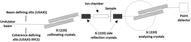
Schematic of the USAXS and USAXS-XPCS configurations at the APS USAXS instrument. Both configurations make use of the same set of Si (220) optics consisting of both vertical and horizontal collimating and analyzing crystal pairs. We used four reflections off horizontal crystal pairs and two reflections off vertical crystal pairs. The main difference resides in the pre-optics slits. In the case of USAXS, the slits define the beam while for USAXS-XPCS, the slits serve as a secondary coherent source which provides the partially coherent illumination as received by the sample.
For USAXS and subsequent ultra-small angle X-ray scattering – X-ray photon correlation spectroscopy (USAXS-XPCS) measurements, we cut a piece of sample from the sample disk. The sample dimension was approximately 1 mm × 1mm × 10 mm. We placed this cut sample inside a glass capillary with an outer diameter of 1.5 mm. We also filled the capillary with HCl + H2O solution of chosen strength while establishing that the sample was fully submerged inside the acid. We sealed the filled capillary with wax and placed it vertically in the beam. We further aligned the X-ray beam at the center of the sample for our scattering measurements.
2.2.2 USAXS-XPCS measurements
We conducted the USAXS-XPCS measurements with the USAXS instrument at the APS. The instrumental configuration for this type of coherent scattering experiment was described previously [44]. Most notably, as illustrated in Figure 1, we placed a pair of 15 μm × 15 μm coherence-defining slits in front of the collimating crystals as a secondary coherent source. Samples were loaded into the capillaries as described above. We followed an established procedure to monitor the nonequilibrium dynamics of samples using a scan mode of USAXS-XPCS, which is detailed in Supplementary Materials.
2.2.3 X-ray diffraction
The X-ray diffraction (XRD) measurements of the composites were made using an X-ray diffractometer (D8, Bruker, Woodlands, TX, USA).utilizing Cu Kα radiation (X-ray energy = 8.047 keV, wavelength = 1.541 Å) and incorporating a 2D position-sensitive multiwire detector (Hi-Star, Bruker, Woodlands, TX, USA). Zr-modified ACP/polymer resin composite samples, in the form of thin disks, approximately 1 mm thick and 10 mm in diameter, were soaked for a specified time in a selected HCl acid molar concentration, rinsed with water and dried, mounted and held on a glass slide by vacuum on the D8 vertical sample stage. Measurements were made in a reflection geometry optimized for a mean position sensitive detector (PSD) scattering angle, 2θ = 42.5°, and with the normal to the sample plane bisecting this angle. The PSD collected data over the scattering angle range: 25° < 2θ < 60° (q = 3.45 Å−1 to 7.06 Å−1) over a 1 h count time for each sample run. The incident slit collimation was a 1 mm pinhole, and each sample was oscillated by ± 2 mm within its own plane (perpendicular to q) in both the horizontal and vertical directions to ensure a statistically-representative volume was sampled during each XRD measurement.
The XRD measurements of powder ACP samples were made using a Siemens D500 X-ray diffractometer equipped with a Johansson monochromator that eliminates the Kα2 component of the Cu Kα radiation. We set the incident slit size at 0.68° and the receiving slit size at 0.15°. For both the pure ACP and Zr-modified ACP powders, 1 mL of 0.10 M HCl was added to (50 ± 1) mg of powder and the mixture was left overnight to react. We chose the duration of this reaction to be similar to the time span of the XPCS measurements. The acid was syphoned off, and the residue was dried at 100° C overnight. The fractional mass loss caused by this processing was similar (0.28 for pure ACP and 0.25 for Zr-ACP). The resulting powder was compacted into disk-shaped sample cells. XRD measurements were conducted over the scattering angle range of 20° < 2θ < 70° (q = 1.42 Å−1 to 4.68 Å−1) with a fixed step size of 0.025°, over a 1 h count time for each sample run. In addition, semi-quantitative energy dispersive spectroscopy (EDS) was carried out on the treated powders.
3. Results
We corrected the USAXS data with the intensity scattering profile of capillaries filled with HCl whose acidic strength was identical to that of the samples, as well as detector backgrounds. Such normalization placed the reduced USAXS data on an absolute scattering intensity scale [43, 45] and allowed differential scattering cross-sections to be extracted.
We applied a maximum entropy (MaxEnt) size distribution analysis method to the reduced 2D-collimated USAXS data. We conducted this analysis with the Irena SAS analysis package [46]. Here, we note that the MaxEnt method does not make a priori assumptions about the character of the particle size distribution. We do assume, however, that the ACP particles are spherical in shape, as suggested in previous work [15, 47]. This shape information contributes to the scattering form factors of the particles. The calculated scattering length (X-ray form-factor) densities of the fillers and the matrix are shown in Table 2, along with the scattering contrast factors used in the MaxEnt analysis. To assess the uncertainty of the results, we varied the intensity data by adding Gaussian noise that was scaled to the original intensity uncertainty, producing 10 datasets for statistical analysis. USAXS data and analysis results are shown in Figure 2. Based on the statistics of the results, we found that the diameters of the filler particles have a bimodal size distribution, with centers of distributions located at ≈ 1000 Å and ≈ 3200 Å. We attribute the first, smaller population to the primary particles and the second, larger population to the aggregation of the primary particles. These results are consistent with the findings of a wide range of in vivo and in vitro ACP studies [12, 16, 17, 47, 48]. Additionally, with assistance from the contrast parameters in Table 2, we found that the total scattering volume fraction of the ACP was about 0.26 ± 0.04, which yields a mass fraction of ACP at 0.37 ± 0.04. This result agrees with the nominal 0.4 mass fraction of ACP incorporated with the composites during synthesis, which suggests that the fillers and the resin matrix were indeed well mixed.
Table 2.
X-ray scattering length densities of ACP fillers and the polymer resin matrix
| Density (g cm−3) | Scattering length density (1014 m−2) | Contrast against 50BisGMA: 50TEGDMA (1028 m−4) | |
|---|---|---|---|
| ACP | 2.04 | 17.40 | 42.38 |
| BisGMA | 1.20 | 10.89 | 0 |
| TEGDMA | 1.20 | 10.90 | 0 |
Figure 2.

USAXS profile of ACP composite. The intensity is placed on the absolute intensity scale. In this and following figures, the vertical bars at each data point represent computed or estimated standard deviation uncertainties. The inset shows the volume size distribution of the ACP filler particles. The standard deviation uncertainties (vertical bars) on the volume size distribution were derived from 10 MaxEnt analyses of the USAXS data.
We have previously established that for this type of ACP filled dental composite bulk characterization methods are not adequately sensitive to detect the local and subtle structural changes in the amorphous fillers [48]. XPCS, on the other hand, is an interferometric technique based on monochromatic coherent X-rays. The coherent interference of short-wavelength X-rays gives rise to a so-called speckle pattern, which is directly related to the exact 3-D arrangement of electron density within the illuminated volume. [49] This leads to the unparalleled sensitivity of coherent X-ray scattering and diffraction techniques [50], including USAXS-XPCS [44, 51]. Taking advantage of this coherent interference effect, we were able to use USAXS-XPCS as a local structural probe to establish the correlation between water loss and initial structural change in the ACP composites under several heating conditions. Combining XPCS with XRD, we determined that crystallization did not occur during this initial period and structural change is related to the local structural reorganization in the amorphous materials. For the controlled experiments reported in this article, we again employed this USAXS based XPCS technique to examine the relationship between the time scale of local structure change and the acid concentration.
The data reduction and analysis procedure of USAXS-XPCS scans were previously reported [44, 52], and are included in the Supplementary Materials of this manuscript. In essence, we take advantage of the correlation coefficient ϕ(i,j), a statistical parameter that describes the degree of resemblance between two datasets, to analyze the correlation behavior in all sets of the USAXS-XPCS data.
Based on a 2D map of the correlation coefficient, we extract the underlying time scale of the local structural change using methods established elsewhere.[44, 48] These maps, shown in Figure 3, were analyzed with data acquired at HCl concentrations of 0.07 M, 0.10 M, 0.25 M, and 0.75 M, respectively. The corresponding pH values of the HCl are 1.15, 1, 0.60, and 0.13, respectively. The durations of these measurements range from slightly over an hour to more than 13 h.
Figure 3.

Correlation coefficient maps for ACP composites with HCl concentration at (a) 0.07 M, (b) 0.10 M, (c) 0.25 M, and (d) 0.75 M, respectively.
Following the data analysis procedure mentioned above, we extracted the time scales for the samples to reach a microstructurally stable state as a function of HCl concentration. The relationship between the time scale and the HCl concentration is displayed in Figure 4. It is clear that the measured time scale is inversely related to the HCl concentration, i.e., the rate of structural reorganization is strongly dependent on the acidic strength. A closer examination of the relationship between time scales and the HCl concentration leads to the inset of Figure 4. This approximately linear behavior suggests a power law relationship and a least-squares fitting gives this equation, T = 4.10 × c−0.90 ± 0.07, where T refers to the time scale and c is the HCl concentration. We will discuss the implication of this relationship later in this article.
Figure 4.
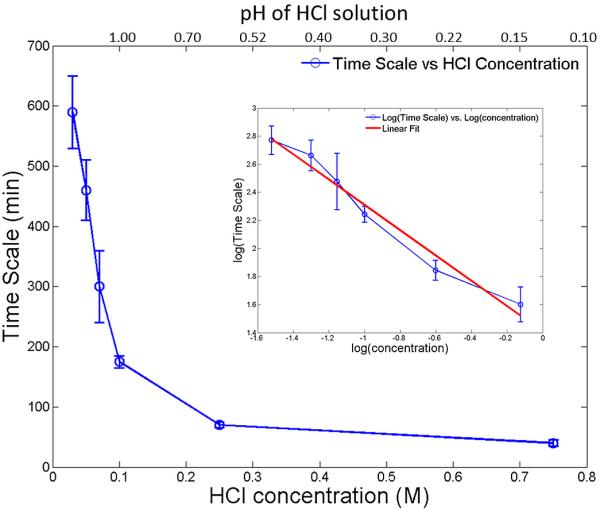
Dynamic time scales for structural change in the ACP composites as a function of the HCl solution concentrations (as well as pH values) in which the ACP composite samples were immersed. The inset shows that the logarithmic of the time scale is linearly related to the logarithmic of the concentration of the HCl solution.
The area detector XRD studies were carried out to investigate the time dependence for the emergence of the crystalline phase associated with ACP-to-apatite conversion within the ACP/resin composite, as a function of the acid concentration. In order to correlate the time scale for the emergence of the crystalline phase with the changes measured by the USAXS-XPCS scanning technique, the same acid concentrations were used as in the USAXS-XPCS experiments (0.07 M, 010 M 0.25 M, and 0.75M HCl). However, while each of the USAXS-XPCS studies was made in situ with the composite sample immersed in the selected HCl acid concentration, this was not possible for the XRD measurements for two reasons. Firstly, the time scale for relevant XRD measurements extends out to several days from the time when the sample is first immersed in acid. Secondly, the XRD instrument geometry precludes any such arrangement, given the need for a well-defined sample geometry with respect to the X-ray beam. Thus, for each acid concentration, measurements were made ex situ on a series of samples that had been immersed in the given HCl acid concentration for times ranging from 30 min to several days.
Additionally, other XRD measurements of composite samples were made in order to evaluate the degree to which the acid, itself, affects ACP-to-apatite conversion within the composites. Composite specimens were removed from acid after various immersion times and immersed in water for an extended period to determine the effect on ACP conversion, when compared to samples immersed only in water for extended times. Conversely, composites were removed from water after various immersion times, and then immersed in acid to determine how the transformation process is affected. Finally, a series of composite samples immersed in HCl for various times were studied where the ACP was not Zr-modified, to determine how Zr-modification affects conversion. These results will help the quantification of the phase conversion between the amorphous materials to their corresponding crystalline phases. We note that the XRD peaks for the composite materials after conversion were broad in general, which strongly suggests that the crystallinity of the converted materials was poor, i.e. the sizes of the crystallites were small.
As a further aid to this investigation, we measured several ACP and apatite powders by powder XRD, some of which had been subjected to acid and/or water immersion. The XRD patterns and changes in them could then be compared with the broad diffraction peaks seen for the composites with the area detector.
The area detector XRD data were sector-averaged to provide a 1D diffraction pattern of each composite sample. For analysis, the “control” XRD pattern obtained for a composite sample kept dry (hence no ACP conversion to crystalline phase), was subtracted from each composite pattern. The peak intensities integrated across the peaks of interest were used as a measure of the amount of amorphous-to-crystalline conversion within each sample.
Figures 5a and 5b show the sector-averaged data for the complete sequence of composite samples immersed for various times in 0.25 M HCl. Clearly, the overall scattering intensity increases with acid immersion time across all of the measured scattering angle range. It is likely that some of this may be due to ingress of Cl− ions into the composite during the acid immersion, where a connected porosity pathway is suggested based on TGA measurements of the same composites [48]. What is also observed is a progressive emergence of 3 broad peaks in the diffraction pattern. The integrated intensity within each peak is determined with an average, interpolated background count subtracted out. This subtraction is used to separate the increase in diffraction peak intensity from the general rise in scattering with acid immersion time. While the central feature in the XRD pattern has the greatest integrated intensity, this feature appears to be complicated by effects in the polymer resin and a general rise in intensity, likely associated with diffusion of Cl− ions into the composite resin. The main measure of the diffracted intensity was simply the sum of the integrated intensities in the first and third diffracted peaks observed. This is plotted in Figure 6 as a function of sample acid immersion time, and compared with corresponding in situ studies of the USAXS-XPCS correlation coefficient versus time. The above procedures were repeated for the four acid concentrations used for the in situ USAXS/XPCS measurements. Figure 6 shows the increase in integrated XRD peak intensity, based on 1 h counting times versus HCl immersion time for the four acid concentrations used. The time scales over which speckles are seen to change in the in situ USAXS-XPCS measurements are also indicated. It is immediately clear that, in every case, the operative time scale for changing USAXS-XPCS speckle patterns occurs mainly prior to the emergence of the diffraction peaks in the XRD studies.
Figure 5.

Sequence of XRD diffraction patterns for samples immersed for various times in 0.25 M HCl. (a) Early immersion times; (b) Later times. Vertical lines define the 1st and 3rd broad diffraction peaks over which intensity is integrated after an average background subtraction. Vertical bars at each data point indicate standard measurement uncertainties.
Figure 6.

Integrated peak intensities for the 1st and 3rd diffraction peak, and their sum, versus HCl immersion time in (a) 0.07 M HCl; (b) 0.10 M HCl; (c) 0.25 M HCl; and (d) 0.75 M HCl. Vertical bars indicate counting standard uncertainties, but data point scatter indicates greater stochastic uncertainties of HCl immersion and sample non-uniformity.
As Figure 6 shows, the non-equilibrium dynamics measured by USAXS-XPCS consistently precedes the onset and growth of crystalline structure within these dental composites. Here, the XPCS changing times correspond to the dynamic time scales shown in Figure 4. According to the literature [20, 53], it is known that a series of amorphous–to–amorphous phase transformations occur in the ACP/resin composite, in the presence of H2O but actually progressively removing H2O from the solid structure. Since removal of H2O is expected to densify the ACP particles [54], we surmise that the particle densification is the underlying cause of the non-equilibrium dynamics observed by USAXS-XPCS. We note that in a closely related study where H2O was removed through heating at temperatures above the boiling point of H2O under ambient pressure, very similar nonequilibrium behavior was observed [48]. In that study, it was found that loss of water is directly correlated with the dynamical microstructural change. Yet a comparison between the XRD intensity profiles before and after heating showed no change in atomic structure. In other words, loss of water in ACP precedes its transformation towards crystalline phases [6, 55]. Eventually, when the particles have lost sufficient water, an amorphous-to-crystalline phase transformation can occur, converting the last in the sequence of amorphous phases to apatite. This last transformation presents so little a density change that very small or no non-equilibrium dynamics (changing speckles) are observed from this point on by USAXS-XPCS. However, since apatite is crystalline, we do expect the XRD peak intensity to increase progressively as the amorphous–to– crystalline conversion proceeds.
The conversion of ACP to HAP takes place in H2O over an extended period, from several days to many weeks/months. Obviously, this time scale is too extended for practical in situ USAXS-XPCS measurements; such extended beam time is not available, and the changes in the XPCS speckles take place too slowly for the USAXS-XPCS scanning method to measure non-equilibrium dynamics to work reliably. In other words, the reaction rate is increased by immersing the samples in an acidic aqueous environment, which has the effect of significantly increasing the rate at which H2O is extracted from the ACP solid structure, hence accelerating the sequence of amorphous transformations that effectively dehydrate and densify successive solid particle phases within the polymer composite. While dilute HCl has been used in our measurements, other acids (e.g. lactic, citric) may be relevant for dental applications. It has been previously established that HAP is soluble in acids with a strong pH dependence on the solubility at low pH [56]. Therefore, it is relevant to consider the nature of the crystalline phase produced here, how it relates to HAP, and whether ACP-to-apatite conversion is affected in any other way than by catalysis. In this connection, we note that the XRD peaks in Figure 5 are broad and weak. This suggests that the amorphous-to-crystalline transformation results in poor (perhaps partial) crystallinity involving nanoscale crystallites [54]. Several additional XRD measurements were carried out to investigate the situation further.
Figure 7 compares the XRD pattern of ACP–to–HAP conversion in H2O to both the HAP reference powder and the powder obtained after post-conversion immersion in 0.07 M HCl acid (the most dilute used in XRD work). Figure 7a indicates that purely aqueous conversion of ACP in the composite to apatite (over 6 months) results in diffraction peaks at the same scattering angles as found for a standard HAP reference powder. (For accurate comparison, no control data for an unconverted ACP composite have been subtracted out.) This solution-mediated conversion was previously observed in ACP, and was found to be a function of only the pH of the mediating solution at constant temperature [4, 57]. This study established that this transition also occurs in ACP composites, although with a much longer transitional time scale (hours versus months).
Figure 7.

(a) Comparison of XRD patterns for ACP composite immersed for 6 months in H2O and HAP reference powder. For convenient comparison, no subtraction of data from a control unconverted composite has been made. (b) Comparison of XRD patterns for ACP composite converted to HAP in H2O, and the same composite subsequently immersed in 0.07 M HCl for 24 h.
Clearly, the HAP XRD peaks do not occur in the same places as the broad peaks that emerge (between the vertical lines) on conversion of ACP composites in HCl, shown in Figure 5. However, as Figure 7b shows, these “HAP” XRD peaks completely disappear after just 24 h immersion of the composite in dilute HCl. The HAP XRD peaks are replaced by a pattern with a similar overall shape to that for the composites immersed in HCl, but with only a hint of the XRD peak structure observed above for ACP composite conversion in HCl. We conclude that true HAP is highly soluble in dilute HCl, including that formed within a composite, when there is fluid access from the surface.
Figure 8 shows the effects of immersing the composite samples in H2O after various immersion times in 0.07 M HCl. These results reveal that conversion to true HAP depends on how far the conversion process has previously progressed in acid. For limited immersion time in acid, significant HAP XRD peaks develop. However, as the immersion time in acid is increased, so the capacity for true HAP conversion in H2O diminishes. For extended immersion times in dilute HCl that significantly exceed the time during which changing USAXS-XPCS speckles are observed, the characteristic XRD pattern for conversion in acid prevails. This pattern is not affected by subsequent extended immersion of the sample in H2O. We surmise that while HCl promotes the amorphous–to–amorphous sequence of changes, starting with ACP, the product of the final amorphous–to–crystalline conversion, HAP, is dissolved in HCl as it is formed. What remains is an insoluble acid mediated phase. Dissolution studies of Zr-modified and unmodified ACP powders in dilute HCl suggest that Zr-modified ACP (used in the composites here) is significantly less soluble in HCl than is the unmodified form of ACP. Certainly, XRD measurements of unmodified ACP composites immersed in 0.1 M HCl reveal a pattern similar to that for Zr-modified ACP composites, but with even less prominent diffraction peaks (Supplementary Materials). This observation is consistent with the conversion product in the Zr-modified case being less inclined to convert to HAP than that for the unmodified case due to ions specifically blocking potential sites for HAP nucleation and growth [40]. Also apparent is that the presence of heavy element Zr increases the XRD intensity of the Zr-modified ACP composites.
Figure 8.

XRD patterns of ACP composites immersed in 0.07 M HCl for various times, then transferred to H2O for 3 months
To explore this point further XRD studies were made of Zr-modified and unmodified ACP powders subjected to HCl acid immersion, as detailed in the Characterization Method section. Figure 9 shows the XRD spectra of Zr-modified ACP and unmodified ACP powders after the previously described HCl treatment. We found that these XRD patterns show strong similarities throughout the 2θ range, particularly at 2θ angles above 45°. The peaks common to both patterns are broad with full widths at half maximum intensity (FWHM) of ≈ 0.5°, strongly suggestive of poor crystallinity for the predicted HAP phase (stick pattern in (a)). The unmodified ACP sample after HCl immersion also features a number of extra peaks which are all considerably sharper (FWHM ≈ 0.17°). While the broad peaks are all well fit by the PDF file that describes HAP in the formula of Ca5(PO4)3(OH), the additional sharp peaks from the unmodified ACP powder are very well fit by monetite, which has a formula of CaHPO4. The sharpness of such lines also indicates that the grain size of the monetite is considerably larger than for the HAP present. These findings show that the Zr modification, while slowing the ACP-HAP conversion, does not contribute to the final chemical state of the HAP. In other words, the kinetically stable HAP phase is the destination of the ACP with or without the presence of Zr modification, which is further demonstrated by a series of FTIR measurements (Supplementary Materials) that show 1. Treatment in water or dilute HCl solutions leads Zr modified ACP powders to the formation of HAP; 2. HCl promotes the conversion from ACP to HAP for Zr modified powders.
Figure 9.

XRD patterns of (a) Zr-modified ACP powders and (b) unmodified ACP powders after a 0.1 M HCl treatment, together with predicted HAP stick pattern shown for (a), and predicted monetite stick pattern shown for (b). While broad peaks, roughly corresponding to the predicted HAP phase are present in both (a) and (b), narrow diffractions peaks corresponding to monetite are present only in (b).
4. Discussion
We have conducted a structural study of the static and dynamic structures of the ACP composites under controlled conditions of various degrees of acidic challenge. The static structural investigation was performed with conventional ex situ XRD, and the dynamic investigation was conducted with in situ USAXS-XPCS, which is a high-sensitivity interferometric local structure probe based on coherent interference of short wavelength, partially coherent X-rays.
Owing to the sensitivity to local structural changes provided by USAXS-XPCS, for this class of ACP-resin composite dental materials, we identified a two-step process that controls the structural variation. In the first step, the dental materials remain amorphous. However, we presented strong evidence for local structure changes in the length scale between approximately 100 nm and several μm. We found that the time scale for this type of local structure change strongly depends on the concentration of the acid in which the sample was immersed -- the higher the acid concentration, the shorter the dynamic time scale, i.e., the amorphous conversion was aided by the presence of acid. This dependence is analogous to the one that was previously identified for ACP powders during their conversions to HAP in various pH solutions [4], albeit that the time scales for ACP composites are significantly longer due to the presence of both polymer resin and Zr dopants. We have previously linked this amorphous conversion to the loss of water in ACPs, and identified an activation energy of (54.34 ± 10.90) kJ mol−1 [48]. We allude to the structure change with the densification of the ACP particles accompanying the loss of water. We also note that this activation energy was similar to that found for the change in sub-micrometer grain size in the ACPs [54].
To fulfill the potential offered by this type of dental material, it is critical that the release of the calcium and phosphate ions that accompanies the conversion between ACP and HAP be a slow and gradual process [40]. In this work, we identified an empirical relationship between the acid concentration and the time scale in the initial stage of this transition T = 4.10 × c−0.90. Following this empirical relationship, we draw the following conclusion: alluding to the much lower acidic concentration in the mouth, on average, this would imply that many months would be required for this conversion to complete under physiological oral conditions. Therefore, we suggest that this slow conversion enabled by both the resin matrix and the Zr modification is beneficial to gradual self-repairing of dental structures. However, highly acidic conditions, as shown by our data, can significantly accelerate this process and make the application of this class of materials less than optimal, while having a significant adverse effect in corroding the enamel [39]. Such conditions ought to be avoided as shown by our data.
We acquired information regarding the second step of this conversion process via ex situ XRD measurements where we found ACP undergoes a slow conversion to its crystalline phases. This conversion, however, does not start until the coherent speckle variation observed by USAXS-XPCS comes to a stop. This implies that during this step, variations in both density and grain size are limited. We found that emerged XRD crystalline peaks are weak and broad. This result shows that the crystallinity is poor, which is in agreement with previous findings about nanocrystallinity of such materials.[18, 58, 59]. These results also show that the resin and Zr modification significantly impede the conversion between Zr-modified ACP and HAP, even under conditions highly favorable to H2O removal and its subsequent phase transition [4].
By adjusting the immersion time of the ACP composite in acid, we found that as the immersion time in acid increases the capacity for true HAP conversion in H2O diminishes. This suggests that acid-aided dissolution of HAP occurs at the same time as hydroxyapatite is forming from ACP. Due to the poor crystallinity of these materials and the weakness and broadness of the diffraction peaks, we cannot fingerprint the phase and structure of the remainder material. We speculate that it was an insoluble acid mediated phase.
For the first time, we were able to follow the complete transition process from ACP to HAP in this class of dental composites in a controlled environment. The two-step process, which was speculated previously, was conclusively identified. We note that by no means was this set of findings complete. Notably, we were unable to pinpoint the crystalline phases of the converted materials due to the poor crystallinity of the materials. However, we were able to clarify the role of both acid and water in this solution-mediated, pH-dependent transition. Hopefully, the findings of this study will lead to a better understanding of the still largely unknown transformation from ACP to apatite in ACP-based composite materials, and the associated kinetics , especially for transformation in materials that have real-life implications.
5. Conclusion
Using in situ XPCS and ex situ XRD, we identified a two-step process that controls the acid-mediated structure conversion in ACP based dental composites, with the first step being an amorphous transformation and second being a slow transformation from amorphous to crystalline phases.
In the first step of conversion, we found its time scale T strongly depends on the acidic concentration c following T = 4.10 × c 0.90 ± 0.07.
We found the crystallinity of the crystallites formed in the second step of conversion being poor. We also showed that the resin and Zr modification significantly deter the crystalline conversion.
Supplementary Material
Acknowledgments
Use of the Advanced Photon Source, an Office of Science User Facility operated for the U.S. Department of Energy (DOE) Office of Science by Argonne National Laboratory, was supported by the U.S. DOE under Contract No. DE-AC02-06CH11357. ChemMatCARS Sector 15 is principally supported by the National Science Foundation/Department of Energy under grant number NSF/CHE-0822838. Use of the Advanced Photon Source was supported by the U. S. Department of Energy, Office of Science, Office of Basic Energy Sciences, under Contract No. DE-AC02-06CH11357. This reported work was also supported by the National Institute of Dental and Craniofacial Research (NIDCR grant DE 13169) and the American Dental Association Foundation. Donation of monomers by Esstech, Essington, PA, is gratefully acknowledged.
Footnotes
Publisher's Disclaimer: This is a PDF file of an unedited manuscript that has been accepted for publication. As a service to our customers we are providing this early version of the manuscript. The manuscript will undergo copyediting, typesetting, and review of the resulting proof before it is published in its final citable form. Please note that during the production process errors may be discovered which could affect the content, and all legal disclaimers that apply to the journal pertain.
Certain commercial materials and equipment are identified in this paper only to specify adequately the experimental procedure. In no case does such identification imply recommendation by NIST nor does it imply that the material or equipment identified is necessarily the best available for this purpose.
References
- 1.Eanes ED. Amorphous calcium phosphate: thermodynamic and kinetic considerations. In: Amjad Z, editor. Calcium phosphates in biological and industrial systems. Kluwer Academic; Dordrecht: 1998. pp. 21–39. [Google Scholar]
- 2.Abbona F, Madsen HEL, Boistelle R. The initial phases of calcium and magnesium phosphates precipitated from solutions of high to medium concentrations. J Cryst Growth. 1986;74:581–90. [Google Scholar]
- 3.van Kemenade MJJM, de Bruyn PL. A kinetic study of precipitation from supersaturated calcium phosphate solutions. J Colloid Interface Sci. 1987;118:564–85. [Google Scholar]
- 4.Boskey AL, Posner AS. Conversion of Amorphous Calcium Phosphate to Microcrystalline Hydroxyapatite - Ph-Dependent, Solution-Mediated, Solid-Solid Conversion. J Phys Chem. 1973;77:2313–7. [Google Scholar]
- 5.Harries JE, Hukins DWL, Holt C, Hasnain SS. Conversion of Amorphous Calcium-Phosphate into Hydroxyapatite Investigated by Exafs Spectroscopy. J Cryst Growth. 1987;84:563–70. [Google Scholar]
- 6.Feng CF, Khor KA, Kweh SWK, Cheang P. Thermally induced crystallization of amorphous calcium phosphate in plasma-spheroidised hydroxyapatite powders. Mater Lett. 2000;46:229–33. [Google Scholar]
- 7.Eanes ED, Gillesse IH, Posner AS. INTERMEDIATE STATES IN PRECIPITATION OF HYDROXYAPATITE. Nature. 1965;208:365–&. doi: 10.1038/208365a0. [DOI] [PubMed] [Google Scholar]
- 8.Betts F, Blumenthal NC, Posner AS, Becker GL, Lehninger AL. ATOMIC-STRUCTURE OF INTRACELLULAR AMORPHOUS CALCIUM-PHOSPHATE DEPOSITS. PNAS. 1975;72:2088–90. doi: 10.1073/pnas.72.6.2088. [DOI] [PMC free article] [PubMed] [Google Scholar]
- 9.Posner AS, Betts F, Blumenthal NC. FORMATION AND STRUCTURE OF SYNTHETIC AND BONE HYDROXYAPATITES. Prog Cryst Growth Charact Mater. 1980;3:49–64. [Google Scholar]
- 10.Beniash E, Aizenberg J, Addadi L, Weiner S. Amorphous calcium carbonate transforms into calcite during sea urchin larval spicule growth. Proceedings of the Royal Society of London Series B-Biological Sciences. 1997;264:461–5. [Google Scholar]
- 11.Politi Y, Arad T, Klein E, Weiner S, Addadi L. Sea urchin spine calcite forms via a transient amorphous calcium carbonate phase. Science. 2004;306:1161–4. doi: 10.1126/science.1102289. [DOI] [PubMed] [Google Scholar]
- 12.Lowenstam HA, Weiner S. Transformation of Amorphous Calcium-Phosphate to Crystalline Dahllite in the Radular Teeth of Chitons. Science. 1985;227:51–3. doi: 10.1126/science.227.4682.51. [DOI] [PubMed] [Google Scholar]
- 13.Weiss IM, Tuross N, Addadi L, Weiner S. Mollusc larval shell formation: Amorphous calcium carbonate is a precursor phase for aragonite. J Exp Zool. 2002;293:478–91. doi: 10.1002/jez.90004. [DOI] [PubMed] [Google Scholar]
- 14.Dillaman R, Hequembourg S, Gay M. Early pattern of calcification in the dorsal carapace of the blue crab, Callinectes sapidus. J Morphol. 2005;263:356–74. doi: 10.1002/jmor.10311. [DOI] [PubMed] [Google Scholar]
- 15.Mahamid J, Sharir A, Addadi L, Weiner S. Amorphous calcium phosphate is a major component of the forming fin bones of zebrafish: Indications for an amorphous precursor phase. PNAS. 2008;105:12748–53. doi: 10.1073/pnas.0803354105. [DOI] [PMC free article] [PubMed] [Google Scholar]
- 16.Mahamid J, Aichmayer B, Shimoni E, Ziblat R, Li CH, Siegel S, Paris O, Fratzl P, Weiner S, Addadi L. Mapping amorphous calcium phosphate transformation into crystalline mineral from the cell to the bone in zebrafish fin rays. PNAS. 2010;107:6316–21. doi: 10.1073/pnas.0914218107. [DOI] [PMC free article] [PubMed] [Google Scholar]
- 17.Beniash E, Metzler RA, Lam RSK, Gilbert P. Transient amorphous calcium phosphate in forming enamel. J Struct Biol. 2009;166:133–43. doi: 10.1016/j.jsb.2009.02.001. [DOI] [PMC free article] [PubMed] [Google Scholar]
- 18.He G, Dahl T, Veis A, George A. Nucleation of apatite crystals in vitro by self-assembled dentin matrix protein, 1. Nat Mater. 2003;2:552–8. doi: 10.1038/nmat945. [DOI] [PubMed] [Google Scholar]
- 19.Tsuji T, Onuma K, Yamamoto A, Iijima M, Shiba K. Direct transformation from amorphous to crystalline calcium phosphate facilitated by motif-programmed artificial proteins. PNAS. 2008;105:16866–70. doi: 10.1073/pnas.0804277105. [DOI] [PMC free article] [PubMed] [Google Scholar]
- 20.Palmer LC, Newcomb CJ, Kaltz SR, Spoerke ED, Stupp SI. Biomimetic Systems for Hydroxyapatite Mineralization Inspired By Bone and Enamel. Chem Rev. 2008;108:4754–83. doi: 10.1021/cr8004422. [DOI] [PMC free article] [PubMed] [Google Scholar]
- 21.Combes C, Rey C. Amorphous calcium phosphates: Synthesis, properties and uses in biomaterials. Acta Biomater. 2010;6:3362–78. doi: 10.1016/j.actbio.2010.02.017. [DOI] [PubMed] [Google Scholar]
- 22.Dorozhkin SV. Calcium orthophosphates. Journal of Materials Science. 2007;42:1061–95. [Google Scholar]
- 23.Dorozhkin SV. Amorphous calcium (ortho)phosphates. Acta Biomater. 2010;6:4457–75. doi: 10.1016/j.actbio.2010.06.031. [DOI] [PubMed] [Google Scholar]
- 24.Dorozhkin SV. Biphasic, triphasic and multiphasic calcium orthophosphates. Acta Biomater. 2012;8:963–77. doi: 10.1016/j.actbio.2011.09.003. [DOI] [PubMed] [Google Scholar]
- 25.Boskey AL. Amorphous calcium phosphate: The contention of bone. J Dent Res. 1997;76:1433–6. doi: 10.1177/00220345970760080501. [DOI] [PubMed] [Google Scholar]
- 26.Nagano M, Nakamura T, Kokubo T, Tanahashi M, Ogawa M. Differences of bone bonding ability and degradation behaviour in vivo between amorphous calcium phosphate and highly crystalline hydroxyapatite coating. Biomaterials. 1996;17:1771–7. doi: 10.1016/0142-9612(95)00357-6. [DOI] [PubMed] [Google Scholar]
- 27.Zhao J, Liu Y, Sun WB, Zhang H. Amorphous calcium phosphate and its application in dentistry. Chem Cent J. 2011;5:40. doi: 10.1186/1752-153X-5-40. [DOI] [PMC free article] [PubMed] [Google Scholar]
- 28.Skrtic D, Antonucci JM, Eanes ED. Amorphous calcium phosphate-based bioactive polymeric composites for mineralized tissue regeneration. J Res Nat Inst Stand Technol. 2003;108:167–82. doi: 10.6028/jres.108.017. [DOI] [PMC free article] [PubMed] [Google Scholar]
- 29.Skrtic D, Antonucci JM. Effect of bifunctional comonomers on mechanical strength and water sorption of amorphous calcium phosphate- and silanized glass-filled Bis-GMA-based composites. Biomaterials. 2003;24:2881–8. doi: 10.1016/s0142-9612(03)00119-4. [DOI] [PubMed] [Google Scholar]
- 30.Skrtic D, Antonucci JM, Eanes ED, Eldelman N. Dental composites based on hybrid and surface-modified amorphous calcium phosphates. Biomaterials. 2004;25:1141–50. doi: 10.1016/j.biomaterials.2003.08.001. [DOI] [PubMed] [Google Scholar]
- 31.Skrtic D, Stansbury JW, Antonucci JM. Volumetric contraction and methacrylate conversion in photo-polymerized amorphous calcium phosphate/methacrylate composites. Biomaterials. 2003;24:2443–9. doi: 10.1016/s0142-9612(02)00574-4. [DOI] [PubMed] [Google Scholar]
- 32.Skrtic D, Antonucci JM, Eanes ED, Eichmiller FC, Schumacher GE. Physicochemical evaluation of bioactive polymeric composites based on hybrid amorphous calcium phosphates. J Biomed Mater Res. 2000;53:381–91. doi: 10.1002/1097-4636(2000)53:4<381::aid-jbm12>3.0.co;2-h. [DOI] [PubMed] [Google Scholar]
- 33.Skrtic D, Hailer AW, Takagi S, Antonucci JM, Eanes ED. Quantitative assessment of the efficacy of amorphous calcium phosphate/methacrylate composites in remineralizing caries-like lesions artificially produced in bovine enamel. J Dent Res. 1996;75:1679–86. doi: 10.1177/00220345960750091001. [DOI] [PubMed] [Google Scholar]
- 34.Langhorst SE, O'Donnell JNR, Skrtic D. In vitro remineralization of enamel by polymeric amorphous calcium phosphate composite: Quantitative microradiographic study. Dent Mater. 2009;25:884–91. doi: 10.1016/j.dental.2009.01.094. [DOI] [PMC free article] [PubMed] [Google Scholar]
- 35.Antonucci JM, Skrtic D. Bioactive and biocompatible polymeric composites based on amorphous calcium phosphate. In: Ramalingam M, Tiwari A, Ramakrishna S, Kobayashi H, editors. Integrated Biomaterials for Medical Applications. Scrivener Publishing; Salem: 2012. pp. 67–119. [Google Scholar]
- 36.Llena C, Forner L, Baca P. Anticariogenicity of casein phosphopeptide-amorphous calcium phosphate: a review of the literature. J Contemp Dent Pract. 2009;10:1–9. [PubMed] [Google Scholar]
- 37.Olszta MJ, Cheng XG, Jee SS, Kumar R, Kim YY, Kaufman MJ, Douglas EP, Gower LB. Bone structure and formation: A new perspective. Materials Science & Engineering R-Reports. 2007;58:77–116. [Google Scholar]
- 38.Skrtic D, Antonucci JM. Bioactive Polymeric Composites for Tooth Mineral Regeneration: Physicochemical and Cellular Aspects. Journal of Functional Biomaterials. 2011;2:271–307. doi: 10.3390/jfb2030271. [DOI] [PMC free article] [PubMed] [Google Scholar]
- 39.Creanor S, Creanor S, Alharthy N. A comparison of in vitro erosion-like mineral loss between continuous and intermittent acidic exposure with and without human saliva. Arch Oral Biol. 2011;56:703–8. doi: 10.1016/j.archoralbio.2010.12.014. [DOI] [PubMed] [Google Scholar]
- 40.Skrtic D, Antonucci JM, Eanes ED, Brunworth RT. Silica- and zirconia-hybridized amorphous calcium phosphate: Effect on transformation to hydroxyapatite. J Biomed Mater Res. 2002;59:597–604. doi: 10.1002/jbm.10017. [DOI] [PubMed] [Google Scholar]
- 41.Lovell LG, Stansbury JW, Syrpes DC, Bowman CN. Effects of Composition and Reactivity on the Reaction Kinetics of Dimethacrylate/Dimethacrylate Copolymerizations. Macromolecules. 1999;32:3913–21. [Google Scholar]
- 42.Skrtic D, Antonucci JM, Eanes ED. Improved properties of amorphous calcium phosphate fillers in remineralizing resin composites. Dental Materials. 1996;12:295–301. doi: 10.1016/s0109-5641(96)80037-6. [DOI] [PubMed] [Google Scholar]
- 43.Ilavsky J, Jemian PR, Allen AJ, Zhang F, Levine LE, Long GG. Ultra-small-angle X-ray scattering at the Advanced Photon Source. J Appl Crystallogr. 2009;42:469–79. [Google Scholar]
- 44.Zhang F, Allen AJ, Levine LE, Ilavsky J, Long GG, Sandy AR. Development of Ultrasmall-Angle X-ray Scattering - X-ray Photon Correlation Spectroscopy. J Appl Crystallogr. 2011;44:200–12. [Google Scholar]
- 45.Zhang F, Ilavsky J, Long GG, Quintana JPG, Allen AJ, Jemian PR. Glassy Carbon as an Absolute Intensity Calibration Standard for Small-Angle Scattering. Metallurgical and Materials Transactions a-Physical Metallurgy and Materials Science. 2010;41A:1151–8. [Google Scholar]
- 46.Ilavsky J, Jemian PR. Irena: tool suite for modeling and analysis of small-angle scattering. J Appl Crystallogr. 2009;42:347–53. [Google Scholar]
- 47.Posner AS, Betts F. Synthetic Amorphous Calcium-Phosphate and Its Relation to Bone-Mineral Structure. Accounts of Chemical Research. 1975;8:273–81. [Google Scholar]
- 48.Zhang F, Allen AJ, Levine LE, Espinal L, Antonucci JM, Skrtic D, O'Donnell JNR, Ilavsky J. Ultra-small-angle X-ray scattering-X-ray photon correlation spectroscopy studies of incipient structural changes in amorphous calcium phosphate-based dental composites. Journal of Biomedical Materials Research Part A. 2012;100A:1293–306. doi: 10.1002/jbm.a.34018. [DOI] [PMC free article] [PubMed] [Google Scholar]
- 49.Miao JW, Charalambous P, Kirz J, Sayre D. Extending the methodology of X-ray crystallography to allow imaging of micrometre-sized non-crystalline specimens. Nature. 1999;400:342–4. [Google Scholar]
- 50.Nugent KA. Coherent methods in the X-ray sciences. Advances in Physics. 2010;59:1–99. [Google Scholar]
- 51.Ma L, Zhang F, Allen AJ, Levine LE. Unveiling the Origin of a Nonequilibrium Dynamic Process Detected by X-Ray Photon Correlation Spectroscopy via a Finite Element Analysis Approach. Acta Crystallographica Section A. 2014:70. doi: 10.1107/S205327331400686X. doi:10.1107/S205327331400686X. [DOI] [PubMed] [Google Scholar]
- 52.Zhang F, Allen AJ, Levine LE, Ilavsky J, Long GG. Ultra-Small-Angle X-ray Scattering-X-ray Photon Correlation Spectroscopy: A New Measurement Technique for In-Situ Studies of Equilibrium and Nonequilibrium Dynamics. Metallurgical and Materials Transactions a-Physical Metallurgy and Materials Science. 2012;43A:1445–53. [Google Scholar]
- 53.Wang L, Nancollas GH. Calcium orthophosphates: crystallization and dissolution. Chem Rev. 2008;108:4628–69. doi: 10.1021/cr0782574. [DOI] [PMC free article] [PubMed] [Google Scholar]
- 54.Layrolle P, Ito A, Tateishi T. Sol-gel synthesis of amorphous calcium phosphate and sintering into microporous hydroxyapatite bioceramics. J Am Ceram Soc. 1998;81:1421–8. [Google Scholar]
- 55.Luo ZS, Cui FZ, Li WZ. Low-temperature crystallization of calcium phosphate coatings synthesized by ion-beam-assisted deposition. J Biomed Mater Res. 1999;46:80–6. doi: 10.1002/(sici)1097-4636(199907)46:1<80::aid-jbm9>3.0.co;2-9. [DOI] [PubMed] [Google Scholar]
- 56.Chen ZF, Darvell BW, Leung VWH. Hydroxyapatite solubility in simple inorganic solutions. Arch Oral Biol. 2004;49:359–67. doi: 10.1016/j.archoralbio.2003.12.004. [DOI] [PubMed] [Google Scholar]
- 57.Liu C, Huang Y, Shen W, Cui J. Kinetics of hydroxyapatite precipitation at pH 10 to 11. Biomaterials. 2001;22:301–6. doi: 10.1016/s0142-9612(00)00166-6. [DOI] [PubMed] [Google Scholar]
- 58.Julien M, Khairoun I, LeGeros RZ, Delplace S, Pilet P, Weiss P, Daculsi G, Bouler JM, Guicheux J. Physico-chemical–mechanical and in vitro biological properties of calcium phosphate cements with doped amorphous calcium phosphates. Biomaterials. 2007;28:956–65. doi: 10.1016/j.biomaterials.2006.10.018. [DOI] [PubMed] [Google Scholar]
- 59.Wang X, Ye J, Wang Y, Wu X, Bai B. Control of crystallinity of hydrated products in a calcium phosphate bone cement. Journal of Biomedical Materials Research Part A. 2007;81A:781–90. doi: 10.1002/jbm.a.31059. [DOI] [PubMed] [Google Scholar]
Associated Data
This section collects any data citations, data availability statements, or supplementary materials included in this article.