Abstract
Breast cancer is the largest detected cancer amongst women in the US. In this work, our team reports on the development of piezoresistive microcantilevers (PMCs) to investigate their potential use in the accurate detection and characterization of benign and diseased breast tissues by performing indentations on the micro-scale tissue specimens. The PMCs used in these experiments have been fabricated using laboratory-made silicon-on-insulator (SOI) substrate, which significantly reduces the fabrication costs. The PMCs are 260 μm long, 35 μm wide and 2 μm thick with resistivity of order 1.316 X 10⁻³ Ω-cm obtained by using boron diffusion technique. For indenting the tissue, we utilized 8 μm thick cylindrical SU-8 tip. The PMC was calibrated against a known AFM probe. Breast tissue cores from seven different specimens were indented using PMC to identify benign and cancerous tissue cores. Furthermore, field emission scanning electron microscopy (FE-SEM) of benign and cancerous specimens showed marked differences in the tissue morphology, which further validates our observed experimental data with the PMCs. While these patient aspecific feasibility studies clearly demonstrate the ability to discriminate between benign and cancerous breast tissues, further investigation is necessary to perform automated mechano-phenotyping (classification) of breast cancer: from onset to disease progression.
Keywords: MEMS sensor, Piezoresistive Microcantilever, Breast Cancer, Tissue Microarray
1. Introduction
According to American Cancer Society, breast cancer continues to be the second leading cause of cancer-related female deaths in the USA, with 232,340 new cases and 39,620 estimated deaths (American Cancer Society, 2013). Future progress in several key areas of cancer research and drug discovery will rely upon the capacity of investigators to reliably detect, characterize and track subtle changes that occur in terms of biomarker and morphologic signatures in the tumor environment during the transformation from the benign to cancerous state. Early detection and treatment of breast cancer can not only prolong the life of the individual, but also lead to an improved quality of life. The importance of early cancer detection and accurate staging of disease for improved treatment has prompted considerable research interest in quantifying the state and progression of cancer. Mechanical phenotyping has been demonstrated as an effective quantitative biomarker for characterizing the state of malignancy in cells (Kim et al., 2009) and tissue (Roy et al., 2010). The conventional AFM technique was used to study nanomechanical properties associated inherent to metastatic adenocarcinoma cells obtained from body cavity fluid samples (Cross et al., 2007). The results revealed that for the similar shapes cells, the mechanical analysis can differentiate normal and cancer cells. Plodinec et al., 2012, studied the change in stiffness of the breast tissue with progression of cancer using AFM cantilever. (Suresh et al., 2007) published a detailed study on mechanistic discussions of the connections among alterations to subcellular structures, attendant changes in cell deformability, cytoadherence, migration, invasion and tumor metastasis, and various quantitative mechanical and physical assays to extract the elastic and viscoelastic deformability of cancer cells. A proteomics analyses was carried out to understand the role of tissue stiffness and stress on nucleoskeletal protein lamin-A (Swift et al., 2013). Advances in cancer biomechanics research has been supplemented by a surge in recent development of mechanical property measurement techniques at the micro-and nano-scale (Alessandrini and Facci, 2009). Capacitive force sensors have previously been reported as a reliable means for investigating cellular mechanics (Seonghwan et al., 2009). However, these methods have considerable microfabrication challenges. Silicon-on-insulator (SOI) wafers are typically employed for microfabrication of the capacitive sensors as the structure needs to be completely isolated between two electrodes (Sarajlic et al., 2004). The complete isolated structure is difficult to obtain as it is challenging to control the etching area. Moreover, the capacitive method requires complicated electronics for sensor readout. Another promising technique for characterizing tissue samples is Atomic Force Microscopy (AFM), which has already gained wide acceptance in quantifying the material properties of biomaterials (Roy et al., 2013). The AFM system consists of a microcantilever, which is piezoelectrically controlled to indent specimens. The microcantilever deflection is optically sensed, which is related to sample stiffness probed by the AFM (Alessandrini and Facci, 2009). While optical detection is highly accurate in measuring small displacements, it requires precise alignment of the optical system. Furthermore, the optical (laser) measurement of cantilever deflection (Gimzewski et al., 1994; Thundat et al., 1994; Mukhopadhyay et al., 2005; Ghatkesar et al., 2008; Backmann et al., 2005; Berger et al., 1997; Fritz et al., 2000; Lang et al., 1999) has several practical problems such as complex electronics, bulky optics, and inability to be used in opaque liquids. In addition, the AFM is also limited by its low throughput. Commercial AFMs typically use a single cantilever to probe discrete locations on the sample surface, which becomes cumbersome for large specimens such as histopathological tissue. Conventional AFM stages provide a limited range of travel, which necessitates the use of manual positioning systems to align the AFM probe and specimens. As such, piezoresistive sensing mechanisms offer an attractive alternative to the aforementioned techniques.
Piezoresistive sensors can be used in opaque liquids and do not require complex readout electronics. The design of piezoresistive sensors by changing the parameters like doping concentration, piezoresistor dimensions and using different manufacturing techniques for conventional diaphragm shapes, square, and circular shapes have been studied by several groups (Merlos et al., 2000; Bae et al., 2004; Pramanik et al., 2006). Piezoresistive sensors are widely employed as sensing elements in pressure sensor (Boisen et al., 2009; Gautsch et al., 2002; Hierlemann et al., 2000; Kanda et al., 1997), chemical sensors (Bae et al., 2004; Pramanik et al., 2006; Cho et al., 2008), force sensors (Yang et al., 2003) and stress sensors Loui et al., 2008). In addition, multiple piezoresistive cantilevers can be microfabricated in an array-format (Seonghwan et al., 2009), which considerably improves the sensing throughput and offers a cost-effective approach for quantifying biomaterial mechanical properties.
To our knowledge, there is no existing study utilizing piezoresistive microcantilever force sensors for detecting cancer progression in tissue. In this paper, we report on the fabrication and testing of MEMS-based piezoresistive microcantilevers with an SU-8 tip for detecting benign and cancerous breast tissue by indenting designated tissue regions inside breast tissue cores obtained from seven different specimens. In the Materials and Methods section, we discuss the steps involved in fabricating the microcantilever and the AFM experimental setup used to assess the sensor performance. In the Results and Discussion section, we discuss the sensitivity and performance of the sensor on breast tissue specimens which also include our future research goals in this area.
2. Experimental Work
2.1 AFM experimental setup
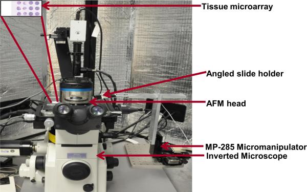
The AFM experimental setup used in this study is shown in Fig. 1. The AFM system is comprised of the AFM scanning head and the controller (MFP-3D-BIOTM, Asylum Research, Inc.) coupled to an inverted microscope (Model: TE2000U, Nikon, Inc.) such that the AFM head rests on the microscope. The whole setup is enclosed within an acoustic hood to isolate it from external noise. A CCD camera (QImaging Inc, Model: Retiga 2000R) is mounted to the microscope.
FIGURE 1.
AFM experimental setup integrated with piezoresistive sensor used for nanoindentation.
The range of the X and Y-axes of the piezoactuated stage is 90 μm and the customized range for the Z-axis is 40 μm. Situated at the base of the microscope is a motorized MP-285 micromanipulator (manufactured by Sutter Instruments, Novato, CA), to which is attached a custom-made end-effector. The fabricated microcantilever is attached to an angled slide holder mounted on the end effector. The MP-285 has a step resolution of 40 nm and a range of 2.54 cm along the X- and Y-axes. The micromanipulator, microscope and the AFM head are placed on a vibration isolation table (manufactured by Herzan) to eliminate base vibrations. A detailed explanation of AFM probe-sample interactions and tissue microarray preparation protocol is presented in our earlier work (Roy et al., 2010). The AFM setup was specifically used for measuring the spring constant of the fabricated cantilever. The XY stage of the AFM was used for holding the tissue slide, while the AFM microscope was used for imaging the piezoresistive sensor. It is possible to achieve the above without using the AFM setup by using an external microscope.
2.2 Sensor fabrication
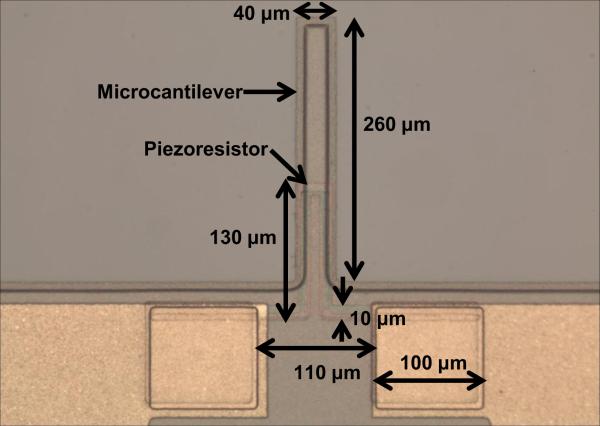
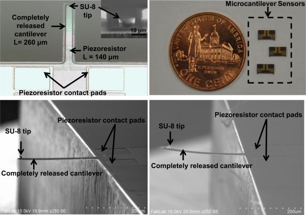
The sensor consists of an n-type cantilever on which p-type silicon piezoresistor is integrated. The cantilever is 260 μm long, 35 μm wide and 2 μm thick. Each cantilever has a built-in piezoresistor. The sensor is fabricated using standard silicon micro-machining technology and is reported in our earlier work (Pandya et al., 2014). The material used for fabricating microcantilever was polysilicon. Polysilicon film (2.0 μm thick) was grown using LPCVD (Low Pressure Chemical Vapor Deposition) on oxidized silicon wafer (4-inch diameter) to form silicon-on-insulator (SOI) substrate. Spin-on-dopants (SODs) B155 and B154 were used to dope the piezoresistor area (1.316 × 10⁻³ Ω-cm) and piezoresistor contacts (1.747 × 10⁻⁴ Ω-cm) respectively (Pandya et al., 2014). The optical photograph showing geometry of piezoresistive microcantilever without SU-8 tip is shown in Fig. 2. In the sensor fabrication process, 200 nm thick silicon nitride (Si3N4) plays an important role for compensating the stress in the device layer (Choudhry et al., 2007). Si3N4 also acts as a passivation layer even in a conductive solution like phosphate buffered saline (PBS), which is used for hydrating or preserving the tissues. The top view of a completely released piezoresistive microcantilever and sensor chips is shown in Fig. 3(a) and (b). The insert in Fig. 3(a) shows a close-up view of SU-8 tip. As patterning of SU-8 is easier compared to conventional Si tips, SU-8 was selected as the tip material. The tip diameter was chosen as 10 μm while the height of the SU-8 tip was 8 μm (Pandya et al., 2014).
FIGURE 2.
Optical photograph showing geometry of piezoresistive microcantilever without SU-8 tip.
FIGURE 3.
Photographs of (a) top-view of piezoresistive microcantilever (inset shows close-up view of SU-8 tip), (b) microcantilever sensor chips, (c) cross-sectional SEM image of piezoresistive microcantilever with 200 nm of Si3N4 as stress compensating layer, and (d) microcantilever without Si3N4 layer.
The scanning electron microscopy (SEM) images of the microcantilever with an SU-8 tip with and without 200 nm thick Si3N4 is shown in Fig. 3 (c) and Fig. 3(d) respectively.
2.3 Tissue microarray preparation and imaging
Normal breast is composed mainly of connective tissue and adipose tissue, whereas the breast lobules are small and underdeveloped except for during periods of lactation. When examining the changes in the mechanical characteristics of the breast tissue specimen during cancer progression, it is necessary to perform indentation on a well-defined sampling region. To enable accurate sampling of the identified region, we have used tissue microarray (TMA) technology. Institutional Review Board (IRB) has determined that the work done on this project does not meet the definition of human subject research.
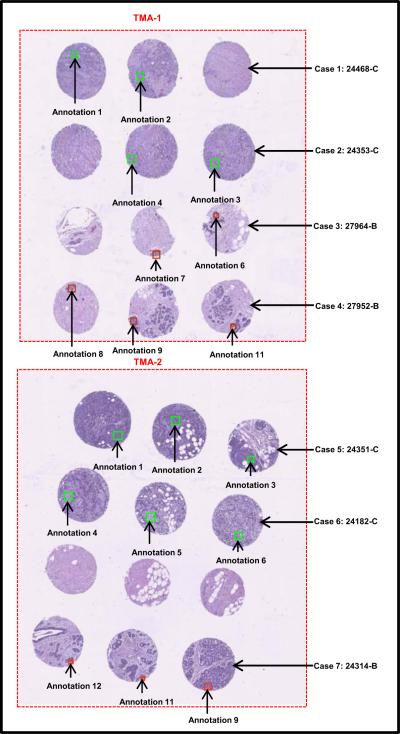
Benign and cancerous breast tissue blocks were carefully selected from archival tissue resources at the Histopathology and Imaging Core Facility at Rutgers Cancer Institute of New Jersey. These formalin-fixed paraffin-embedded (FFPE) tissue blocks were collected with patient consent and in compliance with approved protocols, from excess surgical material or tissue excised during autopsy, and can be preserved for an extended period of time for use in biomedical research and education. As a first attempt to investigate the mechanical properties of tissue with piezoresistive sensors, we chose cases of high-grade invasive ductal carcinoma of the breast as the cancer group. Specimens in the benign group originated from regions outside of tumor margin and presented benign breast morphology, as confirmed by a certified pathologist. Using specially designed needles, a skilled technician extracted three cylinder tissue cores of 0.6 mm in diameter from specified regions from each donor tissue block, and inserted the cores into recipient paraffin blocks using Manual Tissue Arrayer (Beecher Instruments) to form a tissue microarray (TMA). Consecutive slices of 4 μm thickness were sectioned from the finished TMAs and transferred onto glass slides. One slice from each TMA was histologically stained with hematoxylin and eosin (H&E) and imaged under 20X magnification using a Trestle MedMicroscopy whole-slide scanner. The whole slide images were hosted online with annotations on specific epithelial tissue regions to direct microsensor sampling (see Fig. 4).
FIGURE 4.
Optical image of breast TMAs containing 7 different cases (“C” stands for Cancer and “B” for Benign tissue core).
One case was eliminated from the experiment due to lack of sufficient epithelial tissue in all three cores; this sometimes occurs since epithelial tissue only occupies a relatively small portion of the total volume in normal breast architecture. A section adjacent to the above H&E slide was then deparaffinzed: Xylene (5 min, 3 times); 100% Alcohol (5 min, 2 times); 95% Alcohol (5 min, 1 time); 75% Alcohol (5 min, 1 time); rinsed in PBS (1-2 times) and immersed in PBS holding solution until MEMS assessment. With visual help of the whole slide TMA image, microcantilever probing was specifically targeted onto the locations corresponding to highlighted regions of the adjacent slide. The green and red block on the cores represents the annotated region of interest (ROI).
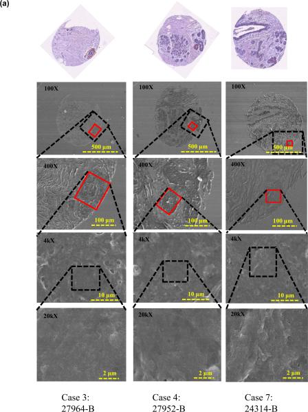
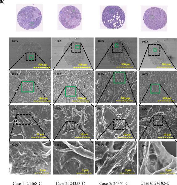
To further confirm tissue architecture and study nanostructure of the tissue regions under study, an additional tissue slice was deparaffinzed (protocol as above) and FE-SEM images of the breast tissue cores were acquired. Figure 5 shows the FE-SEM images of benign and cancerous tissue cores.
FIGURE 5.
FE-SEM images of breast tissue cores containing 7 different cases (a) Benign tissue core, and (b) Cancerous tissue core.
It was observed that the benign epithelial ROIs exhibits organized breast lobules and stroma structure and the subcellular views shows smoother texture, while in regions containing cancer, the tissues are uneven and display complicated rupturing-looking texture. The differences observed in microstructures as revealed by FE-SEM independently confirmed the findings that were obtained through mechanical measurements, which exhibited significant differences between the benign and diseased tissues states. We will discuss these differences in the following section.
3. Results and Discussion
3.1 Spring Constant Calibration
The spring constant of the fabricated microcantilever was measured using the reference cantilever method (Gates et al., 2011). In this method the spring constant of the unknown test cantilever is obtained by performing a force curve on a known cantilever. The spring constant of the unknown cantilever can be calculated by measuring the deflection of the known-unknown cantilever couple.
The AFM tips are precalibrated prior to being used for estimating the spring constant of the reference piezoresistive microcantilever (PMC). We used the “thermal noise method” to calibrate the AFM tips [Hutter and Bechhoe er, 1993]. In this method, the amplitude spectrum (square of the fluctuations in amplitude as a function of frequency) of the AFM tip is recorded when it is freely vibrating in response to thermal noise in its vicinity. Assuming the AFM tips to behave as a simple harmonic oscillator, the spring constant of the tips are obtained using Equipartition theorem. For the experiments reported in this work, we used Asylum Research’s native probe calibration software to obtain the AFM probe spring constants.
To measure spring constant of the reference piezoresistive microcantilever (PMC), a force of known value is applied using the AFM cantilever. The transmitted force on the reference cantilever is measured as:
| (1) |
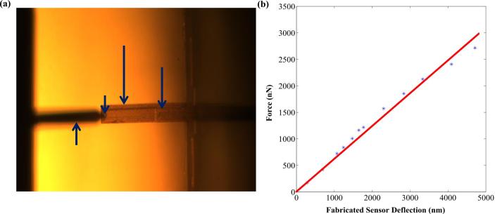
Where, d1 and d0 are the final and initial deflection of the AFM cantilever as sensed by the AFM photodiode and k is the spring constant. The schematic diagram and detailed calibration procedure is presented in our previous work (Pandya et al., 2014). For our present design of the cantilever (L= 260 μm, W= 35 μm and t= 2 μm) the calculated spring constant (k) was 0.6731 N/m (Pandya et al., 2014). The optical image of the reference cantilever (AFM cantilever) used for measuring the force curve on the test cantilever (piezoresistive microcantilever) is shown in Fig. 6(a). Figure 6(b) shows the force vs. deflection curve obtained by reference cantilever method. The measured spring constant of the fabricated microcantilever was found to be 0.6145 N/m.
FIGURE 6.
(a) Optical image of the AFM cantilever pressing the piezoresistive microcantilever for measuring the spring constant, and (b) force vs. deflection curve for measuring the spring constant.
3.2 Sensitivity Measurement and Sensor Performance on Breast Tissue
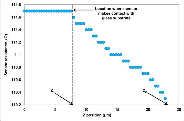
The resistance of the micro-cantilever was 111.7 Ω in its undeformed configuration. The fabricated microcantilever was pressed down on a hard glass substrate to measure its sensitivity. The change in PMC resistance was measured manually using Tektronix®TX3 multimeter. The change in resistance of the micro-cantilever is plotted as a function of the vertical distance (Z) in Fig. 7.
FIGURE 7.
Sensitivity measurement of the fabricated piezoresistive microcantilever.
At Z = Z1, the microcantilever touched the glass surface. The vertical displacement was increased till Z = Z2. The sensitivity, S, was calculated as:
| (1) |
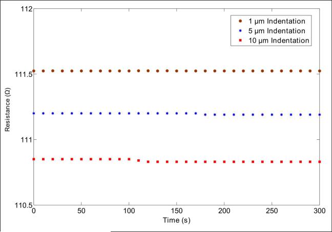
The sensitivity of the PMC was measured to be 10.85 μm/Ω. To measure time-dependent drift of the piezoresistive microcantilever, we indented the PMC for 1 μm, 5 μm and 10 μm on glass substrate. For each indentation, the PMC resistance was measured for 5 minutes. A change in PMC resistance vs. time for 1 μm, 5 μm, and 10 μm indentation is shown in Fig. 8. The resistance of PMC changes by 0.001 Ω (0.0008 % of maximum value 110.525 Ω), 0.01 Ω (0.0089 % of maximum value 111.2 Ω) and 0.02 Ω (0.0180 % of maximum value 110.85 Ω) for indentation of 1 μm, 5 μm, and 10 μm respectively.
FIGURE 8.
Time-dependent drift of piezoresistive microcantilever.
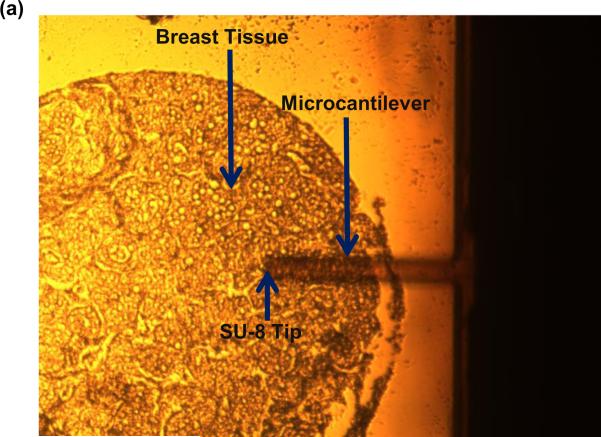
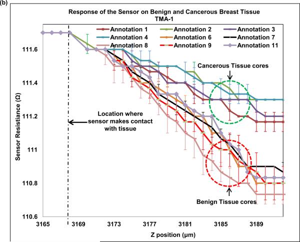
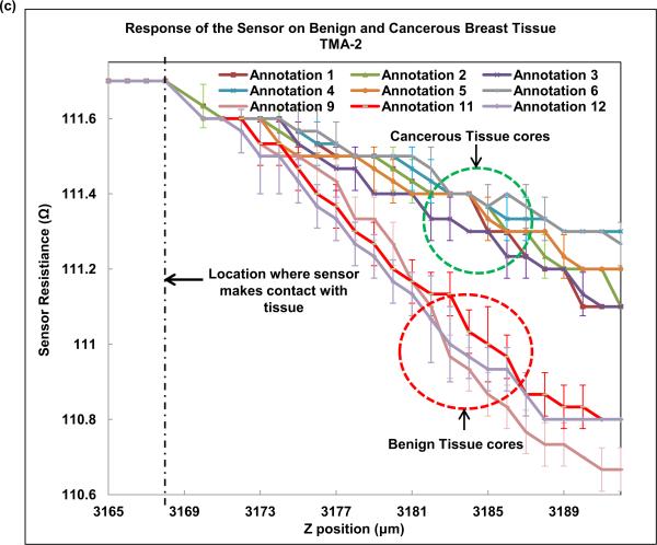
Next, we indented breast tissue cores with the fabricated piezoresistive microcantilever. Seven breast tissue specimens (4 cancer and 3 benign) were used in the present study. Normal breast is composed primarily of stroma. Normal breast glands are distributed as small and underdeveloped clusters in the organ. Despite our best effort, one benign specimen was excluded from the study as neither of the three TMA cores caught normal breast glands for analysis and thus three benign specimens were obtained. The optical photograph of microcantilever indenting the tissue is shown in Fig. 9(a). The piezoresistive microcantilever force sensor was indented at three different points in each of the 18 annotated ROIs. It was found that, for the same z-displacement, the change in resistance for benign breast epithelial was higher when compared to cancerous tissue cores. This indicates that tissues tend to become less stiff over the course of disease progression. Figure 9(b) and (c) shows the response of the sensor on TMA-1 and TMA-2 respectively.
FIGURE 9.
(a) Optical image of piezoresistive microcantilever indenting the breast tissue core, (b) sensor performance on TMA-1, and (c) sensor performance on TMA-2.
Multiple previous AFM studies have reported reduction in surface stiffness in breast cancer cell line or tissue compared to their benign counterparts (Roy et al., 2013; Plodinec et al., 2012). In this piezoresistive sensor experiment, we compressed the entire thickness of the tissue slice at designated regions and also found a consistent reduction in resistance in cancer ROIs. The tumor matrix and tumor cells should be distinguished when we assess tissue characteristics at microscopic level. That was the primary reason to probe into epithelial regions (tumor regions or normal glands) in our experiments. Due to small size of the sensor, the measured stiffness of tissue only reflected local characteristics, which corresponds to normal or cancerous breast epithelial cells. Our results are consistent with reported results, which shows decrease of stiffness in breast cancer cell lines versus their normal counterparts (Plodinec et al., 2012). The finding confirms that biomechanical changes in breast cancer development exist and is dependably measureable via micro- or nano- scale electromechanical sensors.
As demonstrated in this preliminary study, piezoresistive characteristics of tissue components displayed a convincing change according to their disease status. With a (good) potential to be miniaturized as an add-on to existing medical equipment, piezoresistive sensors can be envisioned to characterize tissue during surgical or even biopsy procedures. In such situations, the sensor can gather biomechanical data, which are independent of the existing visual and medical imaging data, and may help to better characterize tissue at biopsy site, or detecting tumor margin during surgery. We understand such implementation has a very long way to go before turning into reality. However, characterizing these mechanical changes in vivo can be a new direction in cancer detection and characterization. To provide robust diagnostic assistance with our method it is important to produce stable protocol and statistically sound measurement. In this article, we would like to share with the community our preliminary data and potential of the new approach. We carried out t-test for resistance values obtained by deflection of sensor for z-displacement of 8 μm. The p-value was found to be 0.00000000017, which indicates that the difference of change in resistance for z-displacement of 8 μm in case of benign and cancerous breast tissue is statistically significant. We intend to extend the experiment to more cases and more subclasses of breast tumors in subsequent studies. As our experiment scales up and the data starts to overlap amongst the tissue classes, producing a histogram of our specific measurement will be the go-to method to aggregate data.
The sample elastic modulus can be quantitatively obtained by curve fitting with appropriate analytical or computational contact models. In general, quantifying accurate mechanical properties of thin specimens such as the tissue cores studied in this work requires significant computational effort due to the absence of existing analytical contact models for thin specimen indentation using a flat cylindrical punch. As observed previously by Dimitriadis et al., substrate effects can cause significant overestimation in the elastic modulus (Dimitriadis et al., 2002). Recently, Wald et al. have proposed a finite element solution for studying the indentation response of thin films using a flat punch (Wald et al., 2013). The primary focus of this paper was to demonstrate the feasibility in using piezoresistive force sensors for differentiating the force response in normal and cancerous specimens, not as much to characterize the elastic modulus of the tissue specimens. Detailed contact modeling of the tissue response due to indentation loading using the piezoresistive cantilevers is currently out of this scope of this work, and we plan to investigate this in the future.
In the published literature on using AFM for obtaining nanomechanical signature of breast tissue (Plodinec et al., 2012) the results were presented in the form of small elastic maps (20 μm X 20 μm) at the locations of sampling. However, the authors were using a rough labeling of sampling area (a longitudinal location in the needle biopsy), and that the accompanying histologic images in the illustrations were not claimed to be from the exact region of AFM sampling and therefore did not provide any point-by-point correspondence to the elastic maps. In contrast, our sampling was guided by annotations on serial sections of the exact tissue be probed and hence provided better confidence in labeling of the sampled area being benign or tumor, epithelial, or stroma. Though AFM provides better resolution in the spatial domain, piezoresistive sensor may detect changes deeper from the surface in the process of continued indentation to render a diagnosis. While it is too early to predict how piezoresistive sensors compare to AFM in improving diagnosis, it could serve as a complimentary modality to AFM measurements.
It is known that scanning electron microscopy on biological specimen bears artifacts (Braet et al., 1997; Bray et al., 2005). Preparation of the SEM specimen followed the same protocol of preparing the tissue microarray specimen for piezoresistive sensing. The glass slide mounted with deparaffinized tissues was submerged in container with Phosphate-Buffered Saline (PBS) solution until SEM experiment. For FE-SEM, the slide from container was taken out and dipped in DI water and subsequently dried in Nitrogen (N2) environment. In the process of sample preparation for scanning electron microscopy, cells and tissue undergo different degrees of shrinkage whether the fixation was executed with freezing or chemical agents such as aldehyde. In our experiment, since the tissue was pre-cut while embedded in paraffin, what was imaged under FE-SEM probably reflected this shrinkage as well as contour of cellular structures, and we are aware that our images cannot be compared with those conventionally prepared for SEM. Nevertheless, the benign tissue ROIs were seen with smooth and supple texture under FESEM while the cancer regions showed different degrees of disruption and distortion. As cytoskeletal changes were reported in invasive carcinoma related to loss of epithelial polarity, cell adhesion, and migration, we hypothesize that our observations also originated from similar changes that allowed cancer cells to grow cytoplasmic extensions and invade adjacent tissue. The FFPE process described here denatures protein in biospecimens and renders them chemically inactive in many ways. However, the structure that mechanically supports the tissue (cytoskeleton and the extra-cellular matrix), still exists. The study described in this manuscript is an explorative endeavor in which we were encouraged to discover that the measurements on the deparaffinized FFPE tissue echoed biomechanical (AFM or otherwise) changes of cancer cell lines in in vitro models.
We further believe that the biomechanical characteristics are independent of the morphological characteristics of the tissue and they can potentially provide additional insight into tumorigenesis and progression. In addition, we envision using piezoresistive sensing at different temporal locations in cancer diagnosis.
4. Conclusions
This paper presents the fabrication and characterization details of piezoresistive microcantilevers aimed at electromechanical characterization of breast tissue specimens. The spring constant of the microcantilevers calibrated using the reference cantilever method showed good agreement with the theoretically computed spring constant, thus demonstrating the accuracy of the microfabrication process. We computed the sensitivity of the sensor by deflecting it against a hard glass substrate. The sensor was also found to be responsive to tissue indentation. The piezoresistive microcantilever was indented on benign and cancerous breast tissue cores obtained from 7 different specimens. Our preliminary results demonstrated that the force sensor can be used to demarcate cancerous and benign breast tissues and thus can be used to characterize histological tissue samples. We believe that this novel approach will potentially provide a unique pathway to gain further insight into the biomechanical changes from the onset through progression of breast cancer and other diseases. In our future work, an automated high-throughput electro-mechanical sensor for detection of cancerous breast tissues is envisaged.
Research Highlights.
- Accurate characterization of benign and cancerous breast tissues
- Assessing mechanical properties of breast tissue at the micro-scale
- Correlation to the tissue architecture
- Biomechanical data could help establish models of tumorigenesis and disease progression.
Acknowledgements
Research reported in this publication was supported by the National Cancer Institute of the National Institutes of Health under Award Number R01CA161375. The content is solely the responsibility of the authors and does not necessarily represent the official views of the National Institutes of Health. We acknowledge the support of Maryland Nanocenter for FE-SEM studies.
Footnotes
Publisher's Disclaimer: This is a PDF file of an unedited manuscript that has been accepted for publication. As a service to our customers we are providing this early version of the manuscript. The manuscript will undergo copyediting, typesetting, and review of the resulting proof before it is published in its final citable form. Please note that during the production process errors may be discovered which could affect the content, and all legal disclaimers that apply to the journal pertain.
References
- American Cancer Society Breast Cancer Facts & Figures 2013-2014. http://www.cancer.org/acs/groups/content/@research/documents/document/acspc-040951.pdf.
- Kim D, Wong PK, Park J, Levchenko A, Sun Y. Ann. Rev. Biomed. Eng. 2009;11:202–233. doi: 10.1146/annurev-bioeng-061008-124915. [DOI] [PubMed] [Google Scholar]
- Roy R, Chen W, Goodell L, Hu J, Foran D, Desai J. Proceedings of the International Conference on Biomededical Robotics and Biomech. Tokyo, Japan: 2010. pp. 710–715. [Google Scholar]
- Cross SE, Jin YS, Rao J, Gimzewski JK. Nat. Nanotechnol. 2007;2:780–783. doi: 10.1038/nnano.2007.388. [DOI] [PubMed] [Google Scholar]
- Plodinec M, Loparic M, Monnier CA, Obermann EC, Dallenbach RZ, Oertle P, Hyotyla JT, Aebi U, Bentires-Alj M, Lim RYH, Schoenenberger CA. Nat Nanotechnol. 2012;7:757–765. doi: 10.1038/nnano.2012.167. [DOI] [PubMed] [Google Scholar]
- Suresh S. Acta Mater. 2007;55:3989–4014. [Google Scholar]
- Swift J, Ivanovska IL, Buxboim A, Harada T, Dingal P, Pinter J, Pajerowski DJ, Spinler KR, Shin JW, Tewari M, Rehfeldt F, Speicher DW, Discher DE. Science. 2013;341:1240104–1 – 1240104-16. doi: 10.1126/science.1240104. [DOI] [PMC free article] [PubMed] [Google Scholar]
- Alessandrini A, Facci P. Meas. Sci. Technol. 2009;16:R65–R92. [Google Scholar]
- Seonghwan K, Rahman T, Senesac LR, Davison BH, Thundat T. Scanning. 2009;31:204–210. doi: 10.1002/sca.20159. [DOI] [PubMed] [Google Scholar]
- Sarajlic E, Boer M.J. de., Jansen HV, Arnal N, Puech M, Krijnen G, Elwenspoek M. J. Micromech. Microeng. 2004;14:70–76. [Google Scholar]
- Roy R, Chen W, Goodell L, Hu J, Foran D, Desai J. IEEE Trans. Autom. Sci. Eng. 2013;10:462–465. doi: 10.1109/TASE.2012.2226154. [DOI] [PMC free article] [PubMed] [Google Scholar]
- Gimzewski JK, Gerber C, Meyer E, Schlittler RR. Chem. Phys. Lett. 1994;217:589–594. [Google Scholar]
- Thundat T, Warmack RJ, Chen GY, Allison DP. Appl. Phys. Lett. 1994;64:2894–2896. [Google Scholar]
- Mukhopadhyay R, Sumbayev VV, Lorentzen M, Kjems J, Andreasen PA, Besenbacher F. Nano Lett. 2005;5:2385–2388. doi: 10.1021/nl051449z. [DOI] [PubMed] [Google Scholar]
- Ghatkesar MK, Lang HP, Gerber C, Hegner M, Braun T. PLoS One. 2008;3:1–6. doi: 10.1371/journal.pone.0003610. [DOI] [PMC free article] [PubMed] [Google Scholar]
- Backmann N, Zahnd C, Huber F, Bietsch A, Pluckthun A, Lang HP, Guntherodt HJ, Hegner M, Gerber CA. Proc. Natl. Acad. Sci. USA. 2005;102:14587–14592. doi: 10.1073/pnas.0504917102. [DOI] [PMC free article] [PubMed] [Google Scholar]
- Berger R, Delamarche E, Lang HP, Gerber C, Gimzewski JK, Meyer E, Guntherodt HJ. Science. 1997;276:2021–2024. [Google Scholar]
- Fritz J, Baller MK, Lang HP, Rothuizen H, Vettiger P, Meyer E, Guntherodt HJ, Gerber C, Gimzewski JK. Science. 2000;288:316–318. doi: 10.1126/science.288.5464.316. [DOI] [PubMed] [Google Scholar]
- Lang HP, Baller MK, Berger R, Gerber C, Gimzewski JK, Battiston FM, Fornaro P, Ramseyer JP, Meyer E, Guntherodt HJ. Anal. Chim. Acta. 1999;393:59–65. [Google Scholar]
- Merlos A, Santander J, Alvarez M, Campabadal F. J. Micromech. Microeng. 2000;10:204–208. [Google Scholar]
- Bae B, Flachsbart BR, Park K, Shannon MA. J. Micromech. Microeng. 2004;14:1597–1607. [Google Scholar]
- Pramanik C, Saha H, Gangopadhyaym U. J Micromech. Microeng. 2006;16:2060–2066. [Google Scholar]
- Boisen A, Thundat T. Mater. Today. 2009;12:32–38. [Google Scholar]
- Gautsch S, Akiyama T, Imer R, Rooij N.F. de., Staufer U, Niedermann P, Howald L, Brandlin D, Tonin A, Hidber HR, Pike WT. Surf. Interface Anal. 2002;33:163–167. [Google Scholar]
- Hierlemann A, Lange D, Hagleitner C, Kerness N, Koll A, Brand O, Baltes H. Sensor Actuat. 2000;B70:2–11. [Google Scholar]
- Kanda Y, Yasukawa A. Sensor Actuat. 1997;A62:539–542. [Google Scholar]
- Cho CH, Jaeger RC, Suhling JC, Kang Y, Mian A. IEEE Sensors J. 2008;8:392–400. [Google Scholar]
- Yang M, Zhang X, Vafai K, Ozkan CS. J. Micromech. Microeng. 2003;13:864–872. [Google Scholar]
- Loui A, Goericke F, Ratto T, Lee J, Hart B, King W. Sensor Actuat. 2008;A147:516–521. [Google Scholar]
- Harley JA, Kenny TW. Appl. Phys. Lett. 1999;75:289–291. [Google Scholar]
- Pandya HJ, Kim HT, Roy R, Desai JP. Mater. Sci. Semicond. Process. 2014;19:163–173. doi: 10.1016/j.mssp.2013.12.016. [DOI] [PMC free article] [PubMed] [Google Scholar]
- Choudhury A, Hesketh PJ, Thundat T, Hu Z. J. Micromech. Microeng. 2007;17:2065–2076. [Google Scholar]
- Gates RS, Reitsma MG, Kramar JA, Pratt JR. J. Res Natl Inst Stan. 2011;116:703–727. doi: 10.6028/jres.116.015. [DOI] [PMC free article] [PubMed] [Google Scholar]
- Hutter JL, Bechhoeffer J. Review Sci. Instrum. 1993;64(7):1868–1873. [Google Scholar]
- Dimitriadis EK, Horkay F, Maresca J, Kachar B, Chadwick RS. Biophys J. 2002;82(5):2798–2810. doi: 10.1016/S0006-3495(02)75620-8. [DOI] [PMC free article] [PubMed] [Google Scholar]
- Wald MJ, Considine JM, Turner KT. Exp Mech. 2013;53:931–941. [Google Scholar]
- Braet F, Zanger RD, Wisse E. J. Microsc. 1997;186:84–87. doi: 10.1046/j.1365-2818.1997.1940755.x. [DOI] [PubMed] [Google Scholar]
- Bray DF, Bagu J, Koegler P. Microsc Res Tech. 2005;26:489–495. doi: 10.1002/jemt.1070260603. [DOI] [PubMed] [Google Scholar]


