Abstract
This paper describes the design and performance of a high spatial resolution PET detector with time-of-flight capabilities. With an emphasis on high spatial resolution and sensitivity, we initially evaluated the performance of several 1.5 × 1.5 and 2.0 × 2.0 mm2 and 12–15 mm long LYSO crystals read out by several appropriately sized PMTs. Experiments to evaluate the impact of reflector on detector performance were performed and the final detector consisted of a 32 × 32 array of 1.5 × 1.5 × 15 mm3 LYSO crystals packed with a diffuse reflector and read out by a single Hamamatsu 64 channel multi-anode PMT. Such a design made it compact, modular and offered a cost-effective solution to obtaining excellent energy and timing resolution. To minimize the number of readout signals, a compact front-end readout electronics that summed anode signals along each of the orthogonal directions was also developed. Experimental evaluation of detector performance demonstrates clear discrimination of the crystals within the detector. An average energy resolution (FWHM) of 12.7 ± 2.6% and average coincidence timing resolution (FWHM) of 348 ps was measured, demonstrating suitability for use in the development of a high spatial resolution time-of-flight scanner for dedicated breast PET imaging.
I. Introduction
While the importance of detector spatial resolution and sensitivity on overall PET performance are well understood, including the time-of-flight (TOF) information has been shown to improve the quantitative powers of PET [1–4]. With the resurfacing of TOF PET in this past decade there have been significant advances in developing high performance detectors [5–6]. In particular, there has been a push to improve the timing resolution of detectors for TOF PET. The improvements in timing resolution have usually resulted in limiting the system spatial resolution or sensitivity, and researchers are still exploring ways to develop a detector with high spatial and timing resolutions. We describe here the development of a high spatial resolution scintillation detector with TOF capabilities. While such a detector would have numerous applications, we are particularly interested in demonstrating its relevance in a partial ring dedicated breast PET scanner where the TOF data is expected to help mitigate artifacts arising from the limited angular sampling of the breast [7–8].
Previously [9], we had reported on the design and performance of an initial design of one such high spatial resolution TOF detector. The detector design was based on the pixelated Anger-logic detector [10] where an array of individual crystals is read out by an array of larger PMTs coupled to it via a lightguide. A 7-PMT array of 13 mm diameter PMTs was used to read out an array of 1.5 × 1.5 × 12 mm3 LYSO crystals. While the detector produced sufficiently good flood images with good crystal discrimination and a coincidence timing resolution of ~490 ps, the measured timing resolution was poorer in comparison with results obtained with single crystals directly coupled to a single PMT. The loss in timing resolution is mainly due to the insensitive photocathode area surrounding the PMTs used in that detector.
The present paper describes the design and performance of an improved, modular detector whose TOF performance is closer to measurements with individual crystals directly coupled to the PMT. We first assess the timing performance of several individual small cross-section crystals read out using several fast PMTs to demonstrate the feasibility of achieving very good timing with such small, long crystals. Experiments to evaluate the impact of two commonly used reflector materials for building a larger crystal array are also performed. Dedicated front-end readout electronics that summed the anode signals from a multi-anode PMT along the orthogonal directions to reduce the number of readout channels from the detector are designed and fabricated. Finally, a complete detector module is assembled and its performance evaluation is presented.
II. Materials and Methods
All measurements in this paper have been performed using NIM electronics, CAMAC based data acquisition system. Measurements to evaluate detector performance were performed with a reference detector comprised of a small Saint Gobain Brilliance detector (~1 cm3 LaBr3) coupled to a Photonis XP20D0 PMT. Two such reference detectors were measured to have a coincidence timing of 225 ps FWHM. The PMT under test (Table I) was biased at the manufacturer recommended bias voltage. Data collection was performed with a 511 keV 22Na source placed between the test and reference detectors. All measurement results reported in this paper are calculated and reported as the coincidence timing resolution from two test detectors, after correcting for the contribution from the reference detector.
Table I.
A comparison of select commercially available fast photomultiplier tubes appropriate for the development of a high spatial resolution TOF PET detector. All the above tubes are manufactured by Hamamatsu Photonics [15]. Except for the H8500, which is a square multi-anode tube, all other PMTs listed above are circular. The H8500 has an 8 × 8 array of anodes with a pitch of 6.08 mm.
| PMT Model (diameter, mm) | Gain (106) | Quantum Efficiency (at 420 nm) | Transit time spread (ns) | Rise time (ns) |
|---|---|---|---|---|
| R4998 (25) | 5.7 | 18 | 0.16 | 0.70 |
| R3478 (19) | 1.7 | 27 | 0.36 | 1.30 |
| R4124 (13) | 1 | 25 | 0.50 | 1.10 |
| R1635 (10) | 1 | 25 | 0.50 | 0.80 |
| H8500 (52)* | 1.5 | 25 | 0.40 | 0.80 |
square, multi-anode PMT
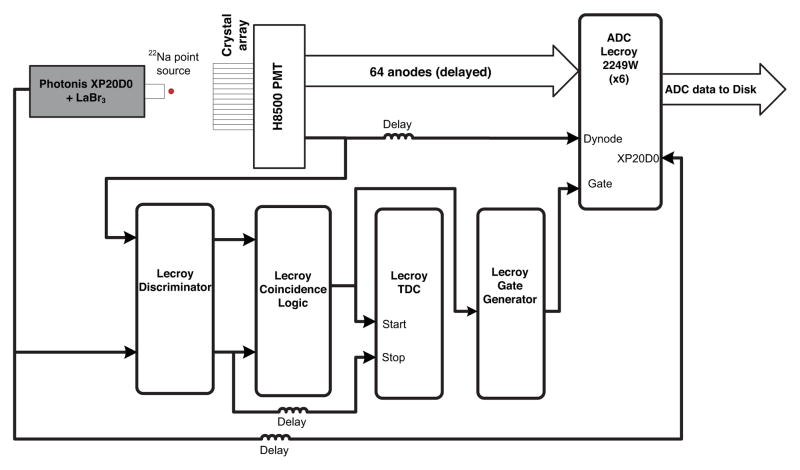
For tests with the single channel PMTs, signals from both the reference PMT and the PMT under test were fed to a rise time compensated fast timing discriminator (LRS 825Z). The resulting trigger signals were then passed on to a coincidence logic unit to generate a coincidence signal that was used as the DAQ trigger as well as the start signal for a TDC with 25 ps resolution. The energy information was measured from an identical copy of the signal used as described above to generate the timing information. For the multi-anode PMT, the dynode signal was used to extract both the energy and timing information, and the energy in multiple anodes was used to calculate the 511 keV photon interaction position in software using Anger logic. Each of the 64 anodes from the multi-anode PMT was read out by a separate Lecroy charge integrating ADC. Fig. 1 shows the schematic of the experimental setup used for the measurements. The DAQ was controlled by a LabVIEW program, which saved the PMT and TDC information in listmode format. All the data analysis was performed offline using software developed in MATLAB.
Fig. 1.
A schematic of the experimental setup and data acquisition system used to perform detector measurements.
A. Timing resolution with small cross-section scintillation crystals
It is well known that the timing resolution of a scintillation detector is directly related to the light yield and light collection efficiency in the scintillator [11]. Since small cross-section and long crystals have inherently poorer light collection efficiency [12–13], it was important to assess the feasibility to obtain good timing performance. Hence we evaluated the timing performance of several small and long crystals directly coupled to fast PMTs appropriate for a TOF detector design. Table I lists the PMTs and their specifications that were used in this study. The R4998 is one of the best-in-class TOF PMTs and was used to benchmark the timing performance that could be achieved with the small cross-section crystals. The R3478 is identical in size to the 19 mm PMTs used to read out an array of 2 × 2 × 10 mm3 crystals as used in the development of a small animal PET scanner [14]. The R4124 and R1635 are fast PMTs that are smaller in size and may be appropriate for use in detectors where crystals smaller than 2 × 2 mm2 in cross-section need to be discriminated. The H8500 is a multi-anode PMT that has good timing characteristics and is cost-effective in comparison with the R4124 and R1635 single channel PMTs for decoding larger crystal arrays. In addition, the H8500 allows a modular detector design that provides flexibility in the design of a scanner.
With a target spatial resolution of 1–2 mm, we evaluated the timing resolution achieved with Lu1.8Y.2SiO5:Ce (lutetium oxyorthosilicate, LYSO) crystals of small cross-sections (1.5 × 1.5 mm2 & 2.0 × 2.0 mm2). To achieve good detector sensitivity, crystal lengths of 12–15 mm were chosen. Each of the crystals was wrapped in several layers of Teflon on five sides and grease coupled (BC-630, Saint-Gobain Crystals) directly to each of the different PMTs listed in Table I. For comparison, we also performed measurements with a 4 × 4 × 22 mm3 LYSO crystal that is similar in size to the crystals used in some commercial whole-body TOF PET scanners.
B. Detector design and impact of reflector material
In previous work we have shown that the active area of the PMT is an important criterion in designing a large area high spatial resolution detector with good performance i.e. crystal discrimination, energy and timing resolution [9]. The use of a multi-anode PMT such as the H8500 should improve the active area, minimize the deterioration in detector performance arising from light loss and also provide a relatively cost-effective, modular design. The smaller sized anodes should increase the detector sampling, improving crystal discrimination. With a 6.08 mm anode pitch, the entrance glass window on the H8500 PMT (1.5 mm) provides enough light sharing to help decode crystals that are smaller than the anode pitch. In addition, as will be later shown in Section III.A, the H8500 provides good timing resolution as well, making it appropriate for use in the design of a TOF detector. We therefore chose to investigate use of the H8500 PMT for developing a multi-crystal detector with good timing performance and crystal discrimination. Fig. 2 shows the schematic of the detector. A few groups have previously designed PET detectors utilizing the H8500 PMT to read out scintillation crystals with cross-section of about 2 × 2 mm2 [16–18]. While these investigations have reported good crystal discrimination they have not carefully studied the timing performance or considered their use for TOF PET.
Fig. 2.

A schematic of the detector design, left: side view, right: top view. The detector consists of an array of scintillators read out by a single multi-anode PMT. With minimal dead space, the design is compact, modular and offers a good compromise between cost and achieving very good detector performance.
Initial experiments (Section II.A) to assess the expected timing performance with individual, small crystals were performed by wrapping the crystal with several layers of Teflon. While Teflon is a well regarded reflector, this technique does not extend well to building large, close packed arrays with small scintillation crystals. Hence we studied the impact of two different reflector crystal assembly techniques used in the manufacture of larger crystal arrays. A 13 × 11 array of polished 1.5 × 1.5 × 12 mm3 LYSO crystals was assembled with a 100 μm thick white plastic reflector incorporated in a transparent adhesive typically used to bond crystals into a monolithic block. The above technique is known to be robust, allows ease of array assembly, and is hence commonly used to manufacture scintillation arrays with high packing density [19–20]. Since reflector performance was expected to impact detector performance with high aspect ratio crystals, in parallel, an 8 × 7 array of same size crystals was also assembled using a 75 μm thick layer of diffuse sheet reflector without any adhesive bonding. Fig. 3 shows a photo of the two assembled prototype crystal arrays. Measurements to evaluate crystal discrimination in a flood map, as well as to obtain the energy and timing resolution of individual crystals by gating on events within each crystal, were performed for both crystal arrays.
Fig. 3.
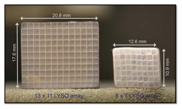
Left: Photo of a single 13 × 11 array of 1.5 × 1.5 × 12 mm3 LYSO crystals assembled using a white plastic reflector incorporated in a transparent adhesive used to bond the crystals in an array. Right: Photo of a single 8 × 7 array of similar sized LYSO crystals assembled using a diffuse sheet reflector without any adhesive bonding.
C. Reducing the number of readout channels from the multi-anode PMT
Our previous simulation studies and experiments [9] had suggested 13 mm diameter PMTs to be sufficient for obtaining good crystal discrimination. Hence, while the 6.08 mm sized anodes provided better sampling, we were interested in determining if we could reduce the number of readout channels from the PMT without significantly degrading the detector energy and timing resolution performance. The reduced number of readout channels would make the detector design cost-effective and practical when building a scanner. To evaluate its feasibility, we used the previously acquired detector data with the 8 × 7 crystal array coupled to the H8500 PMT (Section II.B). From the listmode data, the 64 anode signals were reduced in software to 8+8 row-column anode sums i.e. 8 each along both the orthogonal directions. The reduction did not correct for the gain variation among the anodes. Once again, measurements to evaluate crystal discrimination in a flood map, as well as to obtain the energy and timing resolution of individual crystals, were performed using both, the 64 anodes and 8+8 row-column anode sums datasets.
D. Hardware design of row-column sum readout electronics
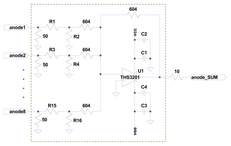
In conjunction with the feasibility studies described in Section II.C, we also built dedicated front-end electronics to implement the 8+8 row-column anode sums in hardware. Other groups have previously built readout electronics for multi-channel PMTs [21–22], and have typically made use of a resistive network and charge division to reduce the number of PMT outputs and provide a position sensitive detector. Others [23–24] have included a more sophisticated approach to incorporate a method of correcting for the anode gain nonuniformities. While these techniques have been shown to work well, we observed that the anode gain non-uniformities (maxanode gain/meananode gain = 1.25, minanode gain/meananode gain = 0.81, σanode gain/meananode gain = 0.09; as provided by the manufacturer’s specification sheet [15]) did not have a significant effect on the performance of our detector. Hence we adopted a simpler technique to realize the electronic circuit as shown in Fig. 4.
Fig. 4.
Schematic of the circuit used to realize the anode summing circuit in the front-end electronics for read out of the multi-anode PMT. While a single summing circuit is shown here (in the dotted region), the entire PMT readout consists of 16 such summing circuits with each anode contributing to two separate anode summing circuits.
The current output from each anode is first converted into a voltage and then sent to two anode summing circuits, one each for a row sum and a column sum (dotted region in Fig. 4 shows a single summing circuit). Each summing circuit uses a wideband, high speed current feedback amplifier (Texas Instruments THS3201). A resistive network (R1–R16) is also included to adjust for the anode gain non-uniformities, though we did not utilize this part in current work. The entire readout board consists of 16 such summing circuits. Each of the row/column sum signals is buffered using an additional op-amp (not shown in Fig. 4) and routed to a micro miniature coaxial connector on the I/O board. The dynode signal is buffered with a variable gain amplifier using the same fast op-amp as mentioned above. Separate copies of the dynode signal are made available for energy and timing measurement. The variable gain amplifier provides the flexibility to adjust the dynode gain when using several detectors in a scanner. The entire readout was designed to be mechanically compact and allow packing of multiple readout modules in the dedicated breast scanner that is being developed. In this work the 8+8 row-column anode sums are integrated with the LeCroy charge integrating ADCs (see Fig. 1), followed by position calculation using Anger-logic in software.
III. Results
A. Timing resolution with small cross-section scintillation crystals
Our timing measurements (Table II) indicate that directly coupling the small cross-sectional crystals with suitable fast PMTs yields comparable (or better) timing resolution to that presently achieved with crystals used in clinical whole-body TOF PET scanners [25–27]. While some systematic effects can be observed, these results nevertheless demonstrate their suitability for building a high spatial resolution TOF PET detector. While care was taken to collect data with enough statistics and test for repeatability, an average of the measurements across both, different crystals sizes (Table II, last row) and across the different individual PMTs (Table II, rightmost column) better represents some of the trends we observe.
Table II.
Coincidence timing measurements for different (size) individual LYSO crystals placed directly on several test PMTs outlined in Table I. The timing measurements indicate that comparable or better timing can be achieved even with small and long scintillation crystals. Measurements with a 4 × 4 × 22 mm3 LYSO crystal are also shown for comparison.
| Hamamatsu PMT model (size, mm) | Coincidence timing resolution (ps, FWHM) | ||||
|---|---|---|---|---|---|
| 4 × 4 × 22 mm3 LYSO (polished surfaces) | 2 × 2 × 15 mm3 LYSO (polished surfaces) | 1.5 × 1.5 × 12 mm3 LYSO (polished surfaces) | 1.5 × 1.5 × 12 mm3 LYSO (diffused entrance, other faces polished) | Average timing resolution for each PMT | |
| R4998 (25) | 274 | 283 | 341 | 334 | 308 |
| R3478 (19) | 376 | 367 | 367 | 343 | 363 |
| R4124 (13) | 392 | 367 | 343 | 334 | 359 |
| R1635 (10) | 247 | 283 | 265 | 247 | 260 |
| H8500 (52)* | 309 | 329 | 292 | 312 | 310 |
| Average timing resolution for each crystal | 320 | 326 | 322 | 314 | |
square, multi-anode PMT
The faster rise time of the R1635 PMT results in better timing resolution in comparison with the R4124. The marginally better rise time, but slightly worse transit time spread of the R4124 in comparison with the R3478 results in comparable timing resolution for these two PMTs. The R4998 PMT has the best rise time and transit time spread, but the R1635 offers the best overall timing resolution due to its higher quantum efficiency. Overall, the H8500 provides good timing resolution that is similar to our benchmark R4998 PMT. For our detector we chose the H8500 over the R1635 (which gives the best timing resolution) due to its potential for achieving good crystal discrimination of the 1.5 × 1.5 mm2 cross-section crystals in a cost-effective manner.
B. Detector design and impact of reflector material
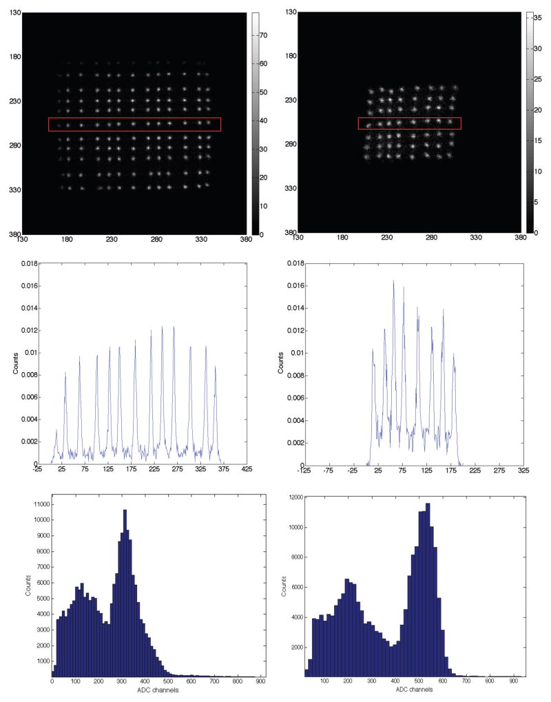
Flood images acquired with the two crystal arrays assembled with the two different reflector materials placed at the center of the H8500 PMT are shown in Fig. 5. While all the crystals can be clearly separated in both the arrays, the flood quality is better with the adhesive bonded, white plastic reflector array having improved peak-to-valley ratio. However, the average energy and coincidence timing resolution for all crystals within the diffuse sheet reflector array is improved in comparison to the adhesive bonded white plastic reflector array (Table III).
Fig. 5.
Top row: Flood images acquired with the 13 × 11, adhesive bonded, white plastic reflector array and the 8 × 7 diffuse sheet reflector array placed on the H8500 PMT. Middle row: Profiles drawn through a single row of crystals (indicated in red) from the flood images acquired above. Bottom row: Representative energy spectra from the above described arrays. The array assembled with the adhesive bonded, white plastic reflector shows a DOI dependent variation in light collection that results in a decrease in overall collected light. Left and Right columns show results for the 13 × 11, adhesive bonded, white plastic reflector array and the 8 × 7 diffuse sheet reflector array, respectively.
Table III.
Average energy and timing performance measured for all individual crystals from the 8 × 7 and 13 × 11 LYSO array described above. All measurements were performed with a 511 keV source and sufficient statistics. While we present average energy and timing resolution, measurement for each individual crystal had 5% precision.
| H8500 multi-anode PMT | Prototype 13×11 array of 1.5×1.5×12 mm3 LYSO crystals assembled with a adhesive bonded, white plastic reflector | Prototype 8×7 array of 1.5×1.5×12 mm3 LYSO crystals assembled with a diffuse sheet reflector |
|---|---|---|
| Energy resolution (% FWHM) | 18.7 ± 1.8 | 13.8 ± 1.8 |
| Timing resolution (FWHM) | 562 ± 15 ps | 319 ± 11 ps |
With the plastic reflector there is a depth-of-interaction (DOI) dependent variation in the light collection efficiency and overall decrease in the collected light that explains the degradation in the energy and timing resolutions (see Fig. 5 Bottom). It is also important to note that the average coincidence timing resolution with the diffuse sheet reflector is very close to measurements when using a single 1.5 × 1.5 × 12 mm2 crystal (albeit shorter, 12 mm as opposed to 15 mm long in the final detector design) directly coupled to the H8500 PMT (Table II).
C. Effect of reducing the number of readout channels from the multi-anode PMT
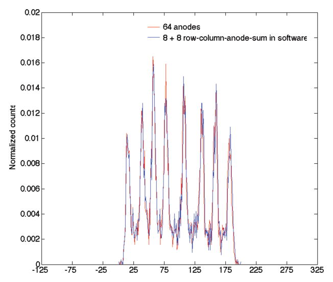
Fig. 6 shows the flood image generated from the 64 anodes and the reduced 8+8 row-column anode sums performed in software. As demonstrated there is only a marginal deterioration in the flood image with all crystals well discriminated. While the dynode signal is used to measure the energy and timing information, any event mispositioning arising from the row-column sum procedure can also affect the measured energy and timing resolution for each crystal in the array. Hence to assess its impact, we also assessed the energy and timing resolution for all individual crystals within the 8 × 7 array by gating on events within each crystal region in the floodmap. Table IV reports the average energy and timing resolution for all 56 crystals from the crystal array that was used for this measurement. As shown, the row-column sum reduction has almost no impact on the reported energy and timing resolution. The measurements shown in Fig. 6 were performed with the array placed at the center of the PMT, and a similar trend was also observed when the crystal array was shifted towards the corner of the PMT (data not shown).
Fig. 6.
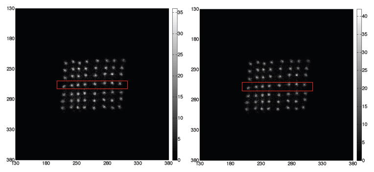
Top row, left column: Flood image from the 8 × 7 diffuse sheet reflector array measured using information from all 64 anodes of the H8500 PMT. Top row, right column: Flood image from the same array derived by performing a software based reduction of the 64 anodes to 8+8 anodes. Bottom row: Profile drawn through a single row of crystals (indicated in red).
Table IV.
Average energy and timing resolution for the 56 crystals under the two scenarios discussed above. All measurements were performed with a 511 keV source and sufficient statistics. While we present average energy and timing resolution, measurement for each individual crystal had 5% precision.
| 8×7 array of diffuse sheet-reflector wrapped 1.5 × 1.5 × 12 mm3 LYSO crystals readout by the H8500 multi-anode PMT | Using information from all the 64 (8 × 8) anodes | By performing a software reduction of the 64 anodes to a 8+8 sum along the two orthogonal directions |
|---|---|---|
| Energy resolution (% FWHM) | 13.8 ± 1.8 | 14.1 ± 1.9 |
| Timing resolution (FWHM) | 319 ± 11 ps | 321 ± 10 ps |
D. Final design and experimental performance of finalized detector module
Since the detector is being designed for use in a dedicated breast scanner, the final design comprised of a 32 × 32 array of polished 1.5 × 1.5 × 15 mm3 LYSO crystals assembled with a 50 μm layer of the diffuse sheet reflector. The number of crystals and reflector thickness were chosen to maximize the packing fraction of the detector without significantly degrading overall detector performance. The scintillation crystals are coupled to the Hamamatsu H8500 multi-anode PMT with its high voltage divider circuit modified to ensure sufficient divider current for operation at ~200 kcps, rates that we expect to encounter in our dedicated breast scanner (Hamamatsu H11951, [28]). The scintillator-PMT assembly is enclosed in a very thin carbon fiber housing that provides minimal gamma-ray attenuation (Fig. 7, left). The detector design is compact and modular, providing the ability to close pack them when building a complete scanner [8].
Fig. 7.
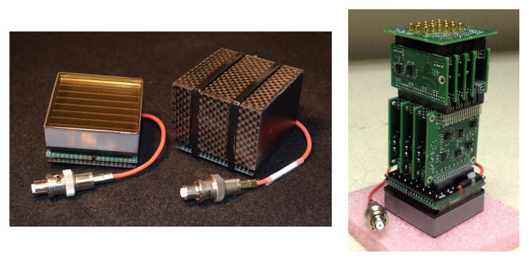
Left: Photo of a single Hamamatsu H11951 multi-anode PMT and a fully assembled, packaged detector module. The detector module consists of a 32 × 32 array of 1.5 × 1.5 × 15 mm3 LYSO crystals coupled directly to the multi-anode PMT. The scintillator PMT assembly is enclosed within a very thin carbon fiber housing that provides minimal gamma ray attenuation. Right: Photo of the compact front-end readout electronics attached to the multi-anode PMT. The electronics reduces the 64 anodes to 8+8 row-column anode sums, 8 each along both the in-plane directions.
Performance evaluation of a fully assembled detector module housing a 32 × 32 array of crystals was performed in conjunction with a hardware design of the row-column anode sum front-end readout electronics described earlier (Section II.D) and shown in Fig. 7, right. The experimental setup was very similar to the one outlined in Fig. 1. Instead of using all 64 anodes from the PMT, the 8+8 row-column anode sums generated by the dedicated readout electronics were each read out with a charge integrating ADC. As explained earlier, energy and timing information was generated from the dynode signal, while position was computed in software using Anger-logic with the 8+8 row-column anode sums. The readout electronics did not correct for the individual anode gain nonuniformities, but during data analysis the row-column anode sum signals were normalized using the PMT anode gain information provided by the manufacturer.
Fig. 8 (left) shows the flood map generated from the measurement with the finalized detector module using events with deposited energy > 440 keV (photopeak events). As can be seen, most of the 1024 crystals can be clearly resolved, demonstrating the potential for achieving good spatial resolution with this detector. The somewhat degraded discrimination of the edge crystals (last row and columns) can be explained by the poorer light collection on account of them extending slightly beyond the PMT active photocathode footprint (49 × 49 mm2). Also shown in Fig. 8 (right) is a profile drawn through a single row of crystals (highlighted in red). The flood quality from the final detector module is very similar to results obtained from the prototype array assembled with a diffuse sheet reflector (Fig. 5, middle row, right). We also report the energy and timing resolution for the detector. An automated algorithm was used to segment the 32 × 32 crystal array flood map using Voronoi decomposition [29] into a lookup table that maps each measured interaction position in the flood map to a physical crystal in the detector array. As shown in Fig. 8, the grid of yellow lines shows the result of this segmentation algorithm.
Fig. 8.
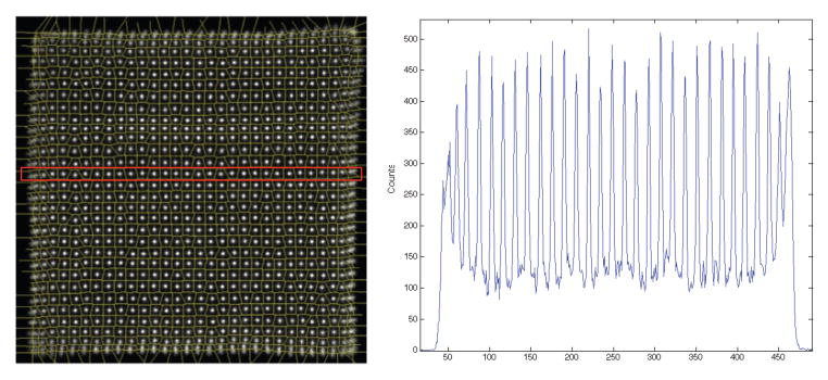
Left: Flood histogram acquired from the final detector assembled as shown in Fig. 7. The detector was read out by the compact readout electronics also shown in Fig. 7. Right: A profile (indicated in red) drawn through a single row of acquired flood histogram. As can be seen, 30 – 31 crystals can be clearly resolved in the flood map. The poorer discrimination over the edge crystal is on account of the crystal extending beyond the active area of the PMT.
The crystal look-up table was then used to assign each event to a given crystal. In this manner, energy (all events) and timing (events depositing > 440 keV in energy) spectra were generated for each crystal. A Gaussian fit was performed to the energy and timing spectra peaks to estimate the respective FWHM values. Fig. 9 shows representative energy and timing spectra for interactions from a single crystal within the detector. The measured energy and timing resolution is very uniform over most of the detector, except the edge crystals (Figs. 10 and 11). As explained above, this arises from the poorer light collection which somewhat degrades both the energy and timing resolution. An average energy resolution of 12.7 ± 2.6 % FWHM (Fig. 10) and an average coincidence timing resolution of 348 ± 39 ps FWHM (Fig. 11) was measured for all 1024 crystals within the detector module.
Fig. 9.
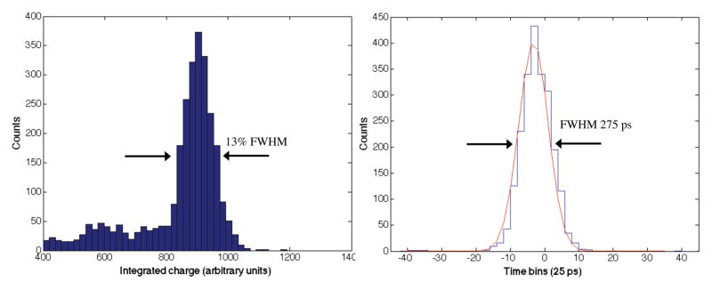
Representative energy (left) and coincidence timing (right) spectra for interactions within a single 1.5 × 1.5 × 15 mm3 LYSO crystal from the finalized detector module.
Fig. 10.
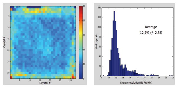
2D map (left) and histogram (right) of the measured energy resolution for all 1024 crystals from the finalized detector module. An average energy resolution of 12.7 ± 2.6 % FWHM was measured.
Fig. 11.
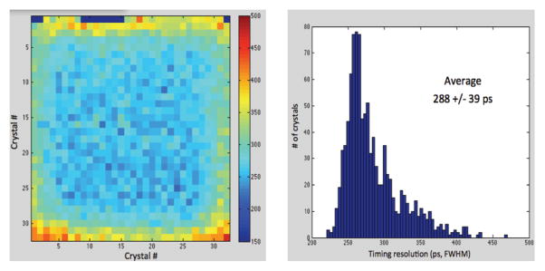
2D map (left) and histogram (right) of the measured coincidence timing resolution for all 1024 crystals from the finalized detector module. An average timing resolution of 288 ± 39 ps was measured. After accounting for the contributions from the reference detector (225 ps for two reference detectors in coincidence), an average coincidence timing resolution (FWHM) of 348 ps is calculated for two such detectors in coincidence.
IV. Discussion & Conclusion
This paper describes the design and performance of a high spatial and timing resolution PET detector. With a target spatial resolution of 1–2 mm we initially studied the timing performance of several single, small cross-sectional crystals read out by fast PMTs. While our measurements show some systematic effects based on the PMT specifications, our results demonstrate that very good timing resolution can be obtained with small and long scintillation crystals. In particular, our results demonstrate that the crystal cross-section can be reduced from 2 × 2 mm2 to 1.5 × 1.5 mm2, and crystal length increased from 12 mm to 15 mm (35% increase in coincidence photopeak efficiency), without sacrificing timing resolution. Overall, timing performance of the H8500 PMT is comparable to the R4998 PMT, which is one the best-in-class TOF PMTs. Additionally, the H8500 multi-anode PMT is compact in size, and offers a modular design at moderate cost for building a scanner. Hence it was our PMT of choice for further evaluation of a multi-crystal PET detector. Experiments with small detector arrays to assess the impact of reflector choice for building larger close packed arrays were performed and it was observed that the diffuse reflector crystal assembly without adhesive bonding was better suited for such a design due to excellent energy and timing resolution while also maintaining good crystal separation. Use of a white plastic reflector incorporated in a transparent adhesive used for bonding the crystals resulted in poorer light collection and also a DOI dependent variation in light collection efficiency. Based on these set of results our choice for the final detector design was a 32 × 32 array of 1.5 × 1.5 × 15 mm3 LYSO crystals assembled with a 50 μm thick layer of the diffuse sheet reflector. The choice of crystal length was a compromise between obtaining good system coincidence sensitivity and limiting the degradation in imaging performance arising due to parallax error [30]. To minimize the number of readout channels, compact front-end electronics that summed anode signals along each of the orthogonal directions was also developed. Experimental performance evaluation of a complete detector module demonstrates excellent energy, timing resolution and clear discrimination of most crystals. The reduced discrimination of edge crystals suggests that while almost 90% of the detector will have an intrinsic spatial resolution of 1.5 mm, near the detector edges this resolution will be close to 3 mm. Characterizing the impact on the reconstructed system spatial resolution is, however, beyond the scope of our current work. An average energy resolution (FWHM) of 12.7 ± 2.6 % and average coincidence timing resolution (FWHM) of 348 ± 39 ps for two such detector modules was measured for all 1024 crystals in the detector. In comparison, current state-of-the-art whole-body clinical TOF PET scanners use crystals with 4 × 4 mm2 cross-section and achieve a coincidence timing resolution of 500 – 600 ps [25–27]. The energy and timing measurements of the final detector module are consistent with our initial characterization using single crystals directly coupled to a single PMT, and also the prototype 8 × 7 array that was assembled with a diffuse sheet reflector. It also satisfies our design goals of building a high spatial resolution TOF detector suitable for use in a dedicated breast PET scanner. Design optimization studies of partial ring TOF breast PET scanner has suggested that a high spatial resolution detector with 300 – 600 ps timing resolution could aid in providing tomographic images with relatively fewer artifacts and good lesion uptake estimation relative to other non-TOF partial ring scanner designs [7].
Acknowledgments
This work was supported in part by the National Institutes of Health under grants R01EB009056 (National Institute of Biomedical Imaging and Bioengineering), R01CA113941 (National Cancer Institute) and a research agreement with Saint-Gobain crystals.
The authors wish to thank Mike Mayhugh and Louis Perna at Saint-Gobain Crystals for their collaboration and help in assembling the scintillation crystals and detector.
Contributor Information
Srilalan Krishnamoorthy, Department of Radiology, University of Pennsylvania, Philadelphia, PA 19104 USA.
Benjamin LeGeyt, Department of Radiology, University of Pennsylvania, Philadelphia, PA 19104 USA.
Matthew E. Werner, Department of Radiology, University of Pennsylvania, Philadelphia, PA 19104 USA
Madhuri Kaul, Department of Radiology, University of Pennsylvania, Philadelphia, PA 19104 USA.
F. M. Newcomer, Department of Physics and Astronomy
Joel S. Karp, Departments of Radiology and Physics & Astronomy at the University of Pennsylvania.
Suleman Surti, Email: srilalan@mail.med.upenn.edu, Department of Radiology, University of Pennsylvania, Philadelphia, PA 19104 USA.
References
- 1.Budinger TF. Time-of-Flight positron emission tomography: status relative to conventional PET. J Nucl Med. 1983;24:73–76. [PubMed] [Google Scholar]
- 2.Surti S, Karp JS, Popescu LM, Daube-Witherspoon ME, Werner M. Investigation of time-of-flight benefit for fully 3-D PET. IEEE Trans Nucl Sci. 2006;25(5):529–538. doi: 10.1109/TMI.2006.871419. [DOI] [PubMed] [Google Scholar]
- 3.Karp JS, Surti S, Daube-Witherspoon ME, Muehllehner G. Benefits of Time-of-Flight: experimental and clinical results. J Nucl Med. 2008;49(3):462–470. doi: 10.2967/jnumed.107.044834. [DOI] [PMC free article] [PubMed] [Google Scholar]
- 4.Lois C, Jakoby BW, Long MJ, Hubner KF, Barker DW, Casey ME, Conti M, Panin VY, Kadrmas DJ, Townsend DW. An assessment of the impact of incorporating Time-of-flight information into clinical PET/CT Imaging. J Nucl Med. 2010;51(2):237–245. doi: 10.2967/jnumed.109.068098. [DOI] [PMC free article] [PubMed] [Google Scholar]
- 5.Moses WW. Time of flight in PET revisited. IEEE Trans Nucl Sci. 2003;50(5):1325–1330. [Google Scholar]
- 6.Surti S, Karp JS, Muehllehner G, Raby PS. Investigation of Lanthanum scintillators for 3-D PET. IEEE Trans Nucl Sci. 2003;50(3):348–354. [Google Scholar]
- 7.Surti S, Karp JS. Design considerations for a limited angle, dedicated breast, TOF PET scanner. Phys Med Biol. 2008;53:2911–2921. doi: 10.1088/0031-9155/53/11/010. [DOI] [PMC free article] [PubMed] [Google Scholar]
- 8.Lee E, Werner ME, Karp JS, Surti S. Design optimization of a time of flight, breast PET scanner. IEEE Trans Nucl Sci. 2013;60(3):1645–1652. doi: 10.1109/TNS.2013.2257849. [DOI] [PMC free article] [PubMed] [Google Scholar]
- 9.Krishnamoorthy S, Wiener RI, Kaul M, Panetta J, Karp JS, Surti S. Development of a high-resolution and depth-of-interaction capable detector for time-of-flight PET. 2011 IEEE NSS/MIC conference record; pp. 2457–2461. [Google Scholar]
- 10.Surti S, Karp JS, Freifelder R, Liu F. Optimizing the performance of a PET detector using discrete GSO crystals on a continuous lightguide. IEEE Trans Nucl Sci. 2000;47:1030–1036. [Google Scholar]
- 11.Lecoq P, Auffray E, Brunner S, Hillemanns H, Jarron P, Knapitsch A, Meyer T, Powolny F. Factors influencing time resolution of scintillators and ways to improve them. IEEE Trans Nucl Sci. 2010;57(5):2411–2416. [Google Scholar]
- 12.Levin CS. Design of a high-resolution and high-sensitivity scintillation crystal array for PET with nearly complete light collection. IEEE Trans Nucl Sci. 2002;49(5):2236–2243. [Google Scholar]
- 13.Stickel JR, Qi J, Cherry SR. Fabrication and characterization of a 0.5 mm lutetium oxyorthosilicate detector array for high-resolution PET applications. J Nucl Med. 2007;48(1):115–121. [PubMed] [Google Scholar]
- 14.Surti S, Karp JS, Perkins AE, Freifelder R, Muehllehner G. Design evaluation of A-PET: A high sensitivity animal PET camera. IEEE Trans Nucl Sci. 2003;50(5):1357–1363. [Google Scholar]
- 15.Hamamatsu Photonics K.K. http://www.hamamatsu.com.
- 16.Raylman RR, Majewski S, Kross B, Popov V, Proffitt J, Smith MF, Weisenberger AG, Wojcik R. Development of a dedicated positron emission tomography system for the detection and biopsy of breast cancer. Nucl Instruments and Methods in Physics Section A. 2006;569(2):291–295. [Google Scholar]
- 17.Alva-Sanchez H, Murrieta T, Morena-Barbosa E, Brandan ME, Ruiz-Trejo C, Martinez-Davalos A, Rodriguez-Villafuerte M. A small-animal PET system based on LYSO crystal arrays, PS-PMTs and a PCI DAQ board. IEEE Trans Nucl Sci. 2010;57(1):85–93. [Google Scholar]
- 18.Yanagida T, Yoshikawa A, Yokota Y, Kamada K, Usuki Y, Yamamoto S, Miyake M, Baba M, Kumagai K, Sasaki K, Ito M, Abe N, Fujimoto Y, Maeo S, Furuya Y, Tanaka H, Fukabori A, Santos TR, Takeda M, Ohuchi N. Development of Pr:LuAG scintillator array and assembly for positron emission mammography. IEEE Trans Nucl Sci. 2010;57(3):1492–1495. [Google Scholar]
- 19.Andreaco MS, Williams CW, Moyers JC, Vaigneur K. Method for producing a high resolution detector array. 6749761 B1. US Patent. 2001 Oct 5;
- 20.Uribe J, Wong WH, Baghaei H, Farrell R, Li H, Aykac M, Bilgen D, Liu Y, Wang Y, Xing T. An efficient detector production method for position-sensitive scintillation detection arrays with 98% detector packing fraction. IEEE Trans Nucl Sci. 2003;50(5):1469–1476. [Google Scholar]
- 21.Siegel S, Silverman RW, Shao Y, Cherry SR. Simple charge division readouts for imaging scintillator arrays using a Multi-Channel PMT. IEEE Trans Nucl Sci. 1996;43:1634–1641. [Google Scholar]
- 22.Olcott PD, Talcott JA, Levin CS, Habte F, Foudray AMK. Compact readout electronics for position sensitive photomultiplier tubes. IEEE Trans Nucl Sci. 2005;52:21–27. [Google Scholar]
- 23.Popov V. Matrix Output Device Readout System. #6747263B1, United States Patent Office.
- 24.Lee CM, Kwon S, Ko GB, Ito M, Yoon HS, Lee DS, Hong SJ, Lee JS. A novel compensation method for the anode gain nonuniformity of multi-anode photomultiplier tubes. Phys Med Biol. 2012;57:191–207. doi: 10.1088/0031-9155/57/1/191. [DOI] [PubMed] [Google Scholar]
- 25.Surti S, Kuhn A, Werner ME, Perkins AE, Kolthammer J, Karp JS. Performance of Philips Gemini TF PET/CT scanner with special consideration for its time-of-flight capabilities. J Nucl Med. 2007;48:471–480. [PubMed] [Google Scholar]
- 26.Jakoby BW, Bercier Y, Conti M, Casey ME, Bendriem B, Townsend DW. Physical and clinical performance of the mCT time-of-flight PET/CT scanner. Phys Med Biol. 2011;56(8):2375–89. doi: 10.1088/0031-9155/56/8/004. [DOI] [PubMed] [Google Scholar]
- 27.Bettinardi V, Presotto L, Rapisarda E, Picchio M, Gianolli L, Ginardi MC. Physical performance of the new hybrid PET/CT Discovery-690. Medical Physics. 2011;38(10):5394–5411. doi: 10.1118/1.3635220. [DOI] [PubMed] [Google Scholar]
- 28.Hamamatsu Photonics KK. private communication. 2012.
- 29.Aurenhammer F. Voronoi Diagrams – A survey of a fundamental geometric data structure. ACM computing surveys. 1991;23(3):345–405. [Google Scholar]
- 30.Lee E, Werner ME, Karp JS, Surti S. Design optimization of a dedicated breast PET scanner using TOF imaging in a partial ring geometry,” 2011. IEEE NSS/MIC conference record; pp. 4276–4280. [Google Scholar]


