Abstract
Objective:
To develop an applicator for in vivo measurements of lens dose during radiotherapy.
Methods:
A contact lens-shaped applicator made of acrylic was developed for in vivo measurements of lens dose. This lens applicator allows the insertion of commercially available metal oxide semiconductor field effect transistors (MOSFETs) dosemeters. CT images of an anthropomorphic phantom with and without the applicator were acquired. Ten volumetric modulated arc therapy plans each for the brain and the head and neck cancer were generated and delivered to an anthropomorphic phantom. The differences between the measured and the calculated doses at the lens applicator, as well as the differences between the measured and the calculated doses at the surface of the eyelid were acquired.
Results:
The average difference between the measured and the calculated doses with the applicator was 3.1 ± 1.8 cGy with a micro MOSFET and 2.8 ± 1.3 cGy with a standard MOSFET. The average difference without the lens applicator was 4.8 ± 5.2 cGy with the micro MOSFET and 5.7 ± 6.5 cGy with the standard MOSFET. The maximum difference with the micro MOSFET was 10.5 cGy with the applicator and 21.1 cGy without the applicator. For the standard MOSFET, it was 6.8 cGy with the applicator and 27.6 cGy without the applicator.
Conclusion:
The lens applicator allowed reduction of the differences between the calculated and the measured doses during in vivo measurement for the lens compared with in vivo measurement at the surface of the eyelid.
Advances in knowledge:
By using an applicator for in vivo dosimetry of the eye lens, it was possible to reduce the measurement uncertainty.
Radiation dose to the eye lens during radiotherapy is of concern owing to the highly radiosensitive nature of the lens.1–7 The maximum allowed dose to the lens has been limited to 7 Gy according to the results of the Radiation Therapy Oncology Group 0539 study.8 Emami et al9 showed that if the delivered dose to the lens was >10 Gy, the probability of cataract development within 5 years from radiotherapy is 5%. Owing to the strength of state-of-the-art radiotherapy techniques, such as intensity-modulated radiation therapy and volumetric modulated arc therapy (VMAT), a conformal delivery of a prescription dose to a tumour is technically possible, while minimizing dose to organs at risk (OARs), such as the lens.10–12 Therefore, an accurate assessment of the lens dose is necessary to reduce complications due to radiation therapy. However, we cannot place full confidence in the dose calculated by commercial treatment planning systems (TPSs) because of the superficial location of the lens in the body. Generally, the lens is assumed to be located at a depth of about 3.2 mm.13 In this region, dose calculation with commercial TPSs have been shown to be less accurate than in deeper parts of the body.14,15 Even for advanced algorithms such as the anisotropic analytic algorithm (AAA v. 10; Varian® Medical Systems, Palo Alto, CA), dose calculation up to a depth of 6 mm has been shown to be inaccurate.14 An ideal and direct method to assess the delivered dose to the lens comprehensively is in vivo dosimetry.
In vivo dosimetry may be performed using small-sized detectors as well as with two-dimensional (2D) dosemeters. 2D dosemeters, such as the electronic portal imaging device or COMPASS™ (IBA Dosimetry, Schwarzenbruck, Germany), measure entrance or transit fluences during treatment. Delivered dose distributions are then reconstructed in the patient anatomy using the measured fluences during treatment. The reconstructed dose distribution is the expected dose that a patient would receive during actual treatment. This method is limited since the dose distribution is not measured directly, but calculated with measured fluences. In addition, the COMPASS system does not consider the set up of the patient, therefore the deviation between the calculated and delivered doses due to set up error cannot be identified. On the other hand, small-sized detectors, such as thermo-luminescent dosemeters (TLDs), metal oxide semiconductor field effect transistors (MOSFETs) and optically stimulated luminescent dosemeters (OSLDs), can be used for direct measurements of dose during radiotherapy. Small detectors are able to measure the delivered dose directly on or inside a patient's body during treatment because their small size has only minimal effects on intended dose distributions, even though they are located in the beam path. When applying currently available in vivo dosemeters to the measurement of lens dose, it is possible only to measure the dose on the skin of the eyelids. However, skin dose does not perfectly represent the lens dose, and the variation of dose in the skin region is large, causing large uncertainties. Therefore, to evaluate lens dose accurately, the in vivo dosemeter should be located as close as possible to the lens and will require some build-up material, that is, an applicator for in vivo measurement of the lens is needed.
The aim of this study was to design an applicator for in vivo dosimetry of the eye lens. We made an acrylic applicator in the shape of a contact lens with a hole for the insertion of an in vivo dosemeter (lens applicator). As an in vivo dosemeter for the lens applicator, TLDs and diodes were not optimal since TLD is inconvenient to use and diodes generally need correction factors.16,17 In the case of OSLDs, the process required to place the detecting element in the applicator had the potential to disturb the obtainment of accurate readings owing to the exposure of the OSLD-detecting element to room light. In addition, the detecting element of OSLD is easily deformed when removing it from its encapsulation, and this was also a disturbance factor for an accurate reading. On the other hand, mobile MOSFET dosemeters (Best Medical Canada, Ottawa, ON) were investigated in previous studies and showed good performance.18–21 Moreover, small size (0.04 mm2) of the MOSFET dosemeter allows it to be easily applied to the lens applicator. For these reasons, we chose the MOSFET dosemeter as an in vivo dosemeter for the lens applicator. In order to test the performance of the lens applicator, 10 VMAT plans for brain tumour and 10 VMAT plans for head and neck (H&N) cancer were generated and delivered to an anthropomorphic phantom equipped with a MOSFET dosemeter inserted into the lens applicator, and the calculated doses were compared with the measured doses. The measured dose on the surface of the eyelid (simulating conventional in vivo dosimetry) and the measured dose with the presented applicator were compared with the dose calculated by the TPS.
METHODS AND MATERIALS
Design of the lens applicator
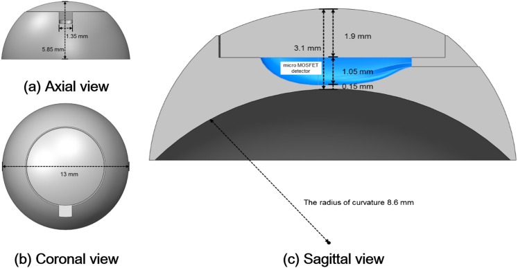
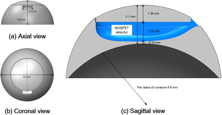
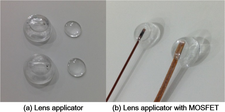
The lens applicator was designed in the shape of a contact lens. Cross-sectional diagrams of the lens applicator for the insertion of the micro MOSFET dosemeter (TN-502RDM and TN-1002RDM) and the standard MOSFET dosemeter (TN-502RD and TN-1002RD) are shown in Figures 1 and 2, respectively. The manufactured lens applicator is shown in Figure 3. It was made of acrylic with diameter and height of 13.0 and 5.85 mm, respectively. The inner radius of curvature was 8.6 mm. It consisted of two parts, one was the base of the applicator with a hole for the insertion of a MOSFET dosemeter and the other was a cover. The thicknesses of the covers were 1.9 mm for the micro MOSFET dosemeter and 1.36 mm for the standard MOSFET dosemeter. The distance from the MOSFET dosemeter to the ocular surface was 0.15 mm.
Figure 1.
The axial (a), coronal (b) and sagittal (c) views of the lens applicator for in vivo dosimetry of lens dose using micro metal oxide semiconductor field effect transistor (MOSFET) dosemeter are shown. The diameter and the height were 13.00 and 5.85 mm, respectively. The thickness from the dosemeter to the ocular surface was 0.15 mm. The applicator was made of acrylic and consisted two parts that were a cover and a base.
Figure 2.
The axial (a), coronal (b) and sagittal (c) views of the lens applicator for in vivo dosimetry of lens dose using standard metal oxide semiconductor field effect transistor (MOSFET) dosemeter are shown. The diameter and the height were 13.00 and 5.85 mm, respectively. The thickness from the dosemeter to the ocular surface was 0.15 mm. The applicator was made of acrylic and consisted two parts that were a cover and a base.
Figure 3.
Two-types of lens applicators for lens in in vivo dosimetry are shown (a). One was for the insertion of micro metal oxide semiconductor field effect transistor (MOSFET) dosemeter (top) and the other was for the insertion of standard MOSFET dosemeter (bottom). Micro and standard MOSFET dosemeter inserted into the lens applicators are shown (b).
Calibration and characterization of metal oxide semiconductor field effect transistor dosemeter
The bias sensitivity setting of the reader was set to high since the range of dose in this study was <100 cGy. For the measurements from 1 to 20 cGy, a high sensitivity MOSFET dosemeter (TN-1002RDM and TN-1002RD) was used, whereas for measurements from 20 to 100 cGy, a standard sensitivity MOSFET dosemeter (TN-502RDM and TN-502RD) was used following manufacturer recommendations. The dosemeters were calibrated by delivering 1 Gy with a 6-MV photon beam. Before the dosemeter calibration, the 6-MV photon beam was calibrated according to the American Association of Physicists in Medicine (AAPM) Task Group (TG) 51 protocol to deliver 1 Gy at the depth of dose maximum.22 After that, calibration of the dosemeters was performed in a solid water phantom at the depth of dose maximum. By doing so, a value of millivolts per centigray for each MOSFET dosemeter was acquired. The reliability of the MOSFET dosemeters used in this study was investigated to see if they were compatible for dose measurements of VMAT plans or not. The dose linearity of each MOSFET dosemeter was verified in the range of 5–100 cGy. Since the shape of the MOSFET dosemeter is not spherical, angular dependency was checked at gantry angles from 0° to 180° at intervals of 45°. The dose rate dependency was also investigated from 100 to 600 MU min−1 at intervals of 100 MU min−1. The depth dose dependency was checked with comparison to the measured values with a parallel-plate chamber in a solid water phantom. We acquired a value of monitor units (MUs), which delivers 100 cGy at the depth of dose maximum. After MU delivery, measurements with a parallel-plate chamber, as well as the MOSFET dosemeters, were performed at various depths, including surface, in a solid water phantom. The readings were then normalized to the maximum dose, thereby, we acquired percent depth doses (PDDs). We then compared PDDs of the parallel-plate chamber and MOSFET dosemeters at each depth.
Anthropomorphic phantom with the lens applicator
An anthropomorphic phantom (Model 702 Phantom; CIRS, Norfolk, VA) equipped with a micro MOSFET dosemeter inserted into the lens applicator underwent CT scans (MIC CT) with Brilliance CT Big BoreTM (Philips Healthcare, Amsterdam, Netherlands). CT images of the phantom with a standard MOSFET dosemeter inserted into the lens applicator (STD CT) were also acquired. In addition, for the simulation of conventional in vivo measurement of lens dose at the surface of the eyelid, CT images of the anthropomorphic phantom without the lens applicator (original CT) were also acquired. Therefore, a total of three sets of CT images were acquired. The slice thickness of CT images was 1.5 mm. For the full attachment of the lens applicator to the anthropomorphic phantom, wax was used to fill the space between the curved inner surface of the applicator and the rigid flat surface of the phantom.
Treatment planning and delivery of 10 brain and 10 head and neck volumetric modulated arc therapy plans
After an institutional review board approval, a total of 20 patients who underwent VMAT for brain tumour (10 patients) and for H&N cancer (10 patients) were chosen retrospectively for this study. Each of the structures in the VMAT plans including targets and OARs were contoured on the original CT by a radiation oncologist. And then, every structure in the original CT was registered to the MIC CT and the STD CT. A total of 20 new VMAT plans for brain and H&N cancers were generated at the original CT using EclipseTM (Varian Medical Systems) with the same prescriptions used in the actual treatments of each patient. When generating new VMAT plans, the constraints for lens dose were in the range of 0.5–17.0 Gy, rather than the clinically typical 7 Gy in order to test the performance of the lens applicator across a wider range of doses. Optimizations were performed with a progressive resolution optimizer 3 (PRO 3 v. A10) algorithm and dose distributions were calculated using AAA (v. A10) with a calculation grid of 1 mm. Trilogy with Millennium™ MLC (Varian Medical Systems) was used for the planning and delivery. Two arcs with full gantry rotation and 6-MV photon beams were used for the planning. After that, the generated VMAT plans were assigned to the MIC CT and STD CT and dose distributions were calculated. The dose distributions of each set of three CT images for a single VMAT plan were identical except in the region of the lens applicator. Therefore, when we collected the calculated dose data for the lens applicator with the micro MOSFET dosemeter, we used the dose distribution calculated on the MIC CT. We used the same process for the lens applicator with the standard MOSFET dosemeter (STD CT) and the measurements at the surface of the eyelid without the lens applicator (original CT). Before the delivery of VMAT plans to the anthropomorphic phantom for the measurements of lens dose, the output of the linac was calibrated according to the AAPM TG 51 protocol.22 The set-up of the anthropomorphic phantom was performed with image guidance using cone beam CT (CBCT) to minimize the set-up errors, as set-up errors could have an influence on the results. Measurements were performed for both lenses with both micro and standard MOSFET dosemeters. We measured doses with the lens applicator as well as on the surface of the eyelid.
Data analysis by comparison between the measured vs calculated doses
Differences between the calculated eye lens doses and the measured doses at the surface were acquired to investigate the accuracy of the conventional in vivo dosimetry for the eye lens. In this case, the point of calculation was different from the point of measurement (eye lens vs surface of eyelid). After that, the calculated doses at the surface of the eyelid were compared with the measured values at the surface of the eyelid without the lens applicator (the same point for both the calculation and the measurement). Since we acquired CT images with the MOSFET dosemeters inserted, it was possible to identify the detecting element in the CT images. The point of calculation was determined as the centre of the identified volume of the detecting element with a voxel size of 1 mm3 since the calculation grid was 1 mm. Finally, the calculated doses at the MOSFET dosemeter inside the lens applicator, and the measured values inside the lens applicator were compared (the same point for both the calculation and the measurement). The averaged values of the differences were acquired using absolute values of differences between the calculation and the measurement for each patient to prevent the cancelling out of positive values with the negative values. The differences were averaged from a total of 40 cases (20 patients × 2 lenses for 1 patient). The differences were acquired as absolute values (cGy) as well as relative values (%). The percent difference was acquired as follows:
| (1) |
The two-sided Student's t-test with 95% confidence intervals was performed to investigate the statistical significances of differences between the results with and without the lens applicator. The maximum difference between the calculation and measurement was also acquired. The number of cases over 20%, 30%, 40% and 50% difference among a total of 40 cases were acquired with and without the lens applicator.
RESULTS
Metal oxide semiconductor field effect transistors dosemeter characterization
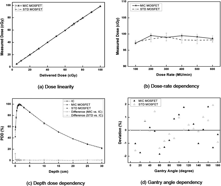
The characteristics of both the micro and the standard MOSFET dosemeters are shown in Figure 4. From the delivery of 5–100 cGy, the average difference between the delivered dose and the reading of the micro MOSFET dosemeter was 0.6%, with a maximum difference of 2.2% at 5 cGy. The average difference with the standard MOSFET dosemeter was 0.1% with a maximum difference of 3.2% at 10 cGy. The micro and standard MOSFET dosemeters showed a linear response with linearity coefficient of 0.9897 and 0.9817 for a dose range of 5–100 cGy, respectively, indicating good dose linearity. The averaged value of the standard deviation (SD) from 100 to 600 MU min−1 was 0.67 cGy for the micro MOSFET dosemeter and 0.80 cGy for the standard MOSFET dosemeter when delivering 98 cGy, showing minimal dose rate dependency. In the case of depth dose measurements, excluding the measurement at the surface, the averaged differences were 0.7% for the micro MOSFET dosemeter and 0.8% for the standard MOSFET dosemeter from a depth of 0.1–30.0 cm. At the surface, the difference was 12.3% with the micro MOSFET dosemeter and 11.6% with the standard MOSFET dosemeter. The differences in MOSFET dosemeter readings at various gantry angles from the reading at the gantry angle of 0° were <2% for both micro and standard MOSFET dosemeters. No noticeable difference between the micro and standard MOSFET dosemeters was observed.
Figure 4.
The dose linearity (a), dose rate dependency (b), depth dose dependency (c) and angular dependency (d) of both micro (MIC) and standard (STD) metal oxide semiconductor field effect transistors (MOSFET) dosemeter are shown. The percent depth doses (PDDs) acquired with MOSFET dosemeter were compared with the PDDs acquired with parallel-plate chamber. The measured values with MOSFET dosemeter at various gantry angles were compared with the measured value at the gantry angle of 0°. IC, ion chamber; MU, monitor unit.
Results of in vivo dosimetry for eye lens
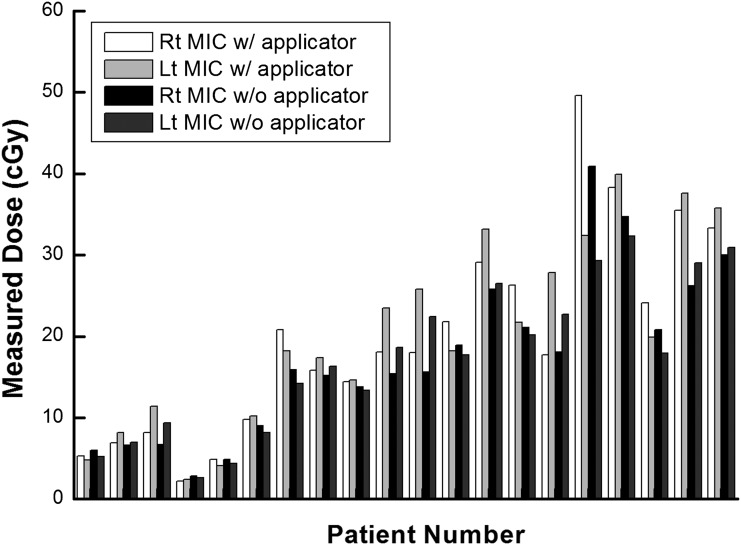
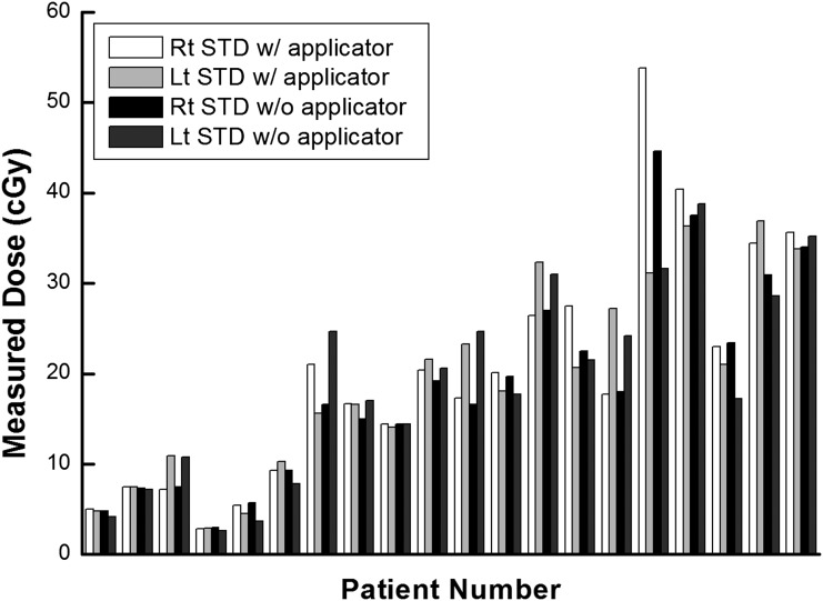
The measured doses at the lens and the surface of the eyelid by the micro and standard MOSFET applicators are shown in Figures 5 and 6, respectively. The average values of measured dose on the surface of the eyelid with micro and standard MOSFETs were 17.4 and 18.8 cGy, respectively, the average difference in dose being 1.4 cGy. Those values measured with the lens applicator were 20.2 and 19.9 cGy, showing an average dose difference of 0.3 cGy. The maximum difference between the measured doses with and without the applicator was 9.3 cGy using the micro MOSFET and 9.2 cGy with the standard MOSFET.
Figure 5.
The measured values using micro metal oxide semiconductor field effect transistor (MOSFET) dosemeter at the surface of eyelid and at the lens applicator are shown in units of centigray. Lt, left; MIC, micro; Rt, right; w/, with; w/o, without.
Figure 6.
The measured values using metal oxide semiconductor field effect transistors dosemeter at the surface of eyelid and at the lens applicator are shown in units of centigray. Lt, left; Rt, right; STD, standard; w/, with; w/o, without.
Measured vs calculated dose with and without the lens applicator
The doses to the lens calculated by the TPS with and without the lens applicator are shown in Table 1 for 20 VMAT plans. Based on the calculation, the average increase of dose to the lens for VMAT was 46.1% with the micro MOSFET applicator and 33.0% with the standard MOSFET applicator. The average dose difference to the lens between the micro and standard MOSFET applicators was 7.7%.
Table 1.
The prescription doses and the calculated doses per single fraction for each volumetric modulated arc therapy plan
| Site | Patient number | Prescription dose (Gy)/fraction number | Calculated dose for right lens per fraction with TPS (cGy) |
Calculated dose for left lens per fraction with TPS (cGy) |
||||
|---|---|---|---|---|---|---|---|---|
| NA | MIC | STD | NA | MIC | STD | |||
| Brain | 1 | 36/12 | 8.9 | 8.3 | 8.4 | 7.1 | 8.5 | 8.2 |
| Brain | 2 | 45/25 | 10.0 | 12.4 | 11.8 | 9.1 | 18.0 | 16.3 |
| H&N | 3 | 50.5/25 | 10.9 | 16.3 | 15.8 | 13.3 | 17.0 | 16.8 |
| Brain | 4 | 45/15 | 4.0 | 4.1 | 3.9 | 3.2 | 4.4 | 3.8 |
| Brain | 5 | 45/10 | 11.5 | 21.5 | 20.2 | 6.1 | 14.5 | 11.7 |
| Brain | 6 | 67.5/30 | 15.5 | 23.6 | 20.8 | 13.0 | 22.3 | 21.1 |
| H&N | 7 | 63/28 | 25.5 | 39.4 | 36.6 | 21.6 | 28.2 | 26.6 |
| H&N | 8 | 36/12 | 22.9 | 27.5 | 27.8 | 21.2 | 22.9 | 22.7 |
| Brain | 9 | 50.4/28 | 23.8 | 30.9 | 27.0 | 19.9 | 29.9 | 27.1 |
| Brain | 10 | 72/30 | 24.2 | 30.6 | 29.2 | 22.1 | 28.5 | 27.6 |
| Brain | 11 | 67.5/30 | 24.4 | 30.3 | 28.1 | 29.9 | 38.6 | 38.2 |
| Brain | 12 | 60.75/27 | 25.8 | 29.3 | 28.7 | 24.8 | 29.5 | 29.3 |
| H&N | 13 | 67.5/30 | 39.2 | 94.9 | 79.3 | 33.4 | 35.8 | 33.7 |
| H&N | 14 | 30/12 | 31.9 | 43.0 | 40.8 | 30.3 | 44.2 | 38.7 |
| H&N | 15 | 45/25 | 26.2 | 56.9 | 39.5 | 28.7 | 35.6 | 34.2 |
| H&N | 16 | 67.5/30 | 55.5 | 131.8 | 108.0 | 28.3 | 33.3 | 32.5 |
| H&N | 17 | 33/10 | 58.8 | 87.2 | 71.3 | 35.5 | 55.8 | 46.3 |
| Brain | 18 | 63/28 | 36.7 | 58.9 | 49.2 | 32.7 | 51.6 | 48.7 |
| H&N | 19 | 63/28 | 44.8 | 64.1 | 60.2 | 43.2 | 61.1 | 60.7 |
| H&N | 20 | 67.5/30 | 36.3 | 44.6 | 45.7 | 42.2 | 64.7 | 53.1 |
H&N, head and neck cancer; MIC, lens dose with applicator for micro metal oxide semiconductor field effect transistor dosemeter; NA, lens dose without applicator; STD, lens dose with applicator for standard metal oxide semiconductor field effect transistor dosemeter; TPS, treatment planning system.
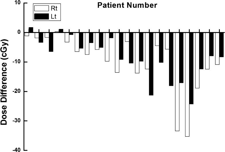
The difference between the measured dose at the surface of the eyelid and the calculated dose to the lens for each patient is shown in Figure 7. The averaged difference was 9.5 ± 8.2 cGy and the maximum difference was 35.3 cGy. Since the surface doses were lower than the doses to the lens, most of the differences had negative values. Because the location of the lens was different from the location of the measurement point at the surface of the eyelid, there were noticeable differences between the measured and the calculated doses during conventional in vivo dosimetry.
Figure 7.
The differences between the measured values with standard metal oxide semiconductor field effect transistor dosemeter at the surface of the eyelid and the calculated dose to the lens with treatment planning system for each patient are shown in units of centigray. Lt, left; Rt, right.
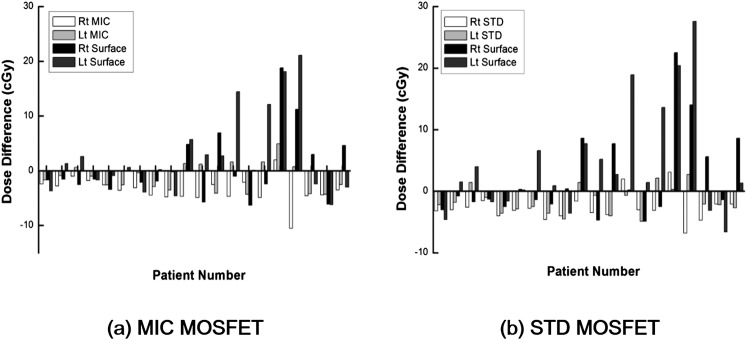
The differences between the measured and the calculated doses for each patient with and without the lens applicator are illustrated in Figure 8. The averaged differences and the maximum differences are shown in Table 2. In the case of the micro MOSFET dosemeter, the averaged difference between the measured dose inside the lens applicator and the calculated dose with TPS at the same point was 3.1 ± 1.8 cGy, whereas the averaged difference between the measured and calculated doses at the surface without the lens applicator was 4.8 ± 5.2 cGy (p = 0.024). The maximum difference with and without the lens applicator was 10.5 and 21.1 cGy, respectively. The averaged percent difference with and without the applicator was 16.8 ± 10.4% and 35.9 ± 41.5%, respectively (p = 0.003). The maximum percent difference was 46.0% with the lens applicator and 188.4% without the lens applicator. The number of cases over 20%, 30%, 40% and 50% difference with the lens applicator were 15, 5, 1 and 0 among a total of 40 cases, whereas those numbers were 21, 14, 11 and 6 without the lens applicator.
Figure 8.
The differences between the measured dose with micro metal oxide semiconductor field effect transistor (MOSFET) dosemeter [micro (MIC)] (a) inserted into the lens applicator and the calculated dose at the lens applicator with treatment planning system as well as the differences between the measured dose at the surface of eyelid and the calculated dose at the same location are shown in units of centigray for each patient. The same data with standard MOSFET dosemeter are also shown (b). Lt, left; Rt, right; STD, standard.
Table 2.
The difference between the calculated and measured doses to eye lens and the number of cases over a certain percent difference during volumetric modulated arc therapy
| Analysis | Lens applicator |
Surface |
p-value |
Lens applicator |
Surface |
p-value |
|---|---|---|---|---|---|---|
| MIC MOSFET | STD MOSFET | |||||
| Average difference (cGy) | 3.1 ± 1.8 | 4.8 ± 5.2 | 0.024 | 2.8 ± 1.3 | 5.7 ± 6.5 | 0.004 |
| Maximum difference (cGy) | 10.5 | 21.1 | 6.8 | 27.6 | ||
| Average percent difference (%) | 16.8 ± 10.4 | 35.9 ± 41.5 | 0.003 | 16.6 ± 10.9 | 42.9 ± 52.2 | 0.002 |
| Maximum percent difference (%) | 46 | 188.4 | 44.4 | 246.4 | ||
| Number of cases over 20% difference | 15 | 21 | 13 | 22 | ||
| Number of cases over 30% difference | 5 | 14 | 5 | 18 | ||
| Number of cases over 40% difference | 1 | 11 | 2 | 11 | ||
| Number of cases over 50% difference | 0 | 6 | 0 | 11 | ||
Lens applicator, inside the lens applicator; MIC MOSFET, micro metal oxide semiconductor field effect transistor dosemeter; STD MOSFET, standard MOSFET dosemeter; surface, at the surface of the eyelid.
The effective point of measurement and calculation was at the centre of the detecting element of the MOSFET dosemeter.
The results of the standard MOSFET dosemeter were similar to those of the micro MOSFET dosemeter. The averaged difference between the measured and calculated doses with the applicator was 2.8 ± 1.3 cGy, whereas that without the applicator was 5.7 ± 6.5 cGy (p = 0.004). The maximum difference with and without the applicator was 6.8 and 27.6 cGy. The averaged percent difference with and without the applicator was 16.6 ± 10.9% and 42.9 ± 52.2%, respectively (p = 0.002). The maximum percent difference with the applicator was 44.4% and 246.4% without. The number of cases over 20%, 30%, 40% and 50% difference with the lens applicator were 13, 5, 2 and 0 among a total of 40 cases, and without the applicator, those numbers were 22, 18, 11 and 11.
DISCUSSION
In this study, an applicator in the form of a contact lens was developed to improve accuracy of in vivo measurements of the dose to the eye lens over conventional in vivo measurement during radiotherapy. Micro and standard MOSFET dosemeters can to be inserted into the lens applicator, enabling real-time dosimetry during treatment. The differences between the measured and the calculated doses with the lens applicator were compared with those without the lens applicator. The statistical significances of the differences between the results with and without the applicator were analysed.
The performance of the MOSFET dosemeters was tested before measurement of the eye lens dose. Since we measured the lens dose during VMAT, the dose linearity, dose rate dependency, depth dose dependency and angular dependency were investigated. MOSFET dosemeters used in this study showed reliable performance in accordance with the results of previous studies.18–21 Since previous studies have demonstrated that the energy dependency of MOSFET dosemeters is negligible in the energy range of this study, it was not evaluated.23–26
As shown in the results, the measured dose on the surface of the eyelid does not accurately represent the delivered dose to the lens. The difference between the measured dose at the surface and the calculated lens dose could be up to 35 cGy for a single fraction delivery. This was reasonable as the eye lens was contoured to sit about 3 mm below the surface, making the measurement point different from the calculation point. In real clinical situations, this discrepancy of location increases by thickness of the eyelid if the patient closes his eyes.13 The measured doses were always lower than the calculated lens doses except in three cases among a total of 40 since the lens doses were larger than those at the surface in every VMAT plan. For the three cases, the magnitude of the differences was <2 cGy and seems to be owing to the uncertainty in measurements. Therefore, it is not appropriate to evaluate the delivered dose to the lens with in vivo dosimetry on the eyelid of patients. Instead, the measured dose at the surface should be compared with the calculated dose at the surface, and the dose to the lens would be evaluated with these results indirectly. The differences between the measured and the calculated doses at the same location, that is, at the surface, were less than those between the measured doses at the surface and the calculated eye lens doses.
The averaged difference with the lens applicator was smaller than the averaged difference without the lens applicator, even though the magnitudes of the differences were not large (3.1 vs 4.8 cGy with the micro MOSFET dosemeter and 2.8 vs 5.7 cGy with the MOSFET dosemeter). However, the values of SD were smaller for the measurements with the lens applicator than without it (1.8 vs 5.2 cGy with the micro MOSFET dosemeter and 1.3 vs 6.5 cGy with the standard MOSFET dosemeter). In addition, the maximum difference with the lens applicator was much smaller than the maximum difference without the lens applicator (10.5 vs 21.1 cGy with the micro MOSFET dosemeter and 6.8 vs 27.6 cGy with the standard MOSFET dosemeter). Among a total of 40 cases, the number of differences >50% between the measured and calculated doses with the lens applicator was 0 when using both the micro and standard MOSFET dosemeters, whereas without the lens applicator, there were 6 >50% with the micro MOSFET dosemeter and 11 with the standard MOSFET dosemeter. Therefore, in vivo dosimetry with the lens applicator seems more robust than without. This is owing to the considerable uncertainty in dosimetry on the surface due to the high dose gradient as well as the low accuracy in the surface region of the calculations by commercial TPS.14,15 Therefore, even with the lens applicator, the deviation between the measured and the calculated doses was not eliminated completely since the MOSFET dosemeters were located inside the lens applicator at depths of 1.9 mm for the micro MOSFET dosemeter and 1.4 mm for the standard MOSFET dosemeter. While not eliminating deviation entirely, the lens applicator was able to reduce the deviation for in vivo dosimetry of the eye lens. In addition, the eye lens would be located at a depth >6 mm by adopting the lens applicator since the thickness of the applicator was about 3 mm.13 Akino et al14 has demonstrated that the accuracy of dose calculation by TPS is reliable at depths >6 mm, thus the calculated dose to the lens would be more reliable with the lens applicator. Even though the dose to the lens increased, as shown in the results, if we are able to assess the lens dose accurately with the applicator, then it would be possible to reduce the lens dose during VMAT optimization with dose constraints.
The limitation of this study was that we did not apply the thermoplastic mask that is usually used during radiotherapy for brain tumour and H&N cancer. The thickness of the thermoplastic mask varies according to the manufacturer and is generally up to 3 mm. When applying the thermoplastic mask, the results of in vivo measurements at the surface of the eyelid could be more accurate than the presented results owing to the build-up effect of the mask. However, we predict that it would be difficult to guarantee the full attachment of the mask to the skin of the eyelid to give appropriate build-up for in vivo measurement at every fraction. On the other hand, the applicator suggested in this study could guarantee full attachment since it was designed in the shape of a contact lens. In addition, in vivo measurement with the lens applicator may be more accurate than the presented results in this study if the thermoplastic mask is applied. The effects of the thermoplastic mask will be investigated as a future work. The other limitation of this study was that we did not evaluate the set-up uncertainty by performing repeat measurements, which could have an effect on the results. The same MOSFET dosemeters used in the calibration and characterization procedure were used for the measurements to eliminate disturbance factors caused by using different dosemeters. However, MOSFET dosemeters have limited lifetimes before expiration, so we were unable to measure the lens dose more than one time for each VMAT plan. We decided that elimination of the disturbance factor was more important than the set-up errors. To reduce set-up errors, we set up the phantom with CBCT before delivery of VMAT plans. Since the phantom is rigid and does not move, we believe that the set-up with CBCT could make the set-up errors minimal.
Since the lens applicator was made of acrylic and contact lens-shaped, putting on the applicator was harmless and easy. In addition, since it was possible to read the delivered dose in real time with the MOSFET dosemeter, immediate evaluation was possible with the presented in vivo dosimetry system. Even though it was not possible to eliminate the deviation completely between the measured and the calculated doses, even with the lens applicator, we observed reduced deviations by applying the lens applicator when compared with conventional in vivo measurement.
CONCLUSION
An applicator for the in vivo measurement of eye lens dose has been developed, and the performance was evaluated. More robust in vivo dosimetry can be performed with the suggested applicator than with conventional in vivo dosimetry. The developed applicator was harmless to the patient and easy to put on.
FUNDING
This work was supported by grant no. 04-2013-1050 from the Seoul National University Hospital Research Fund.
REFERENCES
- 1.Henk JM, Whitelocke RA, Warrington AP, Bessell EM. Radiation dose to the lens and cataract formation. Int J Radiat Oncol Biol Phys 1993; 25: 815–20. [DOI] [PubMed] [Google Scholar]
- 2.Pawlicki T, Luxton G, Le QT, Findley D, Ma CM. Lens dose in MLC-based IMRT treatments of the head and neck. Int J Radiat Oncol Biol Phys 2004; 59: 293–9. doi: 10.1016/j.ijrobp.2004.01.019 [DOI] [PubMed] [Google Scholar]
- 3.Woo SY, Donaldson SS, Heck RJ, Nielson KL, Shostak C. Minimizing and measuring lens dose when giving cranial irradiation. Radiother Oncol 1989; 16: 183–8. [DOI] [PubMed] [Google Scholar]
- 4.Ma L, Chin L, Sarfaraz M, Shepard D, Yu C. An investigation of eye lens dose for gamma knife treatments of trigeminal neuralgia. J Appl Clin Med Phys 2000; 1: 116–19. doi: 10.1120/1.1308191 [DOI] [PMC free article] [PubMed] [Google Scholar]
- 5.Behrens R, Dietze G. Dose conversion coefficients for photon exposure of the human eye lens. Phys Med Biol 2011; 56: 415–37. doi: 10.1088/0031-9155/56/2/009 [DOI] [PubMed] [Google Scholar]
- 6.Edwards CR, Grieveson MH, Mountford PJ, Rolfe P. A survey of current in vivo radiotherapy dosimetry practice. Br J Radiol 1997; 70: 299–302. doi: 10.1259/bjr.70.831.9166056 [DOI] [PubMed] [Google Scholar]
- 7.Ramsell TG, Berry RJ. Recovery from x-ray damage to the lens. The effects of fractionated x-ray doses observed in rabbit lens epithelium irradiated in vivo. Br J Radiol 1966; 39: 853–8. [DOI] [PubMed] [Google Scholar]
- 8.RTOG 0539 protocol. Phase II trial of observation for low-risk meningiomas and of radiotherapy for intermediate- and high-risk meningiomas. Available from: http://www.rtog.org/ClinicalTrials/ProtocolTable/StudyDetails.aspx?study=0539
- 9.Emami B, Lyman J, Brown A, Coia L, Goitein M, Munzenrider JE, et al. Tolerance of normal tissue to therapeutic irradiation. Int J Radiat Oncol Biol Phys 1991; 21: 109–22. [DOI] [PubMed] [Google Scholar]
- 10.Oh SA, Kang MK, Kim SK, Yea JW. Comparison of IMRT and VMAT techniques in spine stereotactic radiosurgery with International Spine Radiosurgery Consortium consensus guidelines. Prog Med Phys 2013; 24: 145–53. [Google Scholar]
- 11.Lee SH, Lee KC, Choi J, Kim HY, Lee SH, Sung KH, et al. Clinical application of RapidArc volumetric modulated arc therapy as a component in whole brain radiation therapy for poor prognostic, four or more multiple brain metastases. Radiat Oncol J 2012; 30: 53–61. doi: 10.3857/roj.2012.30.2.53 [DOI] [PMC free article] [PubMed] [Google Scholar]
- 12.Teoh M, Clark CH, Wood K, Whitaker S, Nisbet A. Volumetric modulated arc therapy: a review of current literature and clinical use in practice. Br J Radiol 2011; 84: 967–96. doi: 10.1259/bjr/22373346 [DOI] [PMC free article] [PubMed] [Google Scholar]
- 13.Charles MW, Brown N. Dimensions of the human eye relevant to radiation protection. Phys Med Biol 1975; 20: 202–18. [DOI] [PubMed] [Google Scholar]
- 14.Akino Y, Das IJ, Bartlett GK, Zhang H, Thompson E, Zook JE. Evaluation of superficial dosimetry between treatment planning system and measurement for several breast cancer treatment techniques. Med Phys 2013; 40: 011714. doi: 10.1118/1.4770285 [DOI] [PubMed] [Google Scholar]
- 15.Court LE, Tishler R, Xiang H, Allen AM, Makrigiorgos M, Chin L. Experimental evaluation of the accuracy of skin dose calculation for a commercial treatment planning system. J Appl Clin Med Phys 2008; 9: 2792. [DOI] [PMC free article] [PubMed] [Google Scholar]
- 16.Kron T, Butson M, Hunt F, Denham J. TLD extrapolation for skin dose determination in vivo. Radiother Oncol 1996; 41: 119–23. [DOI] [PubMed] [Google Scholar]
- 17.Wilkins D, Li XA, Cygler J, Gerig L. The effect of dose rate dependence of p-type silicon detectors on linac relative dosimetry. Med Phys 1997; 24: 879–81. [DOI] [PubMed] [Google Scholar]
- 18.Ciocca M, Piazzi V, Lazzari R, Vavassori A, Luini A, Veronesi P, et al. Real-time in vivo dosimetry using micro-MOSFET detectors during intraoperative electron beam radiation therapy in early-stage breast cancer. Radiother Oncol 2006; 78: 213–16. [DOI] [PubMed] [Google Scholar]
- 19.Qi ZY, Deng XW, Huang SM, Shiu A, Lerch M, Metcalfe P, et al. Real-time in vivo dosimetry with MOSFET detectors in serial tomotherapy for head and neck cancer patients. Int J Radiat Oncol Biol Phys 2011; 80: 1581–8. doi: 10.1016/j.ijrobp.2010.10.063 [DOI] [PubMed] [Google Scholar]
- 20.Deshpande S, Kumar R, Ghadi Y, Neharu RM, Kannan V. Dosimetry investigation of MOSFET for clinical IMRT dose verification. Technol Cancer Res Treat 2013; 12: 193–8. doi: 10.7785/tcrt.2012.500318 [DOI] [PubMed] [Google Scholar]
- 21.Chuang CF, Verhey LJ, Xia P. Investigation of the use of MOSFET for clinical IMRT dosimetric verification. Med Phys 2002; 29: 1109–15. [DOI] [PubMed] [Google Scholar]
- 22.Almond PR, Biggs PJ, Coursey BM, Hanson WF, Huq MS, Nath R, et al. AAPM's TG-51 protocol for clinical reference dosimetry of high-energy photon and electron beams. Med Phys 1999; 26: 1847–70. [DOI] [PubMed] [Google Scholar]
- 23.Panettieri V, Duch MA, Jornet N, Ginjaume M, Carrasco P, Badal A, et al. Monte Carlo simulation of MOSFET detectors for high-energy photon beams using the PENELOPE code. Phys Med Biol 2007; 52: 303–16. doi: 10.1088/0031-9155/52/1/020 [DOI] [PubMed] [Google Scholar]
- 24.Lavallée MC, Gingras L, Beaulieu L. Energy and integrated dose dependence of MOSFET dosimeter sensitivity for irradiation energies between 30 kV and Co 60. Med Phys 2006; 33: 3683–9. [DOI] [PubMed] [Google Scholar]
- 25.Ehringfeld C, Schmid S, Poljanc K, Kirisits C, Aiginger H, Georg D. Application of commercial MOSFET detectors for in vivo dosimetry in the therapeutic x-ray range from 80 kV to 250 kV. Phys Med Biol 2005; 50: 289–303. [DOI] [PubMed] [Google Scholar]
- 26.Cheung T, Butson MJ, Yu PK. Energy dependence corrections to MOSFET dosimetric sensitivity. Australas Phys Eng Sci Med 2009; 32: 16–20. [DOI] [PubMed] [Google Scholar]


